Die
Erfindung betrifft einen Koaxialverbinder für ein Hochfrequenzkabel, nachstehend
als HF-Kabel bezeichnet.The
The invention relates to a coaxial connector for a radio frequency cable, hereinafter
referred to as RF cable.
7 zeigt einen herkömmlichen
Koaxialverbinder für
HF-Kabel 101, der mit einem Mittelstift 104 versehen
ist, der elektrisch mit einem Mittelleiter 103 eines Koaxialkabels 102 verbunden
ist. Der Mittelstift 104 ist in dem Zentrum eines Formkörper-Isolators
bzw. einer Isolierbuchse 105 gelagert. Ein Außenanschluß 106 steht
mit dem Umfang der Isolierbuchse 105 in Eingriff. Der Außenanschluß 106 ist elektrisch
mit einem Außenleiter 107 des
Koaxialkabels 102 über
ein Verbindungsstück 108 verbunden, wobei
er mittels eines Verankerungsteiles 110 an einem Kunststoffmantel 109 eines
Koaxialkabels 102 mechanisch abgestützt ist. 7 shows a conventional coaxial connector for RF cables 101 with a center pin 104 is provided, which is electrically with a center conductor 103 a coaxial cable 102 connected is. The center pin 104 is in the center of a molded body insulator or an insulating bush 105 stored. An outside connection 106 stands with the circumference of the insulating bush 105 engaged. The external connection 106 is electrical with an outer conductor 107 of the coaxial cable 102 via a connector 108 connected, he using an anchoring part 110 on a plastic jacket 109 a coaxial cable 102 is mechanically supported.
Der
Außenanschluß 106 ist
mit einem Längsschlitz 111 etwa
bis zur Mitte des Anschlusses versehen, um eine Federvorspannung
zu erzielen. Eine Isolierformbuchse 112 ist an dem Umfang
des Außenanschlusses 106 vorgesehen.The external connection 106 is with a longitudinal slot 111 about to the middle of the connection to achieve a spring preload. An insulating molded socket 112 is on the circumference of the external connection 106 intended.
Bei
einem solchen koaxialen Verbinder für HF-Kabel ist jedoch ein exakter
Außendurchmesser eines
Formkörper-Isolators
bzw. einer Isolierbuchse 105 erforderlich, und zwar wegen
des Eingriffs der Isolierbuchse 105 mit dem Zylinder des
Außenanschlusses 106.
Bisher war der Eingriff zwischen der Isolierbuchse 105 und
dem Außenanschluß 106 schwierig
herzustellen. Auch die Montage war kompliziert.With such a coaxial connector for RF cables, however, there is an exact outer diameter of a molded body insulator or an insulating bush 105 required because of the engagement of the insulating bush 105 with the cylinder of the external connection 106 , So far, the engagement between the insulating bush 105 and the external connection 106 difficult to manufacture. The assembly was also complicated.
Weiterhin
wird im Falle des Eingriffs mit einem Eingriffsvorsprung, der an
der Isolierbuchse 105 vorgesehen ist, der Eingriffsvorsprung
an dem Ende des Außenanschlusses 106 angebracht,
wenn die Montage durchgeführt
wird. Diese Anbringung führt aber
leicht zu Beschädigungen
des Eingriffsvorsprungs sowie einer Verformung des Außenanschlusses.Furthermore, in the case of engagement with an engagement projection, which is on the insulating bush 105 is provided, the engagement projection at the end of the outer connection 106 attached when the assembly is carried out. However, this attachment easily leads to damage to the engagement projection and a deformation of the external connection.
Aus
diesem Grunde ist auch eine andere Konstruktion vorgeschlagen worden,
bei der ein Schlitz in axialer Richtung zu dem Zylinder des Außenanschlusses 106 vorgesehen
ist, um den Innendurchmesser des Zylinders einzustellen. Bei einem Koaxialverbinder
für ein
HF-Kabel führte
dies jedoch zu einer Streuung bzw. einem Austritt von Hochfrequenzsignalen
durch diesen Schlitz. Ferner wird dieser Schlitz leicht aufgeweitet,
wenn eine Verbindung mit einem anderen Verbinder vorgenommen wird,
so daß der
Eingriff mit der Isolierbuchse gelöst wird. Dabei kann es zu einem
Abrutschen der Isolierbuchse von dem Zylinder kommen.For this reason, another construction has also been proposed in which a slot is in the axial direction of the cylinder of the outer connection 106 is provided to adjust the inner diameter of the cylinder. In the case of a coaxial connector for an HF cable, however, this led to the scattering or leakage of high-frequency signals through this slot. Furthermore, this slot is easily widened when a connection is made to another connector, so that the engagement with the insulating bush is released. This can cause the insulating sleeve to slip off the cylinder.
Aus
der JP-A-3-216 977 ist
ein Koaxialverbinder für
ein HF-Kabel bekannt, der einen Mittelstift aufweist, der mit einem
Mittelleiter eines Koaxialkabels verbunden ist. Eine Isolierbuchse
ist auf den Mittelstift aufgesteckt und haltert diesen Mittelstift.
Eine Massemetallhalterung steht mit der Isolierbuchse in Eingriff
und haltert diese, wobei die Massemetallhalterung einen Schlitz
und eine Öffnung
aufweist. Die Massemetallhalterung besitzt ein zylinderförmiges Teil
an ihrer Rückseite,
das mit einem Außenleiter des
Koaxialkabels verbunden ist.From the JP-A-3-216 977 a coaxial connector for an RF cable is known which has a central pin which is connected to a central conductor of a coaxial cable. An insulating bush is attached to the center pin and holds this center pin. A ground metal holder engages and holds the insulating bush, the ground metal holder having a slot and an opening. The ground metal holder has a cylindrical part on its back, which is connected to an outer conductor of the coaxial cable.
Aus
der DE 689 16 586
T2 ist ein Steckverbinder für ein mehradriges Kabel bekannt,
wobei die Adern mit eingebauten Kontaktstiften in einem Kunstharzkörper verbunden
sind. Eine zylindrische Abdeckung bildet eine Massehalterung, die
mit Abschirmdrähten
des Kabels verbunden ist und die die Isolierbuchse aufnimmt. Die
Isolierbuchse ist mit einer speziellen äußeren Konfigurierung versehen,
welche komplementäre
Entsprechungen in der Massemetallhalterung besitzt, um diese exakt
zu positionieren. Ferner ist die Massemetallhalterung mit einer
Zunge mit einem Verriegelungsvorsprung ausgerüstet, um für die örtliche Festlegung in einer äußeren Isolierungsumhüllung zu
sorgen. Weiterhin ist ein zusätzliches
zylinderförmiges
Abschirmteil vorgesehen, das den hinteren, zum Kabel verlaufenden
Teil der Massemetallhalterung überdeckt.From the DE 689 16 586 T2 a connector for a multi-core cable is known, the wires being connected with built-in contact pins in a synthetic resin body. A cylindrical cover forms a ground bracket, which is connected to the shielding wires of the cable and which receives the insulating bush. The insulating bushing is provided with a special outer configuration, which has complementary counterparts in the bulk metal holder in order to position it exactly. Furthermore, the bulk metal holder is equipped with a tongue with a locking projection in order to ensure that it is fixed in place in an outer insulation sheath. Furthermore, an additional cylindrical shielding part is provided which covers the rear part of the bulk metal holder which runs to the cable.
Der
Erfindung liegt die Aufgabe zugrunde, einen koaxialen Verbinder
für ein
HF-Kabel anzugeben, der sich bequem und zuverlässig montieren läßt und zugleich
den Austritt von Hochfrequenzsignalen verhindert, wobei zugleich
die Isolierbuchse gegen ein Abrutschen von einem Außenanschluß geschützt ist.The
The invention is based on the object of a coaxial connector
for a
Specify RF cable that can be conveniently and reliably installed and at the same time
prevents the emergence of high-frequency signals, while at the same time
the insulating bush is protected against slipping off an external connection.
Die
erfindungsgemäße Lösung besteht
darin, einen koaxialen Verbinder für ein HF-Kabel mit den Merkmalen
des Anspruchs 1 auszubilden. Vorteilhafte Weiterbildungen des erfindungsgemäßen koaxialen
Verbinders sind in den Unteransprüchen angegeben.The
solution according to the invention
therein, a coaxial connector for an RF cable with the features
of claim 1 to train. Advantageous developments of the coaxial invention
Connectors are specified in the subclaims.
Die
Erfindung wird nachstehend anhand der Beschreibung von Ausführungsbeispielen
und unter Bezugnahme auf die beiliegenden Zeichnungen näher erläutert. Die
Zeichnungen zeigen in:The
Invention is described below based on the description of exemplary embodiments
and explained in more detail with reference to the accompanying drawings. The
Drawings show in:
1 eine Schnittansicht eines
koaxialen Verbinders für
ein HF-Kabel gemäß der Erfindung; 1 a sectional view of a coaxial connector for an RF cable according to the invention;
2 eine Seitenansicht einer
Massemetallhalterung für
den Verbinder gemäß der Erfindung; 2 a side view of a bulk metal holder for the connector according to the invention;
3 eine Schnittansicht längs der
Linie B-B in 2; 3 a sectional view taken along line BB in 2 ;
4 eine Seitenansicht eines
Abschirmzylinders; 4 a side view of a shield cylinder;
5 eine Schnittansicht längs der
Linie A-A in 4; 5 a sectional view taken along line AA in 4 ;
6 eine schematische Darstellung
zur Erläuterung
des Montagevorganges für
einen koaxialen Verbinder für
ein HF-Kabel gemäß der Erfindung;
und in 6 is a schematic representation for explaining the assembly process for a coaxial connector for an RF cable according to the invention; and in
7 eine Schnittansicht eines
herkömmlichen
koaxialen Verbinders für
ein HF-Kabel. 7 a sectional view of a conventional coaxial connector for an RF cable.
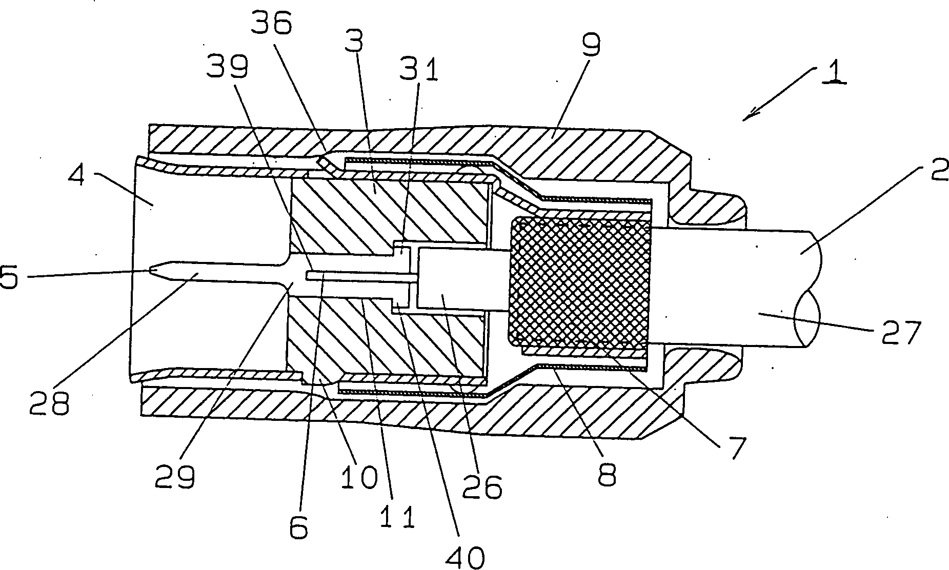
1 zeigt schematisch den
Aufbau eines koaxialen Verbinders für ein HF-Kabel gemäß der Erfindung.
Dabei bezeichnet das Bezugszeichen 1 einen koaxialen Verbinder
für ein
HF-Kabel 2.
Ferner sind eine Isolierbuchse 3, eine Massemetallhalterung 4,
ein Mittelstift 5, ein Abschirmzylinder 8 sowie
eine Formkörperabdeckung 9 vorgesehen. 1 shows schematically the structure of a coaxial connector for an RF cable according to the invention. The reference symbol denotes 1 a coaxial connector for an RF cable 2 , There is also an insulating bush 3 , a metal bracket 4 , a center pin 5 , a shield cylinder 8th as well as a molded body cover 9 intended.
Das
Koaxialkabel 2 besteht aus einem Mittelleiter 6,
einem inneren Isolator 26, einem Außenleiter 7 und einem äußeren Isolator 27. The coaxial cable 2 consists of a central conductor 6 , an inner insulator 26 , an outer conductor 7 and an outer insulator 27 ,
Der
Mittelstift 5 besteht aus einem nadelartigen Verbinder 28 und
einem zylindrischen Träger 29 sowie
einem Flansch 31. Der zylindrische Träger 29 ist an der
Rückseite
mit dem Verbinder 28 verbunden und hat einen größeren Durchmesser
als der Verbinder 28. Der Flansch 31 ist an dem
rückseitigen
Ende des zylindrischen Trägers 29 vorgesehen.
Ein Einsatzschlitz 39 eines Mittelleiters 6 ist
als Längsnut längs der
Achse von der Rückseite
des Mittelstiftes 5 aus vorgesehen.The center pin 5 consists of a needle-like connector 28 and a cylindrical support 29 as well as a flange 31 , The cylindrical support 29 is on the back with the connector 28 connected and has a larger diameter than the connector 28 , The flange 31 is at the rear end of the cylindrical support 29 intended. An insert slot 39 a center conductor 6 is a longitudinal groove along the axis from the back of the center pin 5 provided from.
Die
Isolierbuchse 3 ist zylinderförmig ausgebildet, und an dem
Umfang der Isolierbuchse 3 ist ein Eingriffsvorsprung 10 vorgesehen.
Ein Einsatzschlitz für
einen Mittelstift 11 ist als entsprechende Aussparung durch
die Isolierbuchse 3 hindurch vorgesehen. Der Einsatzschlitz
des Mittelstiftes 11 ist mit Stufen 40 versehen.The insulating bush 3 is cylindrical, and on the circumference of the insulating bush 3 is an interventional advantage 10 intended. An insert slot for a center pin 11 is a corresponding recess through the insulating bush 3 provided through. The insert slot of the center pin 11 is with steps 40 Mistake.
Wie
aus 2 und 3 ersichtlich, ist die Massemetallhalterung 4 aus
einer elastischen Metallplatte durch Preßverformung hergestellt, derart,
daß sie
zylindrisch ausgebildet ist. Die Massemetallhalterung 4 weist
ein Zylinderteil 17, das im Schnitt C-förmig ausgebildet ist, sowie
ein zylinderförmiges
Teil 15 auf, das im Schnitt U-förmig ausgebildet ist. Das durch
Preßverformung
hergestellte zylinderförmige Teil 15 ist
mit dem Zylinderteil 17 durch einen Verbinder 14 verbunden.
Dieses Zylinderteil 17 hat einen axial verlaufenden Schlitz 12.
Ein Eingriffsteil 16 ist durch Herausschneiden eines Teiles
des Zylinderteiles 17 gebildet. An der Rückseite
des Zylinderteiles 17 stehen beispielsweise vier Vorsprünge 18 vor,
die in gleichen Abständen
verteilt längs
des Umfanges des Zylinderteiles 17 vorgesehen sind. Gegebenenfalls
können
auch mehr oder weniger solche Vorsprünge 18 vor gesehen
sein. Ein viereckiges Loch 13 ist in der Mitte des Schlitzes 12 vorgesehen.
Der Verbinder 14 verbindet das Zylinderteil 17 und
das durch Preßverformung
hergestellte zylinderförmige
Teil 15 mit derselben Achse.How out 2 and 3 can be seen, the bulk metal bracket 4 made from an elastic metal plate by press forming such that it is cylindrical. The metal bracket 4 has a cylinder part 17 , which is C-shaped in section, and a cylindrical part 15 on, which is U-shaped in section. The cylindrical part made by compression molding 15 is with the cylinder part 17 through a connector 14 connected. This cylinder part 17 has an axially extending slot 12 , An engaging part 16 is by cutting out part of the cylinder part 17 educated. At the back of the cylinder part 17 there are four tabs, for example 18 before, distributed at equal intervals along the circumference of the cylinder part 17 are provided. If necessary, more or less such projections 18 be provided. A square hole 13 is in the middle of the slot 12 intended. The connector 14 connects the cylinder part 17 and the cylindrical part made by compression molding 15 with the same axis.
Wie
aus 4 und 5 ersichtlich, besteht der
Abschirmzylinder 8 aus einem Bereich 21 mit großem Durchmesser,
einem Bereich 22 mit kleinem Durchmesser sowie einem schrägen Übergang 23.How out 4 and 5 the shielding cylinder is visible 8th from an area 21 large diameter, one area 22 with a small diameter and an oblique transition 23 ,
Aus 1 läßt sich entnehmen, daß eine Formkörperabdeckung 9 am
Umfang der Massemetallhalterung 4 vorgesehen ist. Ein Eingriffs-Schrägbereich 36 ist
an der Innenoberfläche
der Formkörperabdeckung 9 vorgesehen.
Der Eingriffs-Schrägbereich 36 ist
an dem Eingriffsteil 16 der Massemetallhalterung 4 angebracht,
um zu verhindern, daß sich
die Massemetallhalterung 4 nach vorn bewegt. Out 1 can be seen that a molded body cover 9 on the circumference of the metal bracket 4 is provided. An engagement sloping area 36 is on the inner surface of the molded article cover 9 intended. The oblique engagement area 36 is on the engagement part 16 the metal bracket 4 attached to prevent the bulk metal bracket 4 moved forward.
Die
Reihenfolge der Schritte bei der Montage eines derartigen koaxialen
Verbinders 1 wird nachstehend unter Bezugnahme auf 6 der Zeichnungen erläutert. Zunächst einmal
wird das Ende eines Koaxialkabels 2 abisoliert, so daß sowohl
der Mittelleiter 6 als auch der Außenleiter 7 freiliegen.
Anschließend
wird der Außenleiter 7 nach
hinten herumgefaltet. Das auf diese Weise vorbereitete Koaxialkabel 2 wird
durch die Formkörperabdeckung 9 sowie
den Abschirmzylinder 8 hindurch eingesetzt (Schritt 1).The order of the steps in assembling such a coaxial connector 1 is described below with reference to 6 of the drawings explained. First of all, the end of a coaxial cable 2 stripped so that both the central conductor 6 as well as the outer conductor 7 exposed. Then the outer conductor 7 folded backwards. The coaxial cable prepared in this way 2 is through the molded body cover 9 and the shield cylinder 8th inserted through (step 1).
Anschließend wird
der Mittelleiter 6 des Koaxialkabels 2 in den
Einsatzschlitz 39 des Mittelstiftes 5 eingesetzt.
Danach wird der zylindrische Träger 29 verklemmt
oder verstemmt, damit er an dem Mittelstift 5 des Mittelleiters 6 hält und haftet.
Diese Haftverbindung zwischen dem Mittelleiter 6 und dem
Mittelstift 5 braucht nicht durch Verstemmen oder Verklemmen
zu erfolgen, es ist auch möglich,
diese Bauteile miteinander zu verlöten (Schritt 2).Then the middle conductor 6 of the coaxial cable 2 in the insert slot 39 of the center pin 5 used. After that, the cylindrical support 29 jammed or caulked to the center pin 5 of the middle conductor 6 holds and is liable. This adhesive connection between the center conductor 6 and the center pin 5 does not need to be done by caulking or jamming, it is also possible to solder these components together (step 2).
Danach
wird die Isolierbuchse 3 in die Massemetallhalterung 4 gegen
ihre Federvorspannung eingesetzt, und zwar von der Vorderseite der
Massemetallhalterung 4. Dabei kommt der Eingriffsvorsprung 10 mit
einem viereckigen Loch in Eingriff, wenn der Eingriffsvorsprung 10 dieses
viereckige Loch 13 erreicht. Die Isolierbuchse 3 wird
durch den Eingriff mit der Massemetallhalterung 4 gehalten (Schritt
3).Then the insulating bush 3 into the metal bracket 4 used against their spring preload, from the front of the metal bracket 4 , The interventional advantage comes here 10 engages with a square hole when the engaging protrusion 10 this square hole 13 reached. The insulating bush 3 is by engaging the bulk metal bracket 4 held (step 3).
Danach
wird der Mittelstift 5 in ein Loch für den Mittelstift 11 der
Isolierbuchse 3 eingesetzt, und zwar von der Rückseite
der Isolierbuchse 3, bis der Flansch 31 an den
Stufen 40 angreift. Zu diesem Zeitpunkt befindet sich das
durch Preßverformung gebildete
zylinderförmige
Teil 15 auf dem nach hinten herumgefalteten Außenleiter 7 des
Koaxialkabels 2 (Schritt 4).Then the center pin 5 in a hole for the center pin 11 the insulating bush 3 inserted, from the back of the insulating sleeve 3 until the flange 31 on the steps 40 attacks. At this time, the cylindrical part formed by compression molding is located 15 on the outer conductor folded backwards 7 of the coaxial cable 2 (Step 4).
Beim
nächsten
Schritt wird das zyliderförmige
Teil 15 verstemmt bzw. mit dem herumgefalteten Außenleiter 7 in
Klemm- oder Quetscheingriff gebracht (Schritt 5).The next step is the cylindrical part 15 caulked or with the folded outer conductor 7 brought into clamping or squeezing engagement (step 5).
Anschließend wird
der Abschirmzylinder 8, der vorher beim Schritt 1 auf das
Koaxialkabel 2 aufgesetzt worden ist, abgedeckt, so daß der Bereich 21 mit
großem
Durchmesser den hinteren Bereich der Massemetallhalterung 4 verdeckt,
während
der Bereich 22 mit kleinem Durchmesser das zylinderförmige Teil 15 verdeckt.
Anschließend
wird der Bereich 22 mit kleinem Durchmesser verstemmt und
elektrisch und mechanisch mit dem zylinderförmigen Teil 15 verbunden.
Zu diesem Zeitpunkt sind die Vorsprünge 18 der Massemetallhalterung 4 an
der Innenoberfläche
des Bereiches 21 mit großem Durchmesser angebracht,
und das Zylinderteil 17 wird durch einen steifen Eingriff
elektrisch und mechanisch mit dem Abschirmzylinder 8 verbunden
(Schritt 6.Then the shield cylinder 8th which was previously on step 1 on the coaxial cable 2 has been covered, covering the area 21 with a large diameter the rear area of the metal holder 4 covered up while the area 22 with a small diameter the cylindrical part 15 covered. Then the area 22 with a small diameter, caulked electrically and mechanically with the cylindrical part 15 connected. At this point are the tabs 18 the metal bracket 4 on the inside surface of the area 21 attached with large diameter, and the cylinder part 17 becomes electrically and mechanically with the shielding cylinder by a rigid engagement 8th connected (step 6.
Daraufhin
wird die Massemetallhalterung 4 mit der Formkörperabdeckung 9 abgedeckt,
die vorher auf das Koaxialkabel 2 aufgesetzt worden ist.
Ein Wegrutschen nach hinten wird verhindert, indem man sowohl das
Eingriffsteil 16 als auch den Eingriffsvorsprung 10 an
dem stufenförmigen
Teil 36 anbringt. Andererseits wird ein Wegrutschen nach
vorn dadurch verhindert, daß man
die Innenwand der Formkörperabdeckung 9 an
dem schrägen Übergang 23 des
Abschirmzylinders 8 anbringt.Then the bulk metal bracket 4 with the molded body cover 9 covered that previously on the coaxial cable 2 has been put on. Slipping backwards is prevented by both the engaging part 16 as well as the engagement advantage 10 on the step-shaped part 36 install. On the other hand, slipping forward is prevented by having the inner wall of the molded body cover 9 at the sloping transition 23 of the shielding cylinder 8th install.
Wenn
man einen anderen Verbinder in den koaxialen Verbinder für ein HF-Kabel,
der auf diese Weise montiert worden ist, von der Vorderseite einsetzt,
so wird die Massemetallhalterung 4 durch elastische Verformung
nach außen
aufgeweitet. Zu diesem Zeitpunkt ermöglicht es der koaxiale Verbinder, daß der andere
Verbinder eingesetzt wird und sorgt dafür, daß man die vorgegebene Eingriffskraft
erzielt.If you insert another connector into the coaxial connector for an RF cable that has been assembled in this way, from the front, the bulk metal bracket becomes 4 widened outwards by elastic deformation. At this point, the coaxial connector allows the other connector to be inserted and ensures that the predetermined engagement force is achieved.
Da
ein derartiger koaxialer Verbinder gemäß der Erfindung für ein HF-Kabel
einen Schlitz 12 von dem vorderen Ende der Massemetallhalterung 4 bis zu
dem hinteren Ende aufweist, ermöglicht
dies, daß sich
die Isolierbuchse 3 leicht in die Massemetallhalterung 4 einsetzen
läßt, wobei
die Montage bequem durchgeführt
werden kann. Da weiterhin der Abschirmzylinder 8 die Massemetallhalterung 4 derart überdeckt,
daß der
hintere Bereich des Schlitzes 12 verdeckt wird, verhindert
er, daß die
Isolierbuchse 3 aus der Massemetallhalterung 4 durch
eine Aufweitung des Schlitzes 12 im Gebrauch herausrutscht. Weiterhin
ist es möglich,
einen Austritt von Hochfrequenzsignalen durch den Schlitz 12 zu
verhindern.Since such a coaxial connector according to the invention for a RF cable has a slot 12 from the front end of the bulk metal bracket 4 to the rear end, this allows the insulating bush to be 3 easily into the metal bracket 4 can be used, the assembly can be carried out comfortably. Since the shield cylinder continues 8th the metal bracket 4 so covered that the rear portion of the slot 12 is covered, it prevents the insulating bush 3 from the metal holder 4 by widening the slot 12 slips out in use. It is also possible for high-frequency signals to exit through the slot 12 to prevent.
Da
gemäß der Erfindung
die Verbindung zwischen dem Abschirmzylinder 8 und der
Massemetallhalterung 4 durch den starren Eingriff zwischen
einer Vielzahl von Vorsprüngen 18,
die an der Massemetallhalterung 4 vorgesehen sind, und
dem Teil 21 mit großem
Durchmesser erfolgt, kann ein Rauschen unterbunden werden, welches
sonst die Hochfrequenzsignale beeinträchtigt.Since according to the invention the connection between the shield cylinder 8th and the metal bracket 4 due to the rigid engagement between a plurality of projections 18 attached to the bulk metal bracket 4 are provided, and the part 21 is carried out with a large diameter, noise can be prevented, which otherwise affects the high-frequency signals.
Zugleich
wird die Zuverlässigkeit
der Kontaktierung verbessert. Da weiterhin der Abschirmzylinder 8 nur
durch den starren Eingriff mit der Massemetallhalterung 4 montiert
wird, ist es nicht erforderlich, komplizierte Arbeitsgänge, wie
zum Beispiel Verstemmen oder dergleichen durchzuführen. Dies
erleichtert die Montage.At the same time, the reliability of the contacting is improved. Since the shield cylinder continues 8th only by rigid engagement with the metal bracket 4 is mounted, it is not necessary to perform complicated operations such as caulking or the like. This makes assembly easier.
Die
Erfindung ist dabei nicht auf das vorstehend beschriebene Ausführungsbeispiel
beschränkt, vielmehr
kann die obige Ausführungsform
in verschiedener Weise modifiziert werden. Beispielsweise ist es
nicht erforderlich für
den starren Eingriff zwischen der Massemetallhalterung 4 und
dem Abschirmzylinder 8, daß die Vorsprünge 18 vorgesehen sind.
Diese beiden Komponenten können
auch direkt miteinander in Eingriff stehen, wobei die Vorsprünge 18 weggelassen
sind. Wenn der Schlitz 12 bei der Montage nicht auf geweitet
wird und sowohl die Massemetallhalterung 4 als auch der
Abschirmzylinder 8 elektrisch angeschlossen sind, kann
auch eine andere Konfiguration als vorstehend beschrieben gewählt werden.The invention is not limited to the exemplary embodiment described above, rather the above embodiment can be modified in various ways. For example, it is not necessary for rigid engagement between the bulk metal bracket 4 and the shield cylinder 8th that the tabs 18 are provided. These two components can also be directly engaged with each other, with the projections 18 are omitted. If the slot 12 is not expanded during assembly and both the bulk metal bracket 4 as well as the shield cylinder 8th are electrically connected, a configuration other than that described above can also be selected.
Der
erfindungsgemäße koaxiale
Verbinder für
ein HF-Kabel bietet zahlreiche Vorteile. Da der koaxiale Verbinder
axial mit einem Schlitz im zylindrischen Bereich der Massemetallhalterung 4 versehen ist,
läßt sich
der Schlitz 12 zum Eingriff mit der Isolierbuchse 3 aufweiten.
Dies bietet den Vorteil, daß die Montage
leichter durchführbar
ist. Der Abschirmzylinder 8 weist einen Bereich 21 mit
großem
Durchmesser und einen Bereich 22 mit kleinem Durchmesser auf
und ist zwischen der Formkörperabdeckung 9 und
der Massemetallhalterung 4 vorgesehen, wobei der Bereich 21 mit
großem
Durchmesser den hinteren Bereich des Schlitzes 12 überdeckt
und das Zylinderteil in zentripetaler Richtung festhält, während der
Bereich 22 mit kleinem Durchmesser das zylinderförmige Teil 15 der
Massemetallhalterung 4 überdeckt.
Dies bietet bei dem erfindungsgemäßen Verbinder den Vorteil,
daß im
Betrieb eine Aufweitung der Massemetallhalterung 4 verhindert
und ein Abrutschen der Isolierbuchse 3 ausgeschlossen wird.
Aus diesem Grunde unterliegt ein derartiger Verbinder keinen Beschädigungen
im Betrieb und ermöglicht es,
daß ein
Austreten von Hochfrequenzsignalen verhindert wird.The coaxial connector according to the invention for an RF cable offers numerous advantages. Because the coaxial connector has an axial slot in the cylindrical area of the metal bracket 4 is provided, the slot 12 can be engaged with the insulating sleeve 3 expand. This has the advantage that the assembly is easier to carry out. The shield cylinder 8th has an area 21 large diameter and area 22 with a small diameter and is between the molded body cover 9 and the metal bracket 4 provided the area 21 with large diameter the rear area of the slot 12 covers and holds the cylinder part in the centripetal direction while the area 22 with a small diameter the cylindrical part 15 the metal bracket 4 covered. With the connector according to the invention, this offers the advantage that, during operation, the bulk metal holder expands 4 prevents and slipping of the insulating bush 3 is excluded. For this reason, such a connector is not subject to damage during operation and enables it prevents the occurrence of high-frequency signals.
Der
Bereich 22 mit kleinem Durchmesser des Abschirmzylinders 8 wird
mit dem zylinderförmigen
Teil 15 verstemmt bzw. verklemmt und auf diese Weise elektrisch
mit ihm verbunden. Außerdem
ist durch Preßverformung
ein Vorsprung an einer Kontaktfläche
zwischen dem Abschirmzylinder 8 und der Massemetallhalterung 4 vorgesehen.
Dadurch bietet der erfindungsgemäße Verbinder
den Vorteil, daß eine
stabile, steife Befestigung zwischen der Massemetallhalterung 4 und
dem Abschirmzylinder 8 gewährleistet ist. Dadurch wird
auch die elektrische Verbindung verbessert.The area 22 with a small diameter of the shielding cylinder 8th comes with the cylindrical part 15 caulked or jammed and thus electrically connected to it. In addition, there is a protrusion on a contact surface between the shield cylinder by press deformation 8th and the metal bracket 4 intended. As a result, the connector according to the invention has the advantage that a stable, rigid attachment between the metal holder 4 and the shield cylinder 8th is guaranteed. This also improves the electrical connection.
Des
weiteren tragen der Eingriffsvorsprung 10 an der Isolierbuchse 3 und
das viereckige Loch 13 im mittleren Bereich des Schlitzes 12 dazu
bei, einen starren Eingriff zwischen der Isolierbuchse 3 und
der Massemetallhalterung 4 zu erzielen. Auch wenn der Schlitz 12 gegebenenfalls
leicht aufgeweitet wird, während
er mit einem anderen Verbinder verbunden wird, rutscht die Isolierbuchse 3 nicht
aus der Massemetallhalterung 4 heraus.Furthermore, the engaging protrusion 10 at the insulating bush 3 and the square hole 13 in the central area of the slot 12 to ensure a rigid engagement between the insulating bush 3 and the metal bracket 4 to achieve. Even if the slot 12 if necessary, slightly expanded while it is connected to another connector, the insulating bush slips 3 not from the bulk metal bracket 4 out.
Wenn
die Isolierbuchse 3 in die Massemetallhalterung 4 eingesetzt
wird, ist es ausreichend, die Isolierbuchse 3 soweit einzusetzen,
bis ein Eingriffsvorsprung mit dem viereckigen Loch in Eingriff
gelangt. Somit ist es ohne weiteres möglich, ein Einrasten zwischen
der Isolierbuchse 3 einerseits und der Massemetallhalterung 4 andererseits
zu erzielen.If the insulating bush 3 into the metal bracket 4 is used, it is sufficient to use the insulating bush 3 to the extent that an engagement projection comes into engagement with the square hole. It is therefore easily possible to snap it into place between the insulating bushing 3 on the one hand and the metal bracket 4 to achieve on the other hand.