HINTERGRUND DER ERFINDUNGBACKGROUND OF THE INVENTION
1. Gebiet der Erfindung1. Field of the invention
Die Erfindung betrifft ein Antriebssystem für eine rotierende elektrische Maschine, das eine rotierende elektrische Maschine mit einem Stator und einem Rotor, die so angeordnet sind, dass sie einander zugewandt sind, eine Antriebseinheit, die die rotierende elektrische Maschine antreibt, und eine Steuereinheit, die die Antriebseinheit steuert, aufweist.The invention relates to a drive system for a rotary electric machine, comprising a rotary electric machine with a stator and a rotor, which are arranged so that they face each other, a drive unit that drives the rotary electric machine, and a control unit, the Drive unit controls, has.
2. Beschreibung der verwandten Technik2. Description of the Related Art
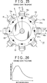
Wie in der offengelegten japanischen Patentanmeldung Nr. 2009-112091 ( JP-A-2009-112091 ) beschrieben, ist eine rotierende elektrische Maschine bekannt, bei der Rotorspulen für einen Rotor vorgesehen sind und durch ein drehendes Magnetfeld Induktionsströme in den Rotorspulen erzeugt werden, um zu bewirken, dass der Rotor ein Drehmoment erzeugt. Das magnetische Drehfeld wird von einem Stator erzeugt und enthält räumliche Harmonische. Außerdem werden mit dieser rotierenden elektrischen Maschine auf wirksame Weise Induktionsströme in den Rotorspulen erzeugt, wodurch bewirkt werden kann, dass das Drehmoment, das auf den Rotor wirkt, wirksam erhöht wird. 23 bis 25 zeigen den schematischen Aufbau der rotierenden elektrischen Maschine, die in JP-A-2009-112091 beschrieben ist. 23 ist eine Ansicht, die den schematischen Aufbau eines Stators und eines Rotors zeigt, die aus einer Richtung betrachtet werden, die parallel ist zur Drehachse des Rotors. 24 zeigt den schematischen Aufbau des Stators. 25 zeigt den schematischen Aufbau des Rotors.As in Japanese Patent Application Laid-open No. 2009-112091 ( JP-A-2009-112091 ), a rotary electric machine is known in which rotor coils are provided for a rotor and induction currents are generated in the rotor coils by a rotating magnetic field to cause the rotor to generate a torque. The rotating magnetic field is generated by a stator and contains spatial harmonics. In addition, with this rotary electric machine, induction currents are effectively generated in the rotor coils, which can cause the torque acting on the rotor to be effectively increased. 23 to 25 show the schematic structure of the rotating electrical machine, which in JP-A-2009-112091 is described. 23 FIG. 12 is a view showing the schematic structure of a stator and a rotor, which are viewed from a direction parallel to the rotational axis of the rotor. 24 shows the schematic structure of the stator. 25 shows the schematic structure of the rotor.
Jedoch besteht im Fall der rotierenden elektrischen Maschine 10, die in 23 bis 25 dargestellt ist, immer noch Raum für Verbesserungen in Bezug auf die effiziente Erhöhung des Drehmoments während eines langsamen Rotierens, wenn die Drehzahl der rotierenden elektrischen Maschine 10 niedrig ist. 26 ist ein Graph, der ein Beispiel für die Beziehung zwischen einer Rotordrehzahl und einem Motordrehmoment in einem Bereich zeigt, in dem die Drehzahl niedrig ist, wenn der gleiche Aufbau wie derjenige der rotierenden elektrischen Maschine, die in 23 bis 25 dargestellt ist, als elektrischer Motor (Motor) verwendet wird. Wie in 26 dargestellt ist, nimmt das Motordrehmoment der rotierenden elektrischen Maschine 10 in dem Bereich, in dem die Drehzahl niedrig ist, deutlich ab. Um es mit Bezug auf 23 bis 25 zu beschreiben, so liegt dies daran, dass in der rotierenden elektrischen Maschine 10 in dem Bereich, in dem die Drehzahl niedrig ist, aber die Schnelligkeit der Schwankung von verketteten Magnetflüssen abnimmt, Rotor-Induktionsströme, die durch Rotorspulen 18n und 18s fließen, von Schwankungen des Magnetfelds wegen der harmonischen Komponenten des von einem Stator 12 erzeugten magnetischen Drehfelds erzeugt werden, während sich Magnetflüsse, die mit den Rotorspulen 18n und 18s verkettet sind, nicht nennenswert ändern, weswegen induzierte elektromotorische Spannungen abnehmen, wodurch die Rotor-Induktionsströme schwächer werden. Daher nimmt das Motordrehmoment während einer Rotation mit niedriger Drehzahl ab. Man beachte, dass in der obigen Beschreibung das Motordrehmoment abnimmt, wenn die rotierende elektrische Maschine 10 als Elektromotor in dem Bereich verwendet wird, in dem die Drehzahl niedrig ist; jedoch kann dann, wenn die rotierende elektrische Maschine 10 als Generator verwendet wird, ein regeneratives Drehmoment im Niedrigdrehzahlbereich aus demselben Grund deutlich abnehmen.However, in the case of the rotary electric machine 10 , in the 23 to 25 is still room for improvement in terms of efficiently increasing the torque during a slow rotation when the rotational speed of the rotating electric machine 10 is low. 26 FIG. 12 is a graph showing an example of the relationship between a rotor speed and a motor torque in a region where the rotational speed is low when the same structure as that of the rotary electric machine disclosed in FIG 23 to 25 is shown as an electric motor (motor) is used. As in 26 is shown, takes the motor torque of the rotating electric machine 10 in the range in which the speed is low, significantly from. With respect to it 23 to 25 to describe, this is because in the rotating electric machine 10 in the area where the speed is low, but the speed of fluctuation of chained magnetic fluxes decreases, rotor induction currents passing through rotor coils 18n and 18s flow, from fluctuations in the magnetic field because of the harmonic components of a stator 12 generated magnetic rotating field can be generated while moving magnetic flux with the rotor coils 18n and 18s are not significantly changed, and therefore induced electromotive voltages decrease, thereby weakening the rotor induction currents. Therefore, the engine torque decreases during low speed rotation. Note that in the above description, the motor torque decreases when the rotary electric machine 10 is used as an electric motor in the range in which the rotational speed is low; however, if the rotating electric machine 10 is used as a generator, a regenerative torque in the low speed range for the same reason significantly decrease.
KURZFASSUNG DER ERFINDUNGSUMMARY OF THE INVENTION
Die Erfinder wissen, dass es möglich ist, Impulsstrom über Wechselströme zu legen, die durch Statorspulen geleitet werden sollen, um Induktionsströme zu verstärken, die in Rotorspulen erzeugt werden, um dadurch eine Erhöhung des Drehmoments einer rotierenden elektrischen Maschine auch in einem Bereich niedriger Drehzahlen zu ermöglichen. Jedoch haben die Erfinder gefunden, dass ohne die Entwicklung eines Verfahrens für eine Induktionsstromüberlagerung die Spitzenwerte von Strömen, die durch die Statorspulen fließen, sehr hoch werden und dass dies zu Nachteilen führen kann, beispielsweise zu einer Vergrößerung und Verteuerung eines Steuersystems, das einen Wechselrichter aufweist, bei dem es sich um eine Antriebseinheit für eine rotierende elektrische Maschine handelt.The inventors know that it is possible to apply pulse current through alternating currents to be passed through stator coils to amplify induction currents generated in rotor coils, thereby increasing the torque of a rotary electric machine even in a low-speed range enable. However, the inventors have found that without the development of a method for induction current superposition, the peak values of currents flowing through the stator coils become very high and this can lead to disadvantages, for example, to increase and increase the cost of a control system having an inverter , which is a drive unit for a rotary electric machine.
Im Gegensatz dazu beschreiben die veröffentlichte japanische Patentanmeldung Nr. 2007-185082 ( JP-A-2007-185082 ), die veröffentlichte japanische Patentanmeldung Nr. 2010-98908 ( JP-A-98908 ) und die veröffentlichte japanische Patentanmeldung Nr. 2010-110079 ( JP-A-110079 ) eine Feldwicklungs-Synchronmaschine, für die eine Impulsstromüberlagerung verwendet wird, jedoch beschreiben diese Veröffentlichungen keine Maßnahmen zur Erhöhung eines Drehmoments bei gleichzeitiger Verhinderung von zu starken Stromflüssen durch die Statorspulen.In contrast, Japanese Published Patent Application No. 2007-185082 ( JP-A-2007-185082 ), Japanese Patent Application Publication No. 2010-98908 ( JP-A-98908 ) and Japanese Patent Application Publication No. 2010-110079 ( JP-A-110079 However, these publications do not describe measures for increasing torque while preventing excessive current flows through the stator coils.
Die Erfindung implementiert eine rotierende elektrische Maschine, die in der Lage ist, in einem Antriebssystem für eine rotierende elektrische Maschine ein Drehmoment auch in einem niedrigen Drehzahlbereich zu erhöhen und gleichzeitig zu verhindern, dass zu starke Ströme durch Statorspulen fließen.The invention implements a rotary electric machine capable of increasing torque even in a low speed range in a drive system for a rotary electric machine while preventing excessive currents from flowing through stator coils.
Ein erster Aspekt der Erfindung betrifft ein Antriebssystem einer rotierenden elektrischen Maschine, das aufweist: eine rotierende elektrische Maschine mit einem Stator und einem Rotor, die so angeordnet sind, dass sie einander zugewandt sind; eine Antriebseinheit, welche die rotierende elektrische Maschine antreibt; und eine Steuereinheit, welche die Antriebseinheit steuert. Der Stator weist auf: einen Statorkern mit einer Mehrzahl von Statornuten, die in Umfangsrichtung um eine Drehachse des Rotors voneinander beabstandet sind, und mehrphasige Statorspulen, die in einer konzentrierten Wicklung durch die Statornuten um den Statorkern gewickelt sind; der Rotor weist auf: einen Rotorkern mit einer Mehrzahl von Rotornuten, die in Umfangsrichtung um eine Drehachse des Rotors voneinander beabstandet sind, Rotorspulen, die an mehreren Umfangsrichtungsabschnitten des Rotorkerns auf solche Weise gewickelt sind, dass sie zumindest zum Teil in den Rotornuten angeordnet sind, und eine Gleichrichtereinheit, die mit den Rotorspulen verbunden ist und magnetische Eigenschaften der entsprechenden Rotorspulen unter der Mehrzahl von Rotorspulen in Umfangsrichtung abwechselnd ändert, und der Rotor ändert magnetische Eigenschaften von Magnetpolabschnitten an mehreren Umfangsrichtungsabschnitten in Umfangsrichtung abwechselnd, wobei die magnetischen Eigenschaften durch Ströme erzeugt werden, die durch die jeweiligen Rotorspulen fließen, und die Steuereinheit weist eine Abwärts-/Aufwärtsimpuls-Überlagerungseinheit auf zum Legen eines Abwärtsimpulsstroms für eine impulsförmige Abwärtswandlung über einen q-Achsenstrombefehl, um Ströme durch die Statorspulen zu leiten, um magnetische Feldflüsse in Richtungen zu erzeugen, die in Bezug auf Magnetpolrichtungen, bei denen es sich um Wicklungs-Mittelachsenrichtungen der jeweiligen Rotorspulen handelt, über einem elektrischen Winkel von 90 Grad nach vorne verschoben sind, und die einen Aufwärtsimpulsstrom für eine impulsförmige Aufwärtswandlung über einen d-Achsenstrombefehl legt, um Ströme durch die Statorspulen zu leiten, um magnetische Feldflüsse in den Magnetpolrichtungen zu erzeugen. Man beachte, dass unter einem Abwärtsimpulsstrom ein Impulsstrom zu verstehen ist, der auf impulsförmige Weise steil abfällt und dann steil ansteigt, und dass unter dem Aufwärtsimpulsstrom ein Impulsstrom zu verstehen ist, der auf impulsförmige Weise steil ansteigt und dann steil abfällt. Außerdem kann die Impulswellenform sowohl des Abwärtsimpulsstroms als auch des Aufwärtsimpulsstroms eine Rechteckswelle, eine Dreieckswelle oder eine Wellenform sein, die aus einer Mehrzahl von Kurven und/oder Linien besteht, die eine vorstehende Form bilden. Man beachte, dass „Rotorkern” ein integrales Bauteil im Rotor außer den Rotorspulen bezeichnet, das beispielsweise aus Magneten und einem Rotorkernkörper, der aus magnetischem Material gebildet ist, bestehen kann. Außerdem sind die „Rotornuten” nicht auf Abschnitte beschränkt, die eine Kerbenform haben und die zur Randfläche des Rotorkerns hin offen sind, und schließen beispielsweise auch Schlitze ein, die nicht zur Randfläche des Rotorkerns hin offen sind und die so ausgebildet sind, dass sie in der axialen Richtung innen durch den Rotorkern verlaufen. A first aspect of the invention relates to a drive system of a rotary electric machine, comprising: a rotary electric machine having a stator and a rotor arranged so as to face each other; a drive unit that drives the rotary electric machine; and a control unit that controls the drive unit. The stator includes: a stator core having a plurality of stator slots circumferentially spaced about an axis of rotation of the rotor and multi-phase stator coils wound in a concentrated winding through the stator slots about the stator core; the rotor includes: a rotor core having a plurality of rotor slots circumferentially spaced about an axis of rotation of the rotor, rotor coils wound on a plurality of circumferential direction portions of the rotor core in such a manner as to be at least partially disposed in the rotor slots; and a rectifier unit that is connected to the rotor coils and alternately alternately changes magnetic properties of the respective rotor coils among the plurality of rotor coils in the circumferential direction, and the rotor alternately alternately changes magnetic properties of magnetic pole portions at a plurality of circumferential direction portions in the circumferential direction, generating the magnetic characteristics by currents; which flow through the respective rotor coils, and the control unit has a step-down / step-up superimposing unit for applying a step-down pulse current for a step-down pulse-down via a q-axis current command to currents to conduct the stator coils to generate magnetic field fluxes in directions which are shifted forward with respect to magnetic pole directions, which are winding center axis directions of the respective rotor coils, through an electrical angle of 90 degrees and which provides an upward pulse current for one provides pulse-shaped up-conversion across a d-axis current command to conduct currents through the stator coils to generate magnetic field fluxes in the magnetic pole directions. Note that a down-pulse current is to be understood as a pulse current that drops steeply in a pulse-like manner and then rises steeply, and that the up-pulse current is a pulse current that rises sharply in a pulse-like manner and then drops steeply. In addition, the pulse waveform of both the down-pulse current and the up-pulse current may be a rectangular wave, a triangular wave, or a waveform consisting of a plurality of curves and / or lines forming a protruding shape. Note that "rotor core" refers to an integral component in the rotor other than the rotor coils, which may be made of, for example, magnets and a rotor core body formed of magnetic material. In addition, the "rotor grooves" are not limited to portions having a notch shape and which are open to the edge surface of the rotor core, and include, for example, slots that are not open to the edge surface of the rotor core and that are formed so that in the axial direction inside through the rotor core.
Mit dem Antriebssystem einer rotierenden elektrischen Maschine kann eine rotierende elektrische Maschine verwirklicht werden, die in der Lage ist, auch in einem niedrigen Drehzahlbereich ein Drehmoment zu erhöhen und gleichzeitig zu verhindern, dass zu starke Ströme durch die Statorspulen fließen. Das heißt, durch Überlagern des q-Achsenstrombefehls mit einem Abwärtsimpulsstrom und durch Überlagern des d-Achsenstrombefehls mit einem Aufwärtsimpulsstrom können Induktionsströme, die in den Rotorspulen auftreten, verstärkt werden, während bewirkt wird, dass Ströme aller drei Phasen im erforderlichen Strombeschränkungsbereich liegen. Außerdem wird ein Aufwärtsimpulsstrom über den d-Achsenstrombefehl gelegt, so dass es möglich ist, den Umfang von Schwankungen von Magnetflüssen, die durch die d-Achsenmagnetpfade fließen, die vom d-Achsenstrombefehl erzeugt werden, zu verstärken. Die d-Achsenmagnetpfade sind in der Lage, den Durchgang von Magnetflüssen durch einen Luftspalt im Vergleich zu den q-Achsenmagnetpfaden, die dem q-Achsenstrombefehl entsprechen, zu verringern, wodurch der magnetische Widerstand abnimmt. Daher ist die Erhöhung des Schwankungsumfangs in d-Achsenmagnetflüssen wirksam zur Verstärkung des Drehmoments. Somit ist es möglich, Induktionsströme, die in den Rotorspulen erzeugt werden, auch in einem Bereich niedriger Drehzahl zu verstärken, während die Spitzen von Statorströmen aller Phasen niedrig gehalten werden, daher ist es möglich, das Drehmoment der rotierenden elektrischen Maschine zu verstärken.With the drive system of a rotary electric machine, a rotary electric machine capable of increasing a torque even in a low speed range while preventing excessive currents from flowing through the stator coils can be realized. That is, by superimposing the q-axis current command on a down pulse current and superimposing the d-axis current command on an upward pulse current, induction currents occurring in the rotor coils can be amplified while causing currents of all three phases to be within the required current restriction range. In addition, an upward pulse current is applied across the d-axis current command, so that it is possible to enhance the amount of fluctuation of magnetic fluxes flowing through the d-axis magnetic paths generated from the d-axis current command. The d-axis magnetic paths are capable of reducing the passage of magnetic fluxes through an air gap as compared with the q-axis magnetic paths corresponding to the q-axis current command, whereby the magnetic resistance decreases. Therefore, the increase of the fluctuation amount in d-axis magnetic fluxes is effective for enhancing the torque. Thus, it is possible to amplify induction currents generated in the rotor coils even in a low-speed region while keeping the peaks of stator currents of all phases low, therefore, it is possible to enhance the torque of the rotary electric machine.
Die Abwärts-/Aufwärtsimpuls-Überlagerungseinheit kann den Aufwärtsimpulsstrom über den d-Achsenstrombefehl legen und den Abwärtsimpulsstrom nicht über den q-Achsenstrombefehl legen, wenn ein Ausgangsdrehmoment der rotierenden elektrischen Maschine unter oder bei einem Schwellenwert liegt, und kann den Aufwärtsimpulsstrom über den d-Achsenstrombefehl legen und den Abwärtsimpulsstrom über den q-Achsenstrombefehl legen, wenn das Ausgangsdrehmoment den Schwellenwert übersteigt.The down / up pulse superimposing unit may apply the upward pulse current over the d-axis current command and not apply the down pulse current over the q-axis current command when output torque of the rotary electric machine is below or at a threshold value, and may increase the upward pulse current via the d-axis current command and apply the step-down pulse current across the q-axis current command if the output torque exceeds the threshold.
Die Abwärts-/Aufwärtsimpulsstrom-Überlagerungseinheit kann den Abwärtsimpulsstrom über den q-Achsenstrombefehl legen und kann den Aufwärtsimpulsstrom über den d-Achsenstrombefehl legen, so dass ein Stromvektor nach Überlagerung von Statorströmen, die durch die Statorspulen geleitet werden sollen, mit dem Impulsstrom in einem Steuerzirkelkreis liegt, der von einem distalen Ende eines Stromvektors beschrieben wird, der in einem d-q-Koordinatensystem definiert ist, wenn der Impulsstrom nicht über die Statorströme gelegt wird.The down / up pulse current superimposing unit may apply the down pulse current over the q-axis current command and may apply the upward pulse current over the d-axis current command such that a current vector, after superposition of stator currents to be passed through the stator coils, with the pulse current in a control circular circuit which is described by a distal end of a current vector which is in a dq- Coordinate system is defined when the pulse current is not applied across the stator currents.
Jede von den Rotorspulen kann mit irgendeinem von den Gleichrichterelementen verbunden sein, die als Gleichrichtereinheit dienen und deren Vorwärtsrichtungen zwischen irgendwelchen zwei in der Umfangsrichtung des Rotors benachbarten Rotorspulen einander entgegengesetzt sind, und die Gleichrichterelemente können Ströme gleichrichten, die durch induzierte elektromotorische Kräfte erzeugt werden und durch die Rotorspulen fließen sollen, um dadurch Phasen von Strömen, die durch irgendwelche zwei in der Umfangsrichtung benachbarte Rotorspulen fließen, zwischen einer A-Phase und einer B-Phase abwechselnd zu ändern.Each of the rotor coils may be connected to any one of the rectifier elements serving as a rectifier unit and whose forward directions are opposed to each other between any two rotor coils adjacent in the circumferential direction of the rotor, and the rectifier elements can rectify currents generated by induced electromotive forces the rotor coils are to flow to thereby alternately change phases of currents flowing through any two circumferentially adjacent rotor coils between an A phase and a B phase.
Die Gleichrichterelemente können ein erstes Gleichrichterelement und ein zweites Gleichrichterelement sein, die jeweils mit den entsprechenden Rotorspulen verbunden sind, und das erste Gleichrichterelement und das zweite Gleichrichterelement können unabhängig voneinander Ströme, die aufgrund der erzeugten induzierten elektromotorischen Kräfte erzeugt werden, gleichrichten, so dass die gleichgerichteten Ströme durch die entsprechenden Rotorspulen fließen, und können die magnetischen Eigenschaften der Magnetpolabschnitte an mehreren Umfangsrichtungsabschnitten in Umfangsrichtung abwechselnd ändern, wobei die magnetischen Eigenschaften durch Ströme erzeugt werden, die durch die entsprechenden Rotorspulen fließen.The rectifying elements may be a first rectifying element and a second rectifying element respectively connected to the respective rotor coils, and the first rectifying element and the second rectifying element may independently rectify currents generated due to the induced induced electromotive forces, so that the rectified ones Currents flow through the respective rotor coils, and can alternately change the magnetic properties of the magnetic pole portions at a plurality of circumferential direction portions in the circumferential direction, the magnetic characteristics being generated by currents flowing through the respective rotor coils.
Der Rotorkern kann ausgeprägte bzw. Schenkelpole aufweisen, bei denen es sich um die Mehrzahl von Magnetpolabschnitten handelt, die bezogen auf die Umfangsrichtung des Rotors mit Abständen zueinander angeordnet sind und zum Stator hin vorstehen, und die Schenkelpole können magnetisiert werden, wenn Ströme, die von der Gleichrichtereinheit gleichgerichtet werden, durch die Rotorspulen fließen, um dadurch als Magnete zu fungieren, die feste Magnetpole aufweisen.The rotor core may have salient poles, which are the plurality of magnetic pole portions spaced apart from each other with respect to the circumferential direction of the rotor and projecting toward the stator, and the salient poles may be magnetized when currents flowing from of the rectifier unit, through which the rotor coils flow, to thereby function as magnets having fixed magnetic poles.
Der Rotorkern kann Schenkelpole aufweisen, bei denen es sich um die Mehrzahl von Magnetpolabschnitten handelt, die bezogen auf die Umfangsrichtung des Rotorkerns mit Abständen zueinander angeordnet sind und zum Stator hin vorstehen, und die Schenkelpole können magnetisiert werden, wenn Ströme, die von der Gleichrichtereinheit gleichgerichtet werden, durch die Rotorspulen fließen, um dadurch als Magnete zu fungieren, die feste Magnetpole aufweisen, und der Rotor kann ferner Hilfsrotorspulen aufweisen, die an proximalen Abschnitten der jeweiligen Schenkelpole gewickelt sind, irgendwelche zwei von den Hilfsrotorspulen, die um irgendwelche zwei in der Umfangsrichtung des Rotors benachbarte Schenkelpole gewickelt sind, können in Reihe miteinander verbunden sein, um einen Hilfs-Spulensatz zu bilden, und die einen Enden von irgendwelchen zwei benachbarten Rotorspulen, die um irgendwelche zwei bezogen auf die Umfangsrichtung des Rotors benachbarte Schenkelpole gewickelt sind, können an einem Verbindungspunkt über die jeweils entsprechenden Gleichrichterelemente miteinander verbunden sein, so dass die jeweils entsprechenden Gleichrichterelemente einander aus entgegengesetzten Richtungen zugewandt sind, die anderen Enden der irgendwelchen zwei benachbarten Rotorspulen, die um irgendwelche zwei in der Umfangsrichtung des Rotors benachbarte Schenkelpole gewickelt sind, können mit einem Ende des Hilfs-Spulensatzes verbunden sein, und der Verbindungspunkt kann mit dem anderen Ende des Hilfs-Spulensatzes verbunden sein.The rotor core may have salient poles, which are the plurality of magnetic pole portions spaced apart from each other with respect to the circumferential direction of the rotor core and projecting toward the stator, and the salient poles may be magnetized when currents rectified by the rectifier unit are allowed to flow through the rotor coils to thereby function as magnets having fixed magnetic poles, and the rotor may further comprise auxiliary rotor coils wound at proximal portions of the respective salient poles, any two of the auxiliary rotor coils spaced any two in the circumferential direction of the rotor adjacent salient poles may be connected in series with each other to form an auxiliary coil set, and the one ends of any two adjacent rotor coils wound around any two salient poles adjacent to the circumferential direction of the rotor may be connected to e At the connection point, the respective rectifier elements are connected to each other from opposite directions, the other ends of any two adjacent rotor coils wound around any two salient poles adjacent to each other in the circumferential direction of the rotor can be connected to one another Be connected to the end of the auxiliary coil set, and the connection point may be connected to the other end of the auxiliary coil set.
Eine Breite jedes Schenkelpols in der Umfangsrichtung des Rotors kann kleiner sein als eine Breite, die einem elektrischen Winkel von 180° entspricht, und jede von den Rotorspulen kann mit verkürzter Schrittweite um einen der Schenkelpole gewickelt sein.A width of each salient pole in the circumferential direction of the rotor may be smaller than a width corresponding to an electrical angle of 180 °, and each of the rotor coils may be wound at a short pitch about one of the salient poles.
Eine Breite jeder Rotorspule in der Umfangsrichtung des Rotors kann einer Breite gleich sein, die einem elektrischen Winkel von 90° entspricht.A width of each rotor coil in the circumferential direction of the rotor may be equal to a width corresponding to an electrical angle of 90 °.
Mit dem Antriebssystem einer rotierenden elektrischen Maschine gemäß dem Aspekt der Erfindung kann die rotierende elektrische Maschine verwirklicht werden, die in der Lage ist, ein Drehmoment auch in einem niedrigen Drehzahlbereich zu erhöhen, während sie gleichzeitig verhindert, dass zu starke Ströme durch die Statorspulen fließen.With the drive system of a rotary electric machine according to the aspect of the invention, the rotary electric machine capable of increasing a torque even in a low speed range can be realized while at the same time preventing excessive currents from flowing through the stator coils.
KURZE BESCHREIBUNG DER ZEICHNUNGENBRIEF DESCRIPTION OF THE DRAWINGS
Merkmale und Vorteile sowie die technische und industrielle Bedeutung von Ausführungsbeispielen der Erfindung werden nachstehend mit Bezug auf die begleitenden Zeichnungen beschrieben, in denen gleiche Bezugszahlen gleiche Elemente bezeichnen, und in denen:Features and advantages as well as the technical and industrial significance of embodiments of the invention will be described below with reference to the accompanying drawings, in which like numerals denote like elements, and in which:
1 eine Ansicht ist, die einen schematischen Aufbau eines Antriebssystems einer rotierenden elektrischen Maschine gemäß einer Ausführungsform der Erfindung zeigt; 1 is a view showing a schematic structure of a drive system of a rotary electric machine according to an embodiment of the invention;
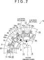
2 eine schematische Ansicht ist, die einen Teil eines Abschnitts zeigt, in dem ein Stator einem Rotor in einer Ausführungsform der Erfindung zugewandt ist; 2 Fig. 12 is a schematic view showing a part of a portion in which a stator faces a rotor in an embodiment of the invention;
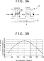
3A eine schematische Ansicht ist, die einen Zustand zeigt, in dem ein Magnetfluss in dem Rotor in der Ausführungsform der Erfindung verläuft; 3A Fig. 12 is a schematic view showing a state in which a magnetic flux passes in the rotor in the embodiment of the invention;
3B ein Graph ist, der das Ergebnis zeigt, das durch Berechnen der Amplitude eines mit einer Rotorspule verketteten Magnetflusses erhalten wird, während die Umfangsichtungsbreite θ der Rotorspule in der rotierenden elektrischen Maschine, die in 2 dargestellt ist, geändert wird; 3B FIG. 12 is a graph showing the result obtained by calculating the amplitude of a magnetic flux interlinked with a rotor coil, while the circumferential sighting width θ of the rotor coil in the rotary electric machine shown in FIG 2 is changed;
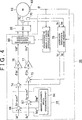
4 ein Blockschema ist, das den Aufbau eines Controllers in der Ausführungsform der Erfindung zeigt; 4 Fig. 12 is a block diagram showing the construction of a controller in the embodiment of the invention;
5A ein Zeitschema ist, das ein Beispiel für zeitabhängige Veränderungen in Statorströmen unter Verwendung eines überlagerten d-Achsenstrombefehlswerts Idsum*, eines überlagerten q-Achsenstrombefehlswerts Iqsum* und jedes Phasenstroms in der Ausführungsform der Erfindung zeigt; 5A Fig. 12 is a timing chart showing an example of time-dependent changes in stator currents using a superimposed d-axis current command value Idsum *, a superimposed q-axis current command value Iqsum *, and each phase current in the embodiment of the invention;
5B ein Zeitschema ist, das eine zeitabhängige Veränderung von Rotorstrom, der in den Rotorspulen erzeugt wird, entsprechend 5A zeigt; 5B is a timing diagram corresponding to a time-dependent variation of rotor current generated in the rotor coils 5A shows;
6 ein Zeitschema ist, das Zeitpunkte t1 und t2 darstellt, zu denen mit der Überlagerung von Dreiphasen-Statorströmen mit Impulsstrom in der Ausführungsform der Erfindung begonnen wird; 6 Fig. 12 is a timing chart showing timings t1 and t2 at which the superposition of three-phase stator currents with pulse current is started in the embodiment of the invention;
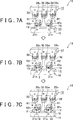
7A eine schematische Ansicht ist, die einen Zustand zeigt, in dem Magnetflüsse durch den Stator und den Rotor verlaufen, wenn ein q-Achsenstrom in der Ausführungsform der Erfindung auf einen festen Wert eingestellt ist; 7A Fig. 12 is a schematic view showing a state in which magnetic fluxes pass through the stator and the rotor when a q-axis current in the embodiment of the invention is set to a fixed value;
7B eine schematische Ansicht ist, die einen Zustand zeigt, in dem Magnetflüsse in einer ersten Halbperiode durch den Stator und den Rotor fließen, wenn ein Abwärtsimpulsstrom über einen q-Achsenstrom gelegt wird; 7B Fig. 12 is a schematic view showing a state in which magnetic fluxes flow through the stator and the rotor in a first half-period when a step-down pulse current is applied across a q-axis current;
7C eine schematische Ansicht ist, die einen Zustand zeigt, in dem Magnetflüsse in einer zweiten Halbperiode durch den Stator und den Rotor fließen, wenn ein Abwärtsimpulsstrom über einen q-Achsenstrom gelegt wird; 7C Fig. 12 is a schematic view showing a state in which magnetic fluxes flow through the stator and the rotor in a second half period when a down pulse current is applied across a q-axis current;
8 eine schematische Ansicht ist, die einen Zustand zeigt, wo Magnetflüsse wegen des d-Achsenstroms durch den Stator und den Rotor in der Ausführungsform der Erfindung fließen; 8th Fig. 12 is a schematic view showing a state where magnetic fluxes flow through the stator and the rotor in the embodiment of the invention because of the d-axis current;
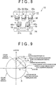
9 ein Graph ist, der Stromvektoren vor und nach der Überlagerung mit Impulsstrom in der Ausführungsform der Erfindung zeigt; 9 Fig. 10 is a graph showing current vectors before and after superposition with pulse current in the embodiment of the invention;
10 ein Graph ist, der die Beziehung zwischen der Drehzahl und dem Drehmoment der rotierenden elektrischen Maschine zur Darstellung eines Beispiels zeigt, in dem ein Impulsstrom-Überlagerungszustand in der Ausführungsform der Erfindung geändert wird; 10 Fig. 12 is a graph showing the relationship between the rotational speed and the torque of the rotary electric machine for illustrating an example in which a pulse current superimposition state is changed in the embodiment of the invention;
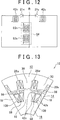
11 eine Ansicht ist, die eine andere Ausführungsform der Erfindung zeigt und die 3A entspricht; 11 is a view showing another embodiment of the invention and the 3A corresponds;
12 eine Ansicht ist, die eine Ersatzschaltung von Rotorspulen und Hilfsrotorspulen in der Ausführungsform von 11 zeigt; 12 FIG. 12 is a view showing an equivalent circuit of rotor coils and auxiliary rotor coils in the embodiment of FIG 11 shows;
13 eine schematische Querschnitts-Teilansicht ist, die einen Abschnitt, in dem ein Stator einem Rotor zugewandt ist, in einer anderen Ausführungsform der Erfindung zeigt; 13 is a schematic cross-sectional partial view showing a portion in which a stator faces a rotor, in another embodiment of the invention;
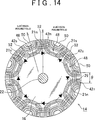
14 eine schematische Ansicht ist, die einen Rotor eines anderen Gestaltungsbeispiels der rotierenden elektrischen Maschine zeigt, welche die Ausführungsform der Erfindung darstellt; 14 Fig. 12 is a schematic view showing a rotor of another design example of the rotary electric machine which is the embodiment of the invention;
15 eine schematische Ansicht ist, die einen Rotor eines anderen Gestaltungsbeispiels der rotierenden elektrischen Maschine zeigt, welche die Ausführungsform der Erfindung darstellt; 15 Fig. 12 is a schematic view showing a rotor of another design example of the rotary electric machine which is the embodiment of the invention;
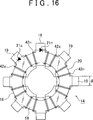
16 eine schematische Ansicht ist, die einen Rotor eines anderen Gestaltungsbeispiels der rotierenden elektrischen Maschine zeigt, welche die Ausführungsform der Erfindung darstellt; 16 Fig. 12 is a schematic view showing a rotor of another design example of the rotary electric machine which is the embodiment of the invention;
17 eine schematische Ansicht ist, die ein anderes Gestaltungsbeispiel der rotierenden elektrischen Maschine zeigt, welche die Ausführungsform der Erfindung darstellt, betrachtet in der Richtung, die parallel ist zur Drehachse des Rotors; 17 Fig. 12 is a schematic view showing another configuration example of the rotary electric machine which is the embodiment of the invention, viewed in the direction parallel to the rotational axis of the rotor;
18 eine schematische Ansicht ist, die den Rotor des Gestaltungsbeispiels von 17 darstellt; 18 is a schematic view showing the rotor of the design example of 17 represents;
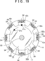
19 eine schematische Ansicht ist, die einen Rotor eines anderen Gestaltungsbeispiels der rotierenden elektrischen Maschine zeigt, welche die Ausführungsform der Erfindung darstellt; 19 Fig. 12 is a schematic view showing a rotor of another design example of the rotary electric machine which is the embodiment of the invention;
20 eine schematische Ansicht ist, die einen Rotor eines anderen Gestaltungsbeispiels der rotierenden elektrischen Maschine zeigt, welche die Ausführungsform der Erfindung darstellt; 20 Fig. 12 is a schematic view showing a rotor of another design example of the rotary electric machine which is the embodiment of the invention;
21 eine schematische Ansicht ist, die einen Rotor eines anderen Gestaltungsbeispiels der rotierenden elektrischen Maschine zeigt, welche die Ausführungsform der Erfindung darstellt; 21 Fig. 12 is a schematic view showing a rotor of another design example of the rotary electric machine which is the embodiment of the invention;
22 eine schematische Ansicht ist, die einen Rotor eines anderen Gestaltungsbeispiels der rotierenden elektrischen Maschine zeigt, welche die Ausführungsform der Erfindung darstellt; 22 Fig. 12 is a schematic view showing a rotor of another design example of the rotary electric machine which is the embodiment of the invention;
23 eine Ansicht ist, die den schematischen Aufbau eines Stators und eines Rotors zeigt, die aus einer Richtung betrachtet werden, die parallel ist zur Drehachse des Rotors, in einer existierenden rotierenden elektrischen Maschine; 23 is a view showing the schematic structure of a stator and a rotor, which are viewed from a direction parallel is the axis of rotation of the rotor, in an existing rotating electrical machine;
24 eine Ansicht ist, die den schematischen Aufbau des Stators in der rotierenden elektrischen Maschine von 23 darstellt; 24 is a view showing the schematic structure of the stator in the rotating electric machine of 23 represents;
25 eine Ansicht ist, die den schematischen Aufbau des Stators in der rotierenden elektrischen Maschine von 23 darstellt; und 25 is a view showing the schematic structure of the stator in the rotating electric machine of 23 represents; and
26 ein Graph ist, der ein Beispiel für die Beziehung zwischen einer Rotordrehzahl und einem Motordrehmoment in dem gleichen Aufbau wie dem der rotierenden elektrischen Maschine von 23 darstellt. 26 FIG. 12 is a graph showing an example of the relationship between a rotor speed and a motor torque in the same structure as that of the rotary electric machine of FIG 23 represents.
AUSFÜHRLICHE BESCHREIBUNG VON AUSFÜHRUNGSFORMENDETAILED DESCRIPTION OF EMBODIMENTS
1 bis 8 und 10 sind Ansichten, die eine Ausführungsform der Erfindung darstellen. 1 ist eine Ansicht, die den schematischen Aufbau eines Antriebssystems einer rotierenden elektrischen Maschine gemäß der Ausführungsform zeigt. 2 ist eine schematische Ansicht, die einen Teil eines Abschnitts zeigt, in dem ein Stator einem Rotor in der Ausführungsform zugewandt ist. 3A ist eine schematische Ansicht, die einen Zustand zeigt, in dem ein Magnetfluss durch den Rotor in der Ausführungsform fließt. 3B ist ein Graph, der das Ergebnis zeigt, das durch Berechnen der Amplitude eines Magnetflusses, der mit einer Rotorspule verkettet ist, erhalten wird, während die Umfangsichtungsbreite θ der Rotorspule geändert wird, in der rotierenden elektrischen Maschine, die in 2 dargestellt ist. 4 ist ein Blockschema, das den Aufbau eines Controllers in der Ausführungsform zeigt. Wie in 1 dargestellt ist, weist ein Antriebssystem 34 einer rotierenden elektrischen Maschine gemäß der Ausführungsform eine rotierende elektrische Maschine 10, einen Wechselrichter 36, einen Controller 38 und eine elektrische Speichervorrichtung 40 auf. Der Wechselrichter 36 ist eine Antriebseinheit, die die rotierende elektrische Maschine 10 antreibt. Der Controller 38 ist eine Steuereinheit, die den Wechselrichter 36 steuert. Die elektrische Speichervorrichtung 40 ist eine Leistungsquelle. Das Antriebssystem 34 einer rotierenden elektrischen Maschine treibt die rotierende elektrische Maschine 10 an. Außerdem weist die elektrische Maschine 10, die als ein Elektromotor oder als ein Generator dient, einen Stator 12 und einen Rotor 14 auf, wie in 2 dargestellt ist. Der Stator 12 ist an einem (nicht dargestellten) Gehäuse festgelegt. Der Rotor 14 ist bezogen auf die radiale Richtung weiter innen als der Stator 12 so angeordnet, dass er dem Stator 12 mit einer vorgegebenen Lücke dazwischen zugewandt ist, und kann sich in Bezug auf den Stator 12 drehen. Man beachte, dass „radiale Richtung” eine Ausstrahlungsrichtung bedeutet, die senkrecht ist zur Drehachse des Rotors (im Folgenden ist die Bedeutung von „radiale Richtung” die gleiche, solange nichts anderes angegeben ist). 1 to 8th and 10 are views illustrating an embodiment of the invention. 1 FIG. 14 is a view showing the schematic structure of a drive system of a rotary electric machine according to the embodiment. FIG. 2 FIG. 12 is a schematic view showing a part of a portion where a stator faces a rotor in the embodiment. FIG. 3A FIG. 12 is a schematic view showing a state in which a magnetic flux flows through the rotor in the embodiment. FIG. 3B FIG. 12 is a graph showing the result obtained by calculating the amplitude of a magnetic flux concatenated with a rotor coil while changing the circumferential vision width θ of the rotor coil in the rotary electric machine disclosed in FIG 2 is shown. 4 Fig. 16 is a block diagram showing the structure of a controller in the embodiment. As in 1 is shown, has a drive system 34 a rotary electric machine according to the embodiment, a rotary electric machine 10 , an inverter 36 , a controller 38 and an electrical storage device 40 on. The inverter 36 is a drive unit that drives the rotating electrical machine 10 drives. The controller 38 is a control unit that controls the inverter 36 controls. The electrical storage device 40 is a source of power. The drive system 34 a rotating electric machine drives the rotating electrical machine 10 at. In addition, the electric machine points 10 , which serves as an electric motor or as a generator, a stator 12 and a rotor 14 on, like in 2 is shown. The stator 12 is fixed to a housing (not shown). The rotor 14 is more inward than the stator with respect to the radial direction 12 arranged so that it is the stator 12 with a given gap in between, and may be in relation to the stator 12 rotate. Note that "radial direction" means an irradiation direction perpendicular to the rotation axis of the rotor (hereinafter, the meaning of "radial direction" is the same unless otherwise specified).
Außerdem weist der Stator 12 einen Statorkern 26 und mehrphasige (genauer zum Beispiel dreiphasige, d. h. U-Phasen-, V-Phasen- und W-Phasen-) Statorspulen 28u, 28v und 28w auf. Der Statorkern 26 besteht aus einem magnetischen Material. Die Statorspulen 28u, 28v und 28w sind am Statorkern 26 angeordnet. Zähne 30 sind an mehreren Umfangsrichtungsabschnitten des Statorkerns 26 angeordnet. Die Zähne 30 sind eine Mehrzahl von Statorzähnen, die bezogen auf die radiale Richtung zur Innenseite vorstehen (zum Rotor 14 (23)). Eine Nut 31, bei der es sich um eine Statornut handelt, ist jeweils zwischen benachbarten Zähnen 30 ausgebildet. Man beachte, dass „Umfangsrichtung” eine Richtung entlang des Kreises bedeutet, der um die zentrale Drehachse des Rotors beschrieben wird (im Folgenden ist die Bedeutung von „Umfangsrichtung” gleich, wenn nicht etwas anderes angegeben ist).In addition, the stator points 12 a stator core 26 and polyphase (more specifically, for example, three-phase, ie, U-phase, V-phase, and W-phase) stator coils 28u . 28v and 28w on. The stator core 26 consists of a magnetic material. The stator coils 28u . 28v and 28w are on the stator core 26 arranged. teeth 30 are at a plurality of circumferential direction portions of the stator core 26 arranged. The teeth 30 are a plurality of stator teeth projecting toward the inside with respect to the radial direction (to the rotor 14 ( 23 )). A groove 31 , which is a stator slot, is between each adjacent teeth 30 educated. Note that "circumferential direction" means a direction along the circle described around the central axis of rotation of the rotor (hereinafter, the meaning of "circumferential direction" is the same unless otherwise specified).
Das heißt, die Mehrzahl von Zähnen 30, die bezogen auf die radiale Richtung zur Innenseite (zum Rotor 14) vorstehen, sind auf der Innenrandfläche des Statorkerns 26 bezogen auf die Umfangsrichtung mit Abständen zueinander um die zentrale Drehachse angeordnet, bei der es sich um die Drehachse des Rotors 14 handelt, und die Nuten 31, die jeweils zwischen benachbarten Zähnen 30 ausgebildet sind, sind bezogen auf die Umfangsrichtung mit Abständen zueinander ausgebildet. Das heißt, der Statorkern 26 weist eine Mehrzahl von Nuten 31 auf, die bezogen auf die Umfangsrichtung mit Abständen zueinander um die Drehachse des Rotors 14 ausgebildet sind.That is, the majority of teeth 30 , which relative to the radial direction to the inside (to the rotor 14 ) protrude on the inner peripheral surface of the stator core 26 arranged with respect to the circumferential direction at intervals to each other around the central axis of rotation, which is about the axis of rotation of the rotor 14 trades, and the grooves 31 , each between adjacent teeth 30 are formed, are formed with respect to the circumferential direction with distances from each other. That is, the stator core 26 has a plurality of grooves 31 on, with respect to the circumferential direction with distances from each other about the axis of rotation of the rotor 14 are formed.
Die dreiphasigen Statorspulen 28u, 28v und 28w sind mit verkürzter Schrittweite konzentriert durch die Nuten 31 um die entsprechenden Zähne 30 des Statorkerns 26 gewickelt. Auf diese Weise sind die Statorspulen 28u, 28v und 28w um die entsprechenden Zähne 30 gewickelt, um Magnetpole zu bilden. Weiter werden mehrphasige Wechselströme durch die mehrphasigen Statorspulen 28u, 28v und 28w geschickt, um die Zähne 30, die in der Umfangsrichtung auf einer Linie liegen, zu magnetisieren. Dadurch können magnetische Drehfelder, die in der Umfangsrichtung drehen, im Stator 12 erzeugt werden. Man beachte, dass die Statorspulen aufbaumäßig nicht so beschränkt sind, dass die Statorspulen auf diese Weise um die entsprechenden Zähne des Stators gewickelt sind; die Statorspulen können auch auf andere Weise als um die Zähne um den Statorkern gewickelt sein.The three-phase stator coils 28u . 28v and 28w are concentrated with shortened pitch through the grooves 31 around the corresponding teeth 30 of the stator core 26 wound. In this way, the stator coils 28u . 28v and 28w around the corresponding teeth 30 wrapped to form magnetic poles. Furthermore, polyphase alternating currents are passed through the polyphase stator coils 28u . 28v and 28w sent to the teeth 30 to magnetize in the circumferential direction on a line. This allows rotating magnetic fields that rotate in the circumferential direction in the stator 12 be generated. Note that the stator coils are not structurally limited so that the stator coils are wound around the corresponding teeth of the stator in this manner; the stator coils may also be wound around the stator core other than around the teeth.
Die drehenden Magnetfelder, die in den Zähnen 30 gebildet werden, werden von den distalen Endflächen der Zähne 30 aus an den Rotor 14 angelegt. In dem in 2 dargestellten Beispiel wird ein Polpaar aus den drei Zähnen 30 gebildet, um die jeweils die dreiphasigen (U-Phasen-, V-Phasen- und W-Phasen-)Statorspulen 28u, 28v und 28w gewickelt sind.The rotating magnetic fields in the teeth 30 are formed by the distal end surfaces of the teeth 30 off to the rotor 14 created. In the in 2 example shown is a pair of poles from the three teeth 30 formed around each of the three-phase (U-phase, V-phase and W-phase) stator coils 28u . 28v and 28w are wound.
Außerdem weist der Rotor 14 einen Rotorkern 16, der aus einem magnetischen Material besteht, und eine Mehrzahl von Rotorspulen 42n und 42s auf. Zähne 19 sind an mehreren Umfangrichtungsabschnitten der Außenrandfläche des Rotorkerns 16 so vorgesehen, dass sie in der radialen Richtung zur Außenseite (zum Stator 12) vorstehen, und sind mit Abständen zueinander entlang der Außenrandfläche des Rotorkerns 16 angeordnet. Die Zähne 19 sind eine Mehrzahl von Magnetpolabschnitten (Vorsprünge und Schenkelpole) und sind Rotorzähne. Die Zähne 19 sind dem Stator 12 zugewandt. Außerdem sind Nuten 20, von denen jede eine Rotornut zwischen jeweils benachbarten Zähnen 19 des Rotorkerns 16 ist, bezogen auf die Umfangsrichtung mit Abständen zueinander ausgebildet. Das heißt, der Rotorkern 16 weist die Mehrzahl von Nuten 20 auf, die bezogen auf die Umfangsrichtung mit Abständen zueinander um die Drehachse des Rotors 14 ausgebildet sind.In addition, the rotor points 14 a rotor core 16 which is made of a magnetic material, and a plurality of rotor coils 42n and 42s on. teeth 19 are at a plurality of circumferential direction portions of the outer peripheral surface of the rotor core 16 provided so as to be in the radial direction to the outside (to the stator 12 ) and spaced apart along the outer peripheral surface of the rotor core 16 arranged. The teeth 19 are a plurality of magnetic pole portions (protrusions and salient poles) and are rotor teeth. The teeth 19 are the stator 12 facing. There are also grooves 20 each of which has a rotor groove between each adjacent teeth 19 of the rotor core 16 is formed with respect to the circumferential direction with distances from each other. That is, the rotor core 16 has the plurality of grooves 20 on, with respect to the circumferential direction with distances from each other about the axis of rotation of the rotor 14 are formed.
Wegen der Zähne 19 ändern sich magnetische Widerstände in dem Fall, wo Magnetflüsse vom Stator 12 (von den Zähnen 30) aus verlaufen, mit der Drehrichtung des Rotors 14. Ein magnetischer Widerstand ist an der Position der einzelnen Zähne 19 niedrig, und ein magnetischer Widerstand ist an der Position zwischen jeweils benachbarten Zähnen 19 hoch. Weiter sind die Rotorspulen 42n und 42s so um diese Zähne 19 gewickelt, dass die Rotorspulen 42n und die Rotorspulen 42s in der Umfangsrichtung abwechselnd ausgerichtet sind. Hierbei fällt die Wicklungsmittelachse von jeder der Rotorspulen 42n und 42s mit der radialen Richtung zusammen.Because of the teeth 19 Magnetic resistances change in the case where magnetic fluxes from the stator 12 (from the teeth 30 ) run out, with the direction of rotation of the rotor 14 , A magnetic resistance is at the position of the individual teeth 19 low, and a magnetic resistance is at the position between each adjacent teeth 19 high. Next are the rotor coils 42n and 42s so around those teeth 19 wrapped that the rotor coils 42n and the rotor coils 42s are alternately aligned in the circumferential direction. In this case, the winding center axis of each of the rotor coils falls 42n and 42s together with the radial direction.
Außerdem sind die in Mehrzahl vorhandenen ersten Rotorspulen 42n durch konzentrierte Wicklung um bezogen auf die Umfangsrichtung des Rotors 14 jeweils übernächste Zähne 19 gewickelt, und die in Mehrzahl vorhandenen Rotorspulen 42 sind durch konzentrierte Wicklung um die jeweils anderen Zähne 19 gewickelt. Die anderen Zähne 19 sind den Zähnen 19, um die die ersten Rotorspulen 42n gewickelt sind, benachbart und es handelt sich dabei um bezogen auf die Umfangsrichtung jeweils übernächste Zähne. Außerdem sind Dioden 21n und 21s mit einer ersten Rotorspulenschaltung 44 bzw. einer zweiten Rotorspulenschaltung 46 verbunden. Die erste Rotorspulenschaltung 46 beinhaltet die Mehrzahl von ersten Rotorspulen 42n. Die zweite Rotorspulenschaltung 46 beinhaltet die Mehrzahl von zweiten Rotorspulen 42s. Das heißt, die in Mehrzahl vorhandenen ersten Rotorspulen 42n, die bezogen auf die Umfangsrichtung des Rotors 14 abwechselnd angeordnet sind, sind miteinander elektrisch in Reihe verbunden und sind endlos verbunden, und die Diode 21n ist an einem Abschnitt zwischen irgendwelchen zwei aus der Mehrzahl von ersten Rotorspulen 42n mit jeder von den ersten Rotorspulen 42n in Reihe verbunden, um dadurch die erste Rotorspulenschaltung 44 zu bilden. Die Diode 21n ist eine Gleichrichtereinheit (ein Gleichrichterelement) und ist eine erste Diode. Die ersten Rotorspulen 42n sind um die Zähne 19 gewickelt, die als die gleichen Magnetpole (Nordpole) fungieren.In addition, the plurality of existing first rotor coils 42n by concentrated winding with respect to the circumferential direction of the rotor 14 in each case the next teeth 19 wound, and the plurality of existing rotor coils 42 are by concentrated winding around each other's teeth 19 wound. The other teeth 19 are the teeth 19 around the first rotor coils 42n are wound, adjacent and it is related to the circumferential direction in each case after next teeth. There are also diodes 21n and 21s with a first rotor coil circuit 44 or a second rotor coil circuit 46 connected. The first rotor coil circuit 46 includes the plurality of first rotor coils 42n , The second rotor coil circuit 46 includes the plurality of second rotor coils 42s , That is, the plurality of first rotor coils 42n related to the circumferential direction of the rotor 14 are arranged alternately, are electrically connected in series with each other and are connected endlessly, and the diode 21n is at a portion between any two of the plurality of first rotor coils 42n with each of the first rotor coils 42n connected in series to thereby the first rotor coil circuit 44 to build. The diode 21n is a rectifier unit (a rectifier element) and is a first diode. The first rotor coils 42n are around the teeth 19 wound, which act as the same magnetic poles (north pole).
Außerdem sind die in Mehrzahl vorhandenen zweiten Rotorspulen 42s miteinander elektrisch in Reihe verbunden und endlos verbunden, und die Diode 21s ist an einem Abschnitt zwischen beliebigen zwei aus der Mehrzahl von zweiten Rotorspulen 42s mit jeder von den zweiten Rotorspulen 42s in Reihe verbunden, um dadurch die zweite Rotorspulenschaltung 46 zu bilden. Die Diode 21s ist eine Gleichrichtereinheit (ein Gleichrichterelement) und ist eine zweite Diode. Die zweiten Rotorspulen 42s sind um die Zähne 19 gewickelt, die als die gleichen Magnetpole (Südpole) fungieren. Außerdem sind die Rotorspulen 42n und 42s, die um bezogen auf die Umfangsrichtung jeweils benachbarte Zähne 19 gewickelt sind (die Magnete mit verschiedenen Magnetpolen bilden), elektrisch gegeneinander isoliert. Auf diese Weise sind die Rotorspulen 42n und 42s an mehreren Umfangsrichtungsabschnitten des Außenrandabschnitts des Rotorkerns 16 auf solche Weise gewickelt, dass sie zum Teil in den entsprechenden Nuten 20 angeordnet sind.In addition, the plurality of second rotor coils are present 42s electrically connected in series and connected endlessly, and the diode 21s is at a portion between any two of the plurality of second rotor coils 42s with each of the second rotor coils 42s connected in series to thereby form the second rotor coil circuit 46 to build. The diode 21s is a rectifier unit (a rectifier element) and is a second diode. The second rotor coils 42s are around the teeth 19 wound, which act as the same magnetic poles (south poles). In addition, the rotor coils 42n and 42s , which in relation to the circumferential direction in each case adjacent teeth 19 are wound (which form magnets with different magnetic poles), electrically isolated from each other. In this way, the rotor coils 42n and 42s at a plurality of circumferential direction portions of the outer edge portion of the rotor core 16 wrapped in such a way that they partly in the corresponding grooves 20 are arranged.
Außerdem sind die Gleichrichtungsrichtungen, in denen Ströme, die durch die Rotorspulen 42n und 42s fließen, jeweils von den Dioden 21n und 21s gleichgerichtet werden, entgegengesetzt, so dass in bezogen auf die Umfangsrichtung jeweils benachbarten Zähnen 19 des Rotors 14 Magnete mit unterschiedlichen Magnetpolen gebildet werden. Das heißt, die Dioden 21n und 21s sind mit den Rotorspulen 42n und 42s jeweils in einander entgegensetzten Richtungen auf solche Weise verbunden, dass die Richtungen von elektrischen Strömen, die jeweils durch irgendwelche zwei in Umfangsrichtung des Rotors 14 benachbarte Rotorspulen 42n und 42s fließen (die Gleichrichtungsrichtungen der jeweiligen Dioden 21n und 21s), das heißt die Vorwärtsrichtungen, einander entgegengesetzt sind. Weiter sorgen die Dioden 21n und 21s jeweils für eine Gleichrichtung von elektrischen Strömen, die wegen der induzierten elektromotorischen Kräfte, die von vom Stator 12 erzeugten drehenden Magnetfeldern, welche räumliche harmonische Schwingungen enthalten, erzeugt werden, durch die entsprechenden Rotorspulen 42n und 42s fließen. Dadurch wechseln sich die Phasen von Strömen, die durch irgendwelche zwei in Umfangsrichtung des Rotors 14 benachbarte Rotorspulen 42n und 42s fließen, zwischen einer A-Phase und einer B-Phase ab. Die A-Phase dient dazu, den Nordpol auf der Seite des distalen Endes eines entsprechenden einen von den Zähnen 19 auszubilden. Die B-Phase dient dazu, den Südpol auf der Seite des distalen Endes eines entsprechenden einen von den Zähnen 19 auszubilden. Das heißt, die Gleichrichterelemente, die für den Rotor 14 vorgesehen sind, sind die Diode 21n, bei der es sich um ein erstes Gleichrichterelement handelt, und die Diode 21s, bei der es sich um zweites Gleichrichterelement handelt. Die Diode 21n und die Diode 21s sind jeweils mit den entsprechenden Rotorspulen 42n und 42s verbunden. Außerdem sorgen die Dioden 21n und 21s jeweils unabhängig für eine Gleichrichtung von Strömen, die wegen der erzeugten induktiven elektromotorischen Kräfte durch die entsprechenden Rotorspulen 42n und 42s fließen, und bewirken, dass sich die magnetischen Eigenschaften der Zähne 19 an mehreren Umfangsrichtungsabschnitten in Umfangsrichtung abwechseln. Die magnetischen Eigenschaften der Zähne 19 werden von Strömen erzeugt, die durch die jeweiligen Rotorspulen 42n und 42s fließen. Auf diese Weise ändern die in Mehrzahl vorhandenen Dioden 21n und 21s die magnetischen Eigenschaften in Umfangsrichtung abwechselnd. Die magnetischen Eigenschaften werden in den in Mehrzahl vorhandenen Zähnen 19 jeweils von in den Rotorspulen 42n und 42s erzeugten induzierten elektromotorischen Kräften erzeugt. Das heißt, die Dioden 21n und 21s sind mit den entsprechenden Rotorspulen 42n und 42s verbunden und ändern die magnetischen Eigenschaften der jeweiligen Rotorspulen 42n und 42s in Umfangsrichtung abwechselnd unter den in Mehrzahl vorhandenen Rotorspulen 42n und 42s. Mit diesem Aufbau kann anders als im Falle des Aufbaus, der in 23 bis 25 dargestellt ist, die Anzahl der Dioden 21n und 21s auf zwei verringert werden, so dass die Spulenstruktur des Rotors 14 vereinfacht werden kann. Außerdem ist der Rotor 14 auf der bezogen auf die radiale Richtung äußeren Seite einer Drehwelle 22 konzentrisch befestigt (siehe 23, 25 und dergleichen, in 2 nicht dargestellt). Die Drehwelle 22 ist von einem (nicht dargestellten) Gehäuse drehbar gelagert. Man beachte, dass in der vorliegenden Ausführungsform die Gleichrichterelemente mit den entsprechenden Rotorspulen 42n und 42s verbunden sind; jedoch muss in dem Aspekt der Erfindung lediglich die Gleichrichtereinheit, die dafür sorgt, dass sich die magnetischen Eigenschaften der Rotorspulen in der Umfangsrichtung unter den in Mehrzahl vorhandenen Rotorspulen abwechseln, mit den Rotorspulen verbunden sein, und die Gleichrichtereinheit kann einen Aufbau haben, der anders ist als die Gleichrichterelemente. Man beachte, dass die Rotorspulen 42n und 42s über Isolatoren oder dergleichen, die aus elektrisch isolierende Eigenschaften aufweisendem Harz oder dergleichen bestehen, um die entsprechenden Zähne 19 gewickelt sein können.In addition, the rectification directions in which currents passing through the rotor coils 42n and 42s flow, each from the diodes 21n and 21s be rectified, opposite, so that in relation to the circumferential direction of each adjacent teeth 19 of the rotor 14 Magnets are formed with different magnetic poles. That is, the diodes 21n and 21s are with the rotor coils 42n and 42s each connected in opposite directions in such a manner that the directions of electric currents, each by any two in the circumferential direction of the rotor 14 adjacent rotor coils 42n and 42s flow (the rectification directions of the respective diodes 21n and 21s ), that is, the forward directions, are opposite to each other. Next, the diodes provide 21n and 21s each for a rectification of electric currents due to the induced electromotive forces, that of the stator 12 generated rotating magnetic fields containing spatial harmonic vibrations are generated by the corresponding rotor coils 42n and 42s flow. This alternates the phases of currents passing through any two in the circumferential direction of the rotor 14 adjacent rotor coils 42n and 42s flow, between an A-phase and a B-phase. The A-phase serves to the North pole on the side of the distal end of a corresponding one of the teeth 19 train. The B phase serves to place the south pole on the side of the distal end of a corresponding one of the teeth 19 train. That is, the rectifier elements used for the rotor 14 are provided, the diode 21n , which is a first rectifying element, and the diode 21s , which is the second rectifier element. The diode 21n and the diode 21s are each with the corresponding rotor coils 42n and 42s connected. In addition, the diodes provide 21n and 21s each independently for a rectification of currents due to the inductive electromotive forces generated by the corresponding rotor coils 42n and 42s flow, and cause the magnetic properties of the teeth 19 alternate at several circumferential direction sections in the circumferential direction. The magnetic properties of the teeth 19 are generated by currents passing through the respective rotor coils 42n and 42s flow. In this way, the majority of existing diodes change 21n and 21s the magnetic properties alternately in the circumferential direction. The magnetic properties are found in the majority of teeth 19 each from in the rotor coils 42n and 42s generated induced electromotive forces generated. That is, the diodes 21n and 21s are with the corresponding rotor coils 42n and 42s connected and change the magnetic properties of the respective rotor coils 42n and 42s in the circumferential direction alternately among the plurality of rotor coils 42n and 42s , With this construction can be different than in the case of the construction, which in 23 to 25 is shown, the number of diodes 21n and 21s be reduced to two, so that the coil structure of the rotor 14 can be simplified. Besides, the rotor is 14 in relation to the radial direction outer side of a rotary shaft 22 concentrically fastened (see 23 . 25 and the like, in 2 not shown). The rotary shaft 22 is rotatably supported by a (not shown) housing. Note that in the present embodiment, the rectifier elements are connected to the respective rotor coils 42n and 42s are connected; however, in the aspect of the invention, only the rectifier unit that causes the magnetic properties of the rotor coils to alternate in the circumferential direction among the plurality of rotor coils must be connected to the rotor coils, and the rectifier unit may have a structure that is different as the rectifier elements. Note that the rotor coils 42n and 42s via insulators or the like made of electrically insulating resin or the like, around the respective teeth 19 can be wound.
Außerdem ist die Breite θ von jeder der Rotorspulen 42n und 42s in der Umfangsrichtung des Rotors 14 so eingerichtet, dass sie kleiner ist als die Breite, die einem elektrischen Winkel des Rotors von 180° entspricht, und die Rotorspulen 42n und 42s sind jeweils mit verkürzten Schrittweiten um die Zähne 19 gewickelt. Stärker bevorzugt ist die Breite θ von jeder von den Rotorspulen 42n und 42s in der Umfangsrichtung des Rotors 14 der Breite, die einem elektrischen Winkel des Rotors 14 von 90° entspricht, gleich oder im Wesentlichen gleich. Hierbei kann die Breite θ von jeder von den Rotorspulen 42n und 42s durch die Mittenbreite des Querschnitts von jeder von den Rotorspulen 42n und 42s bei Betrachtung der Querschnittsfläche von jeder von den Rotorspulen 42n und 42s ausgedrückt werden. Das heißt, die Breite θ von jeder von den Rotorspulen 42n und 42s kann durch den Mittelwert der Breite der Innenrandfläche und der Breite der Außenrandfläche von jeder von den Rotorspulen 42n und 42s ausgedrückt werden. Man beachte, dass der elektrische Winkel des Rotors 14 durch einen Wert ausgedrückt wird, der durch Multiplizieren des mechanischen Winkels des Rotors 14 mit der Zahl p der Polpaare des Rotors 14 erhalten wird (elektrischer Winkel = mechanischer Winkel × p). Daher erfüllt die Umfangsrichtungsbreite θ von jeder von den Rotorspulen 42n und 42s den folgenden mathematischen Ausdruck (1), wo r der Abstand von der zentralen Drehachse des Rotors 14 zu jeder von den Rotorspulen 42n und 42s ist. θ < π × r/p (1) Der Grund dafür, dass die Breite θ durch den mathematischen Ausdruck (1) beschränkt wird, wird weiter unten ausführlich erklärt.In addition, the width θ of each of the rotor coils 42n and 42s in the circumferential direction of the rotor 14 is set to be smaller than the width corresponding to an electrical angle of the rotor of 180 °, and the rotor coils 42n and 42s are each with shortened increments around the teeth 19 wound. More preferably, the width θ of each of the rotor coils 42n and 42s in the circumferential direction of the rotor 14 the width corresponding to an electrical angle of the rotor 14 of 90 °, equal to or substantially the same. Here, the width θ of each of the rotor coils 42n and 42s by the center width of the cross section of each of the rotor coils 42n and 42s considering the cross sectional area of each of the rotor coils 42n and 42s be expressed. That is, the width θ of each of the rotor coils 42n and 42s may be determined by the average of the width of the inner peripheral surface and the width of the outer peripheral surface of each of the rotor coils 42n and 42s be expressed. Note that the electrical angle of the rotor 14 is expressed by a value obtained by multiplying the mechanical angle of the rotor 14 with the number p of the pole pairs of the rotor 14 is obtained (electrical angle = mechanical angle × p). Therefore, the circumferential direction width θ of each of the rotor coils satisfies 42n and 42s the following mathematical expression (1), where r is the distance from the central axis of rotation of the rotor 14 to each of the rotor coils 42n and 42s is. θ <π × r / p (1) The reason why the width θ is limited by the mathematical expression (1) will be explained in detail later.
Außerdem ist die elektrische Speichervorrichtung 40, wie in 1 dargestellt, als Gleichstrom-Leistungsquelle vorgesehen. Die elektrische Speichervorrichtung 40 kann aufgeladen und entladen werden und besteht zum Beispiel aus einer Sekundärbatterie. Der Wechselrichter 36 weist drei Arme, d. h. U-Phasen-, V-Phasen- und W-Phasenarme, Au, Av und Aw, auf. In jedem von den Armen mit den drei Phasen, Au, Av und Aw, sind zwei Schaltelemente Sw in Reihe miteinander verbunden. Die Schaltelemente Sw sind Transistoren, IGBTs oder dergleichen. Außerdem ist eine Diode Di antiparallel mit jedem von den Schaltelementen Sw verbunden. Ferner sind die Mittelpunkte der Arme Au, Av und Aw jeweils mit einem Ende der Statorspulen 28u, 28v bzw. 28w der entsprechenden Phase, aus denen die rotierende elektrische Maschine 10 besteht, verbunden. Von den Statorspulen 28u, 28v und 28w sind die Statorspulen von gleicher Phase in Reihe miteinander verbunden, und die Statorspulen 28u, 28v und 28w von verschiedenen Phasen sind an einem Sternpunkt miteinander verbunden.In addition, the electric storage device is 40 , as in 1 shown, provided as a DC power source. The electrical storage device 40 can be charged and discharged and consists for example of a secondary battery. The inverter 36 has three arms, ie U-phase, V-phase and W-phase arms, Au, Av and Aw. In each of the arms having the three phases, Au, Av and Aw, two switching elements Sw are connected in series. The switching elements Sw are transistors, IGBTs or the like. In addition, a diode Di is connected in anti-parallel with each of the switching elements Sw. Further, the centers of the arms Au, Av and Aw are each with one end of the stator coils 28u . 28v respectively. 28w the corresponding phase that makes up the rotating electrical machine 10 exists, connected. From the stator coils 28u . 28v and 28w the stator coils of the same phase are connected in series, and the stator coils 28u . 28v and 28w of different phases are connected to each other at a star point.
Außerdem sind die Seite einer positiven Elektrode und die Seite einer negativen Elektrode der elektrischen Speichervorrichtung 40 jeweils mit der Seite einer positiven Elektrode und der Seite einer negativen Elektrode 36 des Wechselrichters 36 verbunden, und ein Kondensator 68 ist parallel zum Wechselrichter 36 zwischen die elektrische Speichervorrichtung 40 und den Wechselrichter 36 geschaltet. Der Controller 38 berechnet zum Beispiel das Soll-Drehmoment der rotierenden elektrischen Maschine 10 als Reaktion auf ein Beschleunigungsbefehlssignal, das zum Beispiel von einem (nicht dargestellten) Gaspedalsensor eines Fahrzeugs eingegeben wird, und steuert dann Schaltoperationen der Schaltelemente Sw auf Basis eines Strombefehlswerts gemäß dem Soll-Drehmoment und dergleichen. Signale, die Stromwerte anzeigen, die von Stromsensoren 70 erfasst werden, welche für Statorspulen mindestens zweier Phasen (zum Beispiel 28u und 28v) von den dreiphasigen Statorspulen vorgesehen sind, und ein Signal, das den Drehwinkel des Rotors 14 der rotierenden elektrischen Maschine 10 anzeigt, der von einer Drehwinkel-Erfassungseinheit 82 (2), beispielsweise einem Drehmelder, erfasst wird, werden in den Controller 38 eingegeben. Der Controller 38 beinhaltet einen Mikrocomputer, der eine CPU, einen Speicher und dergleichen aufweist. Der Controller 38 steuert das Schalten der Schaltelemente Sw des Wechselrichters 36, um das Drehmoment der rotierenden elektrischen Maschine 10 zu regeln. Der Controller 38 kann aus einer Mehrzahl von Controller bestehen, die nach Funktion aufgeteilt sind. In addition, the positive electrode side and the negative electrode side of the electric storage device are 40 each with the side of a positive electrode and the side of a negative electrode 36 of the inverter 36 connected, and a capacitor 68 is parallel to the inverter 36 between the electrical storage device 40 and the inverter 36 connected. The controller 38 calculates, for example, the target torque of the rotary electric machine 10 in response to an acceleration command signal input from, for example, an accelerator pedal sensor (not shown) of a vehicle, and then controls switching operations of the switching elements Sw based on a current command value according to the target torque and the like. Signals that show current readings from current sensors 70 which are used for stator coils of at least two phases (for example 28u and 28v ) are provided by the three-phase stator coils, and a signal representing the rotation angle of the rotor 14 the rotating electric machine 10 indicating that of a rotation angle detection unit 82 ( 2 ), such as a resolver, are detected in the controller 38 entered. The controller 38 includes a microcomputer having a CPU, a memory, and the like. The controller 38 controls the switching of the switching elements Sw of the inverter 36 to the torque of the rotating electric machine 10 to regulate. The controller 38 can consist of a plurality of controllers, which are divided by function.
Der so aufgebaute Controller 38 ist in der Lage, Gleichstromleistung von der elektrischen Speichervorrichtung 40 durch die Schaltoperationen der Schaltelemente Sw, die Bestandteile des Wechselrichters 36 sind, in Wechselstromleistung von drei Phasen, U, V und W, umzuwandeln, um die dreiphasigen Statorspulen 28u, 28v und 28w mit Leistung der entsprechenden Phasen zu versorgen. Mit dem solchermaßen aufgebauten Controller 38 kann das Drehmoment des Rotors 14 (2) durch Steuern der Phasen (Vorwärtsverschiebungen) von Wechselströmen, die durch die Statorspulen 28u, 28v und 28w fließen, geregelt werden.The thus constructed controller 38 is capable of DC power from the electrical storage device 40 by the switching operations of the switching elements Sw, the components of the inverter 36 are to convert to AC power of three phases, U, V and W, around the three-phase stator coils 28u . 28v and 28w to provide with power of the corresponding phases. With the thus constructed controller 38 can the torque of the rotor 14 ( 2 ) by controlling the phases (forward shifts) of AC currents passing through the stator coils 28u . 28v and 28w flow, be regulated.
Außerdem werden mit der in 2 dargestellten rotierenden elektrischen Maschine 10 von den drehenden Magnetfeldern Induktionsströme in den Rotorspulen 42n und 42s erzeugt, wodurch bewirkt werden kann, dass der Rotor 14 ein Drehmoment erzeugt. Die drehenden Magnetfelder werden vom Stator 12 erzeugt und beinhalten räumliche Harmonische. Das heißt, die Verteilung von magnetomotorischen Kräften, die bewirken, dass der Stator 12 drehende Magnetfelder erzeugt, ist keine sinusförmige Verteilung (mit nur der Fundamentalen), sondern beinhaltet aufgrund der Anordnung der dreiphasigen Statorspulen 28u, 28v und 28w und der Form des Statorkerns 26 wegen der Zähne 30 und der Nuten 31 harmonische Komponenten. Insbesondere überschneiden sich die dreiphasigen Statorspulen 28u, 28v und 28w in der konzentrierten Wicklung nicht, so dass die Höhe der Amplitude von harmonischen Komponenten, die in der Verteilung der magnetomotorischen Kraft des Stators 12 auftreten, zunimmt. Wenn die Statorspulen 28u, 28v und 28w zum Beispiel von einer dreiphasigen konzentrierten Wicklung gebildet werden, nimmt die Höhe der Amplitude einer sekundären räumlichen Komponente, bei der es sich um die (temporäre) tertiäre Komponente von eingegebener elektrischer Frequenz handelt, als harmonische Komponenten zu. Die harmonischen Komponenten, die wegen der Anordnung der Statorspulen 28u, 28v und 28w und der Form des Statorkerns 26 auf diese Weise in magnetomotorischen Kräften auftreten, werden als räumliche Harmonische bezeichnet.In addition, with the in 2 illustrated rotating electric machine 10 from the rotating magnetic fields, induction currents in the rotor coils 42n and 42s generated, which can be caused that the rotor 14 generates a torque. The rotating magnetic fields are from the stator 12 generates and contains spatial harmonics. That is, the distribution of magnetomotive forces that cause the stator 12 generated by rotating magnetic fields, is not a sinusoidal distribution (with only the fundamental), but includes due to the arrangement of the three-phase stator coils 28u . 28v and 28w and the shape of the stator core 26 because of the teeth 30 and the grooves 31 harmonic components. In particular, the three-phase stator coils overlap 28u . 28v and 28w in the concentrated winding, so that the height of the amplitude of harmonic components, which is in the distribution of the magnetomotive force of the stator 12 occur, increases. When the stator coils 28u . 28v and 28w For example, if a three-phase concentrated winding is formed, the magnitude of the amplitude of a secondary spatial component, which is the (temporary) tertiary component of input electrical frequency, increases as harmonic components. The harmonic components due to the arrangement of the stator coils 28u . 28v and 28w and the shape of the stator core 26 occur in this way in magnetomotive forces are referred to as spatial harmonics.
Wenn die dreiphasigen Wechselströme, die durch die dreiphasigen Statorspulen 28u, 28v und 28w geschickt werden, um zu bewirken, dass die drehenden Magnetfelder (die fundamentalen Komponenten), die in den Zähnen 30 gebildet werden, an den Rotor 14 angelegt werden, werden die Zähne 19 außerdem auf solche Weise von den drehenden Magnetfeldern der Zähne 30 angezogen, dass der magnetische Widerstand des Rotors 14 sinkt. Dadurch wirkt ein Drehmoment (eine Trägheitsmoment) auf den Rotor 14.When the three-phase alternating currents flowing through the three-phase stator coils 28u . 28v and 28w be sent to cause the rotating magnetic fields (the fundamental components) in the teeth 30 be formed, to the rotor 14 be applied, the teeth become 19 also in such a way from the rotating magnetic fields of the teeth 30 that attracted the magnetic resistance of the rotor 14 sinks. As a result, a torque (an inertial moment) acts on the rotor 14 ,
Da die drehenden Magnetfelder, die in den Zähnen 30 gebildet werden und räumliche Harmonische enthalten, mit den Rotorspulen 42n und 42s des Rotors 14 verkettet sind, treten ferner wegen der räumlichen harmonischen Komponenten Magnetflussschwankungen mit anderer Frequenz als die Drehfrequenz (die fundamentalen Komponenten der drehenden Magnetfelder) des Rotors 14 in den Rotorspulen 42n und 42s auf. Wegen der Magnetflussschwankungen werden induzierte elektromotorische Kräfte in den Rotorspulen 42n und 42s erzeugt. Mit den erzeugten elektromotorischen Kräften werden Ströme, die durch die Rotorspulen 42n und 42s fließen, von den Dioden 21n und 21s jeweils gleichgerichtet, so dass sie nur eine Richtung aufweisen (Gleichstrom). Dann werden die Zähne 19, bei denen es sich um die Rotorzähne handelt, magnetisiert, wenn Gleichströme, die von den Dioden 21n und 21s gleichgerichtet werden, durch die Rotorspulen 42n und 42s fließen. Dadurch fungiert jeder von den Zähnen 19 als Magnet mit einem festen Magnetpol (entweder dem Nordpol oder dem Südpol). Wie oben beschrieben, sind die Gleichrichtungsrichtungen, in denen Ströme, die durch die Rotorspulen 42n und 42s fließen, von den Dioden 21n und 21s gleichgerichtet werden, einander entgegengesetzt, so dass Magnete, die in den jeweiligen Zähnen 19 erzeugt werden, so sind, dass die Nordpole und die Südpole in der Umfangsrichtung abwechselnd angeordnet sind. Dann wechselwirken die Magnetfelder der Zähne 19 (Magnete mit festen Magnetpolen) mit den drehenden Magnetfeldern (fundamentalen Komponenten), die vom Stator 12 erzeugt werden, um Anziehungs- und Abstoßungswirkungen zu erzeugen. Ein Drehmoment (das dem magnetischen Moment entspricht) kann selbst durch elektromagnetische Wechselwirkung (Anziehungs- und Abstoßungswirkungen) zwischen den drehenden Magnetfeldern (den fundamentalen Komponenten), die vom Stator 12 und den Magnetfeldern der Zähne 19 (Magnete) erzeugt werden, an den Rotor 14 angelegt werden, und der Rotor 14 wird synchron mit den drehenden Magnetfeldern (den fundamentalen Komponenten), die vom Stator 12 erzeugt werden, drehend angetrieben. Auf diese Weise kann die rotierende elektrische Maschine 10 als Elektromotor fungieren, der elektrische Leistung nutzt, die zu den Statorspulen 28u, 28v und 28w geliefert wird, um zu bewirken, dass der Rotor 14 elektrische Leistung (mechanische Leistung) erzeugt.Because the rotating magnetic fields in the teeth 30 formed and contain spatial harmonics, with the rotor coils 42n and 42s of the rotor 14 Further, because of the spatial harmonic components, magnetic flux fluctuations occur at a frequency other than the rotational frequency (the fundamental components of the rotating magnetic fields) of the rotor 14 in the rotor coils 42n and 42s on. Because of magnetic flux fluctuations induced electromotive forces in the rotor coils 42n and 42s generated. With the electromotive forces generated are currents passing through the rotor coils 42n and 42s flow, from the diodes 21n and 21s each rectified so that they have only one direction (DC). Then the teeth become 19 , which are the rotor teeth, magnetizes when direct currents coming from the diodes 21n and 21s be rectified by the rotor coils 42n and 42s flow. As a result, everyone acts from the teeth 19 as a magnet with a fixed magnetic pole (either the North Pole or the South Pole). As described above, the rectification directions are those in which currents passing through the rotor coils 42n and 42s flow, from the diodes 21n and 21s be rectified, opposite to each other, so that magnets in each tooth 19 are produced, so are the north poles and the South poles are arranged alternately in the circumferential direction. Then the magnetic fields of the teeth interact 19 (Magnets with fixed magnetic poles) with the rotating magnetic fields (fundamental components) coming from the stator 12 be generated to create attraction and repulsion effects. A torque (which corresponds to the magnetic moment) can itself by electromagnetic interaction (attraction and repulsion effects) between the rotating magnetic fields (the fundamental components), that of the stator 12 and the magnetic fields of the teeth 19 (Magnets) are generated, to the rotor 14 be created, and the rotor 14 becomes synchronous with the rotating magnetic fields (the fundamental components) coming from the stator 12 be generated, driven in rotation. In this way, the rotating electric machine 10 act as an electric motor that uses electrical power that goes to the stator coils 28u . 28v and 28w is delivered to cause the rotor 14 electrical power (mechanical power) generated.
In diesem Fall sind die verschiedenen Dioden 21n und 21s im Rotor 14 jeweils mit den Rotorspulen 42n und 42s verbunden, die um bezogen auf die Umfangsrichtung jeweils benachbarte Zähne 19 des Rotors 14 gewickelt sind. Die drehenden Magnetfelder, die vom Stator 12 (2) erzeugt werden und Harmonische enthalten, sind mit den Rotorspulen 42n und 42s verkettet. Dadurch werden Induktionsströme, deren Richtungen von den Dioden 21n und 21s reguliert werden, in den Rotorspulen 42n und 42s induziert, und die Zähne 19 werden zwischen jeweils benachbarten Zähnen 19 als unterschiedliche Magnetpolabschnitte magnetisiert. In diesem Fall verläuft ein Magnetfluss, der durch einen Induktionsstrom verursacht wird, durch die Zähne 19 und einen Abschnitt des Rotorkerns 16 außer den Zähnen 19 in der Richtung, die vom Pfeil α in 3A angegeben wird.In this case, the different diodes 21n and 21s in the rotor 14 each with the rotor coils 42n and 42s connected, which in relation to the circumferential direction in each case adjacent teeth 19 of the rotor 14 are wound. The rotating magnetic fields coming from the stator 12 ( 2 ) and contain harmonics are with the rotor coils 42n and 42s concatenated. This causes induction currents whose directions are from the diodes 21n and 21s be regulated in the rotor coils 42n and 42s induced, and the teeth 19 be between each adjacent teeth 19 magnetized as different magnetic pole sections. In this case, a magnetic flux caused by an induction current passes through the teeth 19 and a section of the rotor core 16 except the teeth 19 in the direction indicated by the arrow α in 3A is specified.
Außerdem wird das Antriebssystem 34 einer rotierenden elektrischen Maschine, das in 1 dargestellt ist, in einem Hybridfahrzeug, einem Brennstoffzellen-Fahrzeug, einem Elektrofahrzeug oder dergleichen als Fahrzeugantriebsleistung erzeugende Vorrichtung eingebaut und verwendet. Das Hybridfahrzeug beinhaltet einen Verbrennungsmotor und einen Antriebsmotor als Antriebsquellen. Man beachte, dass es auch in Frage kommt, dass ein Gleichspannungswandler, bei dem es sich um eine Spannungswandlungseinheit handelt, zwischen die elektrische Speichervorrichtung 40 und den Wechselrichter 36 geschaltet wird, und die Spannung der elektrischen Speichervorrichtung 40 hochtransformiert und zum Wechselrichter geliefert wird.In addition, the drive system 34 a rotating electric machine that is in 1 is installed and used in a hybrid vehicle, a fuel cell vehicle, an electric vehicle or the like as a vehicle drive power generating device. The hybrid vehicle includes an engine and a drive motor as drive sources. Note that it is also possible for a DC-DC converter, which is a voltage conversion unit, to be interposed between the electric storage device 40 and the inverter 36 is switched, and the voltage of the electrical storage device 40 up-converted and delivered to the inverter.
Außerdem weist der Controller 38 des Antriebssystems 34 einer rotierenden elektrischen Maschine eine Abwärts-/Aufwärtsimpuls-Überlagerungseinheit 72 auf (4). Die Abwärts-/Aufwärtsimpuls-Überlagerungseinheit 72 legt einen Abwärtsimpulsstrom für eine impulsförmige Abwärtswandlung über einen q-Achsenstrombefehl zum Leiten von Strömen durch die Statorspulen 28u, 28v und 28w auf solche Weise, dass magnetische Feldflüsse in q-Achsenrichtungen erzeugt werden (später beschrieben), und legt einen Aufwärtsimpulsstrom für eine impulsförmige Aufwärtswandlung über einen d-Achsenstrombefehl zum Leiten Strömen durch die Statorspulen 28u, 28v und 28w auf solche Weise, dass magnetische Feldflüsse in d-Achsenrichtungen erzeugt werden (später beschrieben). Dies wird ausführlich mit Bezug auf 4 beschrieben. 4 ist eine Ansicht, die den Aufbau einer Wechselrichter-Steuereinheit im Controller 38 zeigt. Der Controller 38 weist auf: eine (nicht dargestellte) Strombefehl-Berechnungseinheit, die Abwärts-/Aufwärtsimpuls-Überlagerungseinheit 72, Subtrahierungseinheiten 74 und 75, PI-Operationseinheiten 76 und 77, eine Dreiphasen-Zweiphasen-Wandlungseinheit 78, eine Zweiphasen-Dreiphasen-Wandlungseinheit 80, die Drehwinkel-Erfassungseinheit 82, eine PWM-Signalerzeugungseinheit (nicht dargestellt) und eine Gate-Schaltung (nicht dargestellt).In addition, the controller points 38 of the drive system 34 a rotary electric machine, a downward / upward pulse superposition unit 72 on ( 4 ). The down / up pulse superposition unit 72 applies a step-down pulse stream for a pulse-shaped down-conversion via a q-axis current command to conduct currents through the stator coils 28u . 28v and 28w in such a manner as to generate magnetic field fluxes in q-axis directions (described later), and apply an up-pulse current for a pulse-shaped up-conversion via a d-axis current command to conduct currents through the stator coils 28u . 28v and 28w in such a manner that magnetic field fluxes are generated in d-axis directions (described later). This will be discussed in detail with reference to 4 described. 4 is a view showing the structure of an inverter control unit in the controller 38 shows. The controller 38 comprising: a current command calculating unit (not shown), the down / up pulse superimposing unit 72 , Subtraction units 74 and 75 , PI operation units 76 and 77 , a three-phase two-phase conversion unit 78 a two-phase three-phase conversion unit 80 , the rotation angle detection unit 82 , a PWM signal generating unit (not shown) and a gate circuit (not shown).
Die Strombefehl-Berechnungseinheit berechnet Strombefehlswerte Id* und Iq*, die der d-Achse und der q-Achse entsprechen, entsprechend einer vorbereiteten Tabelle und dergleichen auf Basis des Drehmomentbefehlswerts der rotierenden elektrischen Maschine 10, der als Reaktion auf einen Beschleunigungsbefehl berechnet wird, der von einem Nutzer eingegeben wird. Hierbei bedeutet die d-Achse eine Magnetpolrichtung, bei der es sich um die auf die Umfangsrichtung bezogene Mittelachsenrichtung der Wicklung jeder einzelnen von den Rotorspulen 42n und 42s der rotierenden elektrischen Maschine 10 handelt, und die q-Achse bedeutet eine Richtung, die um einen elektrischen Winkel von 90 Grad in Bezug auf die d-Achse vorverlegt ist. Wenn die Drehrichtung des Rotors 14 beispielsweise definiert ist wie in 2 dargestellt, sind die d-Achsenrichtung und die q-Achsenrichtung von der Beziehung definiert, die von den Pfeilen in 2 angegeben ist. Außerdem sind die Strombefehlswerte Id* und Iq* ein d-Achsenstrombefehlswert, bei dem es sich um einen Befehlswert für eine d-Achsenstromkomponente handelt, bzw. ein q-Achsenstrombefehlswert, bei dem es sich um einen Befehlswert für eine q-Achsenstromkomponente handelt. Somit werden die d-Achse und die q-Achse verwendet, um eine Bestimmung der Ströme, die durch die Statorspulen 28u, 28v und 28w geschickt werden sollen, durch eine Vektorsteuerung zu ermöglichen.The current command calculating unit calculates current command values Id * and Iq * corresponding to the d-axis and q-axis according to a prepared table and the like based on the torque command value the rotating electric machine 10 calculated in response to an acceleration command input by a user. Here, the d-axis means a magnetic pole direction, which is the circumferential direction center axis direction of the winding of each one of the rotor coils 42n and 42s the rotating electric machine 10 and the q-axis means a direction advanced by an electrical angle of 90 degrees with respect to the d-axis. When the direction of rotation of the rotor 14 for example, is defined as in 2 The d-axis direction and the q-axis direction are defined by the relationship indicated by the arrows in FIG 2 is specified. In addition, the current command values Id * and Iq * are a d-axis current command value, which is a command value for a d-axis current component, and a q-axis current command value, which is a command value for a q-axis current component. Thus, the d-axis and the q-axis are used to determine the currents passing through the stator coils 28u . 28v and 28w to be sent through a vector control.
Die Dreiphasen-Zweiphasen-Wandlungseinheit 78 berechnet einen d-Achsenstromwert Id und einen q-Achsenstromwert Iq, bei denen es sich um zweiphasige Ströme handelt, aus dem Drehwinkel θ der rotierenden elektrischen Maschine 10, der von der Drehwinkel-Erfassungseinheit 82 erfasst wird, die für die rotierende elektrische Maschine 10 vorgesehen ist, und den zweiphasigen Strömen (zum Beispiel V-Phasen- und W-Phasenströmen Iv und Iw), die von den Stromsensoren 70 erfasst werden. Man beachte, dass der Grund dafür, dass von den Stromsensoren 70 nur zweiphasige Ströme erfasst werden, der ist, dass die Summe der zweiphasigen Ströme (des d-Achsenstromwerts Id und des q-Achsenstromwerts Iq) 0 ist und daher der andere Phasenstrom berechnet werden kann. Jedoch ist es genauso gut denkbar, dass die U-Phasen-, V-Phasen- und W-Phasenströme erfasst werden und dann der d-Achsenstromwert Id und der q-Achsenstromwert Iq aus diesen Stromwerten berechnet werden.The three-phase two-phase conversion unit 78 calculates a d-axis current value Id and a q-axis current value Iq, which are two-phase currents, from the rotational angle θ of the rotary electric machine 10 that of the rotation angle detection unit 82 is recorded for the rotating electrical machine 10 and the two-phase currents (eg, V-phase and W-phase currents Iv and Iw) provided by the current sensors 70 be recorded. Note that the reason for that from the current sensors 70 only two-phase currents are detected, that is, the sum of the two-phase currents (the d-axis current value Id and the q-axis current value Iq) is 0 and therefore the other phase current can be calculated. However, it is equally conceivable that the U-phase, V-phase and W-phase currents are detected and then the d-axis current value Id and the q-axis current value Iq are calculated from these current values.
Die Abwärts-/Aufwärtsimpuls-Überlagerungseinheit 72 weist eine Abwärts-/Aufwärtsimpuls-Erzeugungseinheit 84 und Addierungseinheit 86 und 87 auf. Die Abwärts-/Aufwärtsimpuls-Erzeugungseinheit 84 erzeugt einen Abwärtsimpulsstrom, der über einen q-Achsenstrom gelegt werden soll, und einen Aufwärtsimpulsstrom, der über einen d-Achsenstrom gelegt werden soll. Die Addierungseinheiten 86 und 87 werden verwendet, um einen Aufwärtsimpulsstrom und einen Abwärtsimpulsstrom über einen d-Achsenstrom bzw. einen q-Achsenstrom zu legen. Die Addierungseinheit 86 für den d-Achsenstrom legt in festgelegten Abständen einen Aufwärtsimpulsstrom Idp* über einen d-Achsenstrombefehlswert Id* bzw. addiert ihn dazu, und gibt nach der Addition dann einen überlagerten d-Achsenstrombefehlswert Idsum* an die entsprechende Subtrahierungseinheit 74 aus. Die Addierungseinheit 87 für den q-Achsenstrom legt in festgelegten Abständen einen Abwärtsimpulsstrom Iqp* über einen q-Achsenstrombefehlswert Id* bzw. addiert ihn dazu, und gibt nach der Addition dann einen überlagerten q-Achsenstrombefehlswert Iqsum* an die entsprechende Subtrahierungseinheit 75 aus. Außerdem ermittelt die Subtrahierungseinheit 74, die der d-Achse entspricht, eine Abweichung δId zwischen dem überlagerten d-Achsenstrombefehlswert Idsum* und dem d-Achsenstrom Id, der von der Dreiphasen-Zweiphasen-Umwandlungseinheit 78 umgewandelt wird, und gibt dann die Abweichung δId in die PI-Operationseinheit 76 ein, die der d-Achse entspricht.The down / up pulse superposition unit 72 has a down / up pulse generating unit 84 and adding unit 86 and 87 on. The down / up pulse generation unit 84 generates a down pulse current to be applied across a q-axis current and an up pulse current to be applied across a d-axis current. The adding units 86 and 87 are used to apply an up-pulse current and a down-pulse current over a d-axis current and a q-axis current, respectively. The adding unit 86 for the d-axis current at fixed intervals applies an up-pulse current Idp * over a d-axis current command value Id *, respectively, adds it thereto, and after the addition then outputs a superimposed d-axis current command value Idsum * to the corresponding subtracting unit 74 out. The adding unit 87 for the q-axis current at fixed intervals applies a down pulse current Iqp * over a q-axis current command value Id *, or adds it thereto, and after the addition then outputs a superimposed q-axis current command value Iqsum * to the corresponding subtraction unit 75 out. In addition, the subtraction unit determines 74 corresponding to the d-axis, a deviation δId between the superimposed d-axis current command value Idsum * and the d-axis current Id received from the three-phase two-phase conversion unit 78 is converted, and then gives the deviation δId in the PI operation unit 76 one corresponding to the d-axis.
Außerdem ermittelt die Subtrahierungseinheit 75, die der q-Achse entspricht, eine Abweichung δIq zwischen dem überlagerten q-Achsenstrombefehlswert Iqsum* und dem q-Achsenstrom Iq, der von der Dreiphasen-Zweiphasen-Umwandlungseinheit 78 umgewandelt wird, und gibt dann die Abweichung δIq in die PI-Operationseinheit 77 ein, die der q-Achse entspricht. Die PI-Operationseinheiten 76 und 77 führen jeweils eine PI-Operation über den eingegebenen Abweichungen δId und δIq mit einer vorgegebenen Verstärkung durch, um Regelungsabweichungen zu ermitteln, und berechnen dann einen d-Achsen-Spannungsbefehlswert Vd* und einen q-Achsen-Spannungsbefehlswert Vq*, die den Regelungsabweichungen entsprechen.In addition, the subtraction unit determines 75 corresponding to the q-axis, a deviation δIq between the superimposed q-axis current command value Iqsum * and the q-axis current Iq derived from the three-phase two-phase conversion unit 78 is converted, and then gives the deviation δIq in the PI operation unit 77 one that corresponds to the q-axis. The PI operation units 76 and 77 respectively perform a PI operation on the input deviations δId and δIq with a predetermined gain to obtain control deviations, and then calculate a d-axis voltage command value Vd * and a q-axis voltage command value Vq * corresponding to the control deviations.
Die Zweiphasen-Dreiphasen-Umwandlungseinheit 80 wandelt die Spannungsbefehlswerte Vd* und Vq*, die von den PI-Operationseinheiten 76 und 77 eingegeben werden, unter Verwendung eines vorausgesagten Winkels, der aus dem Drehwinkel θ der rotierenden elektrischen Maschine 10 ermittelt wird und der als eine Position 1,5 Steuerintervalle später vorausgesagt wird, in drei U-Phasen-, V-Phasen- und W-Phasen-Spannungsbefehlswerte Vu, Vv und Vw um. Die Spannungsbefehlswerte Vu, Vv und Vw werden von einer (nicht dargestellten) PWM-Signalerzeugungseinheit in PWM-Signale umgewandelt, und die PWM-Signale werden an die (nicht dargestellte) Gate-Schaltung ausgegeben. Die Gate-Schaltung wählt die Schaltelemente Sw aus, an die die Steuersignale angelegt werden, um dadurch Ein/Aus-Zustände der Schaltelemente Sw zu steuern. Auf diese Weise wandelt der Controller 38 Statorströme, die durch die Statorspulen 28u, 28v und 28w fließen, in ein d-q-Achsen-Koordinatensystem um, um eine d-Achsenstromkomponente und eine q-Achsenstromkomponente zu ermitteln, und steuert den Wechselrichter 36 so, dass er in der Lage ist, durch eine Vektorsteuerung einschließlich einer Rückkopplungsregelung die Statorströme mit den jeweiligen Phasen zu erhalten, die dem angestrebten Drehmoment entsprechen.The two-phase three-phase conversion unit 80 converts the voltage command values Vd * and Vq * from the PI operation units 76 and 77 are input, using a predicted angle, which is the rotational angle θ of the rotary electric machine 10 is determined and the as a position 1 . 5 Control intervals later into three U-phase, V-phase and W-phase voltage command values Vu, Vv and Vw. The voltage command values Vu, Vv, and Vw are converted into PWM signals by a PWM signal generation unit (not shown), and the PWM signals are output to the gate circuit (not shown). The gate circuit selects the switching elements Sw to which the control signals are applied to thereby control on / off states of the switching elements Sw. This is how the controller transforms 38 Stator currents passing through the stator coils 28u . 28v and 28w flow, into a dq-axis coordinate system to determine a d-axis current component and a q-axis current component, and controls the inverter 36 in such a way that it is able to obtain, by a vector control including a feedback control, the stator currents with the respective phases which correspond to the desired torque.
5A ist ein Zeitschema, das ein Beispiel für zeitabhängige Veränderungen in Statorströmen unter Verwendung eines überlagerten d-Achsenstrombefehlswerts Idsum*, eines überlagerten q-Achsenstrombefehlswerts Iqsum* und jedes Phasenstroms in der Ausführungsform zeigt. 5B ist ein Zeitschema, das entsprechend 5A eine zeitabhängige Veränderung eines Rotorstroms zeigt, der in den Rotorspulen erzeugt wird. Man beachte, dass 5A und 5B Simulierungsergebnisse zeigen, während eine extrem kurze Zeitspanne zeitlich gedehnt wird, das heißt, in der horizontalen Richtung in den Zeichnungen gedehnt wird. Somit bilden die U-Phasen-, V-Phasen- und W-Phasenströme eigentlich jeweils Sinuswellen, wenn die rotierende elektrische Maschine angetrieben wird; jedoch sind diese drei Phasenströme in 5A vor und nach der Überlagerung des Impulsstroms linear dargestellt. Man beachte, dass in der folgenden Beschreibung gleiche Bezugszahlen Komponenten bezeichnen, die den Elementen, die in 1 bis 4 dargestellt sind, gleich sind. 5A 13 is a timing chart showing an example of time-dependent changes in stator currents using a superimposed d-axis current command value Idsum *, a superimposed q-axis current command value Iqsum *, and each phase current in the embodiment. 5B is a timeline that works accordingly 5A shows a time-dependent variation of a rotor current that is generated in the rotor coils. Note that 5A and 5B Simulation results show that while an extremely short period of time is being stretched in time, that is, being stretched in the horizontal direction in the drawings. Thus, the U-phase, V-phase, and W-phase currents actually constitute sine waves each time the rotary electric machine is driven; however, these three phase currents are in 5A before and after the superposition of the pulse current shown linear. Note that in the following description, like reference numerals designate components that correspond to the elements described in FIG 1 to 4 are shown, are the same.
Wie in 5A dargestellt ist, legt die Abwärts-/Aufwärtsimpuls-Überlagerungseinheit 72, die in 4 dargestellt ist, einen Aufwärtsimpulsstrom über den d-Achsenstrombefehlswert Id* und legt gleichzeitig einen Abwärtsimpulsstrom über den q-Achsenstrombefehlswert Iq*. Sowohl für den d-Achsenstrombefehlswert Id* als auch den q-Achsenstrombefehlswert Iq* wird ein Stromwert, über den kein Impulsstrom gelegt worden ist, entsprechend einem Drehmomentbefehl berechnet. Auf diese Weise wird ein Strombefehl, der auf impulsförmige Weise abnimmt und dann zunimmt, von der Abwärts-/Aufwärtsimpuls-Überlagerungseinheit 72 in festgelegten Abständen über den q-Achsenstrombefehlswert Iq* gelegt, und ein Strombefehl, der auf impulsförmige Weise zunimmt und dann abnimmt, wird von der Abwärts-/Aufwärtsimpuls-Überlagerungseinheit 72 über den d-Achsenstrombefehlswert Id* gelegt. Man beachte, dass selbst dann, wenn ein Impulsstrom als rechteckige Wellenform befohlen wird, wie in 5A dargestellt, der Impulsstrom wegen einer Ansprechverzögerung eigentlich eine impulsförmige Wellenform aufweisen kann, die Kurven kombiniert, wie von den durchbrochenen Linien β angegeben. Außerdem kann die impulsförmige Wellenform sowohl des Aufwärtsimpulsstroms als auch des Abwärtsimpulsstroms eine rechteckige Welle, eine dreieckige Welle oder eine Wellenform sein, die aus einer Mehrzahl von Kurven und/oder Linien zu einer vorstehenden Form gebildet ist.As in 5A represents the down / up pulse superposition unit 72 , in the 4 represents an upward pulse current across the d-axis current command value Id * and at the same time applies a downward pulse current across the q- Axis current command value Iq *. For both the d-axis current command value Id * and the q-axis current command value Iq *, a current value over which no pulse current has been applied is calculated according to a torque command. In this way, a current command, which decreases in a pulse fashion and then increases, is applied by the down / up pulse superimposing unit 72 is applied at fixed intervals above the q-axis current command value Iq *, and a current command which increases in a pulse-like manner and then decreases is taken by the down / up pulse superimposing unit 72 placed over the d-axis current command value Id *. Note that even if a pulse current is commanded as a rectangular waveform, as in FIG 5A 9, the pulse current may actually have a pulse shaped waveform due to a response delay, combining the curves as indicated by the broken lines β. In addition, the pulse-shaped waveform of both the up-pulse current and the down-pulse current may be a rectangular wave, a triangular wave, or a waveform formed of a plurality of curves and / or lines into a protruding shape.
Wenn der Impulsstrom auf diese Weise übergelegt wird, kann beispielsweise eine Änderung des Stroms, der durch zumindest eine Phasenspule des Stators fließt, verstärkt werden, während die Spitzenwerte von Strömen auch dann unterdrückt werden, wenn der maximale Strom durch eine Phasenspule des Stators fließt, gleiche Ströme jeweils durch die anderen beiden Phasenspulen des Stators fließen und die Summe der gleichen Ströme, die durch die beiden anderen Phasenspulen des Stators fließen, durch die eine Phasenspule des Stators fließt. Als Beispiel zeigt das untere Zeitschema von 5A den Fall, wo der maximale Strom durch die W-Phasen-Statorspulen 28w fließt, gleiche Ströme jeweils durch die beiden anderen, U-Phasen- und V-Phasen-Statorspulen 28u und 28v fließen und die Summe der gleichen Ströme, die durch die beiden anderen, U-Phasen- und V-Phasen-Statorspulen 28u und 28v fließen, durch die W-Phasen-Statorspule 28w fließt. 6 ist ein Zeitschema, das Zeitpunkte t1 und t2 darstellt, zu denen in der Ausführungsform mit der Überlagerung von Dreiphasen-Statorströmen mit Impulsstrom begonnen wird; Wie in 6 dargestellt ist, sind die Phasen der Dreiphasen-Statorströme um 120☐ zueinander versetzt. Im Gegensatz dazu wird in 5A und 5B Impulsstrom zum Zeitpunkt t1, t2, ..., zu dem der W-Phasen-Statorstrom minimal ist, über den d-Achsenstrombefehl Id* und den q-Achsenstrombefehl Iq* gelegt. Man beachte, dass in der folgenden Beschreibung ein Impulsstrom zu den Zeitpunkten t1 und t2 in 6 übergelegt wird; jedoch soll die Ausführungsform den Zeitpunkt, zu dem ein Impulsstrom übergelegt wird, nicht beschränken. In 6 wird ein Impulsstrom in festgelegten Abständen ta übergelegt.For example, when the pulse current is superimposed, a change in the current flowing through at least one phase coil of the stator can be amplified, while the peak values of currents are suppressed even when the maximum current flows through a phase coil of the stator Currents each flow through the other two phase coils of the stator and the sum of the same currents flowing through the other two phase coils of the stator through which a phase coil of the stator flows. As an example, the lower timetable of 5A the case where the maximum current through the W-phase stator coils 28w flows, the same currents through the other two, U-phase and V-phase stator coils 28u and 28v flow and the sum of the same currents passing through the other two, U-phase and V-phase stator coils 28u and 28v flow through the W-phase stator coil 28w flows. 6 Fig. 11 is a timing chart illustrating timings t1 and t2 to which the superposition of three-phase stator currents with pulse current is started in the embodiment; As in 6 is shown, the phases of the three-phase stator currents are offset from each other by 120. In contrast, in 5A and 5B Pulse current at time t1, t2,..., At which the W-phase stator current is minimum, is superposed on the d-axis current command Id * and the q-axis current command Iq *. Note that in the following description, a pulse current at times t1 and t2 in FIG 6 is considered; however, the embodiment should not limit the timing at which a pulse current is applied. In 6 a pulse current is applied at fixed intervals ta.
In diesem Fall zeigt der Pfeil γ einen Stromgrenzbereich an und die durchbrochenen Linien P und Q sind die zulässigen Stromgrenzen, die hinsichtlich des Designs notwendig sind. Das heißt, Stromwerte müssen auf Basis der Beziehung zwischen den Komponenten, beispielsweise einer Kapazität, des Wechselrichters 36, zwischen den gestrichelten Linien P und Q zu liegen kommen. Weiter liegt ein Stromwert, der durch die W-Phasen-Statorspulen 28w fließt, nahe an einer der zulässigen Stromgrenzen. In diesem Fall kann durch Überlagern mit einem Aufwärtsimpulsstrom und einem Abwärtsimpulsstrom eine Änderung in mindestens einem Phasenstrom (beispielsweise dem V-Phasenstrom) vergrößert werden, während bewirkt wird, dass Ströme aller drei Phasen im erforderlichen Stromgrenzbereich (γ-Bereich) liegen. Daher werden Änderungen in Magnetflüssen von räumlichen harmonischen Komponenten, die in den drehenden Magnetfeldern enthalten sind, die vom Stator 12 erzeugt werden, mit Stromänderungen größer. In diesem Fall nimmt Strom, der durch die W-Phasenstatorspulen 28w fließt und der nahe an einem der zulässigen Grenzwerte ist, zur Mitte des Stromgrenzwerts hin ab, und Strom, der durch die U-Phasenstatorspule 28u fließt und der weit weg von den zulässigen Grenzwerten ist, wird stärker, aber das Maß der Zunahme kann verringert werden. Daher können Induktionsströme, die in den Rotorspulen 42n und 42s auftreten, verstärkt werden, während verhindert wird, dass zu starke Ströme durch sämtliche Statorspulen 28u, 28v und 28w fließen Darüber hinaus wird der Aufwärtsimpulsstrom Idp* über den d-Achsenstrombefehl Id* gelegt, so dass es möglich ist, den Umfang von Schwankungen von Magnetflüssen, die durch die d-Achsenmagnetpfade fließen und die vom d-Achsenstrombefehl Id* erzeugt werden, zu verstärken. Die d-Achsenmagnetpfade sind in der Lage, den Durchgang von Magnetflüssen durch eine Lücke, bei der es sich um einen Luftspalt zwischen dem Stator 12 und dem Rotor 14 handelt, im Vergleich zu den q-Achsenmagnetpfaden, die dem q-Achsenstrombefehl entsprechen, zu verringern, wodurch der magnetische Widerstand abnimmt. Daher werden Änderungen in Magnetflüssen von räumlichen harmonischen Komponenten, die in den drehenden Magnetfeldern enthalten sind, die vom Stator 12 erzeugt werden, mit Stromänderungen größer. Somit wird der Rotorstrom stärker, wie in 5B dargestellt ist, und das Motordrehmoment nimmt zu. Außerdem kann bewirkt werden, dass Dreiphasenströme im Stromgrenzbereich liegen (dem Bereich des Pfeiles γ in 5A). Somit ist es möglich, Induktionsströme, die in den Rotorspulen 42n und 42s erzeugt werden, auch in einem Bereich niedriger Drehzahl zu verstärken, während die Spitzen von Statorströmen aller Phasen niedrig gehalten werden, daher ist es möglich, das Drehmoment der rotierenden elektrischen Maschine 10 zu verstärken.In this case, the arrow γ indicates a current limit range, and the broken lines P and Q are the allowable current limits necessary in design. That is, current values must be based on the relationship between the components, such as a capacity, of the inverter 36 to come to rest between the dashed lines P and Q. Further, there is a current value passing through the W-phase stator coils 28w flows close to one of the permissible current limits. In this case, by superimposing an upward pulse current and a downward pulse current, a change in at least one phase current (for example, the V phase current) can be increased while causing currents of all three phases to be in the required current limit range (γ range). Therefore, changes in magnetic fluxes of spatial harmonic components that are contained in the rotating magnetic fields that are from the stator 12 be generated, with current changes larger. In this case, current that passes through the W-phase stator coils decreases 28w and is close to one of the allowable limits, towards the center of the current limit, and current flowing through the U-phase stator coil 28u which is far from the permissible limits, becomes stronger, but the degree of increase can be reduced. Therefore, induction currents flowing in the rotor coils 42n and 42s can be amplified while preventing excessive currents through all the stator coils 28u . 28v and 28w In addition, the upward pulse current Idp * is superposed on the d-axis current command Id *, so that it is possible to enhance the amount of fluctuation of magnetic fluxes flowing through the d-axis magnetic paths generated by the d-axis current command Id * , The d-axis magnetic paths are capable of passing magnetic fluxes through a gap, which is an air gap between the stator 12 and the rotor 14 is to decrease as compared with the q-axis magnetic paths corresponding to the q-axis current command, whereby the magnetic resistance decreases. Therefore, changes in magnetic fluxes of spatial harmonic components that are contained in the rotating magnetic fields that are from the stator 12 be generated, with current changes larger. Thus, the rotor current becomes stronger, as in 5B is shown, and the engine torque increases. In addition, three-phase currents can be caused to be in the current limit range (the range of the arrow γ in FIG 5A ). Thus, it is possible to generate induction currents in the rotor coils 42n and 42s can be generated to amplify even in a low-speed region, while the tips of stator currents of all phases are kept low, therefore, it is possible that Torque of the rotating electrical machine 10 to reinforce.
Dies wird ausführlich mit Bezug auf 7A bis 7C und 8 beschrieben. In 7A bis 7C und 8 werden Variationen von magnetischen Flüssen aufgrund eines q-Achsenstroms (7A bis 7C) und Variationen in Magnetflüssen aufgrund eines d-Achsenstroms (8) getrennt beschrieben. 7A bis 7C sind schematische Ansichten, die jeweils einen Zustand, in dem Magnetflüsse durch den Stator und den Rotor fließen, wenn ein q-Achsenstrom auf einen festen Wert eingestellt ist, einen Zustand, in dem Magnetflüsse durch den Stator und den Rotor fließen, wenn ein Abwärtsimpulsstrom über den q-Achsenstrom gelegt wird, in einer ersten Halbperiode bzw. einen Zustand, in dem Magnetflüsse durch den Stator und den Rotor fließen, wenn ein Abwärtsimpulsstrom über einen q-Achsenstrom gelegt wird, in einer zweiten Halbperiode zeigen. In jeder von 7A bis 7C sind die Zähne 30, um welche die Dreiphasen-Statorspulen 28u, 28v und 28w gewickelt sind, den Zähnen 19, um welche die Rotorspulen 42n und 42s gewickelt sind, radial nicht zugewandt, so dass einer von den Zähnen 30 der bezogen auf die Umfangsrichtung des Rotors 14 mittleren Position zwischen zwei benachbarten Zähnen 19 zugewandt ist. Wie von den durchgezogenen Pfeilen R1 und den gestrichelten Pfeilen R2 in 7A bis 7C angegeben ist, sind in diesem Zustand die Magnetflüsse, die durch den Stator 12 und den Rotor 14 fließen, q-Achsenmagnetflüsse.This will be discussed in detail with reference to 7A to 7C and 8th described. In 7A to 7C and 8th are variations of magnetic fluxes due to a q-axis current ( 7A to 7C ) and variations in magnetic fluxes due to a d-axis current ( 8th ) described separately. 7A to 7C 15 are schematic views each showing a state in which magnetic fluxes flow through the stator and the rotor when a q-axis current is set to a fixed value, a state in which magnetic fluxes flow through the stator and the rotor when a downward pulse current is over The q-axis current is applied in a first half period, or a state in which magnetic fluxes flow through the stator and the rotor when a down pulse current is applied across a q-axis current, in a second half period. In each of 7A to 7C are the teeth 30 around which the three-phase stator coils 28u . 28v and 28w are wound on the teeth 19 around which the rotor coils 42n and 42s are wound, radially not facing, leaving one of the teeth 30 with respect to the circumferential direction of the rotor 14 middle position between two adjacent teeth 19 is facing. As indicated by solid arrows R1 and dashed arrows R2 in FIG 7A to 7C is indicated, in this state, the magnetic fluxes passing through the stator 12 and the rotor 14 flow, q-axis magnetic fluxes.
7A entspricht dem A1-Zustand in 5A, wo der überlagerte q-Achsenstrombefehlswert Iqsum* ein fester Wert ist. 7B entspricht dem Zustand, wo ein Abwärtsimpulsstrom im überlagerten q-Achsenstrombefehlswert Iqsum* in einer ersten Halbperiode auftritt, das heißt, dem A2-Zustand in 5A, wo Iqsum* steil abfällt. Außerdem entspricht 7C dem Zustand, wo ein Abwärtsimpulsstrom im überlagerten q-Achsenstrombefehlswert Iqsum* in einer zweiten Halbperiode vorkommt, d. h. dem A3-Zustand in 5A, wo Iqsum* steil ansteigt. 7A corresponds to the A1 state in 5A where the superimposed q-axis current command value Iqsum * is a fixed value. 7B corresponds to the state where a downward pulse current occurs in the superimposed q-axis current command value Iqsum * in a first half period, that is, the A2 state in 5A where Iqsum * drops steeply. Also corresponds 7C the state where a down pulse current occurs in the superimposed q-axis current command value Iqsum * in a second half-period, ie, the A3 state in 5A where Iqsum * rises steeply.
Wie in 7A dargestellt ist, verlaufen in dem Zustand, wo der überlagerte q-Achsenstrombefehlswert Iqsum* ein fester Wert ist, bevor ein Abwärtsimpulsstrom auftritt, Magnetflüsse zuerst vom W-Phasenzahn 30 durch die „A”- und „B”-Zähne 19 über den Abstand zwischen den „A”- und „B”-Zähnen 19 und dann zu den U-Phasen- und V-Phasenzähnen 30. In diesem Fall fließen positive Ströme durch die U-Phasen- und V-Phasen-Statorspulen 28u und 28v, und ein starker negativer Strom fließt durch die W-Phasen-Statorspule 28w. In diesem Fall treten jedoch keine Änderungen der Magnetflüsse aufgrund der Fundamentalen auf, die durch jeden von den Zähnen 30 hindurchgeht.As in 7A In the state where the superimposed q-axis current command value Iqsum * is a fixed value before a down-pulse current occurs, magnetic fluxes first pass from the W-phase tooth 30 through the "A" and "B" teeth 19 about the distance between the "A" and "B" teeth 19 and then to the U-phase and V-phase teeth 30 , In this case, positive currents flow through the U-phase and V-phase stator coils 28u and 28v , and a strong negative current flows through the W-phase stator coil 28w , In this case, however, there are no changes in the magnetic fluxes due to the fundamentals passing through each of the teeth 30 passes.
Wie in 7B dargestellt ist, verändert sich im Gegensatz dazu in dem Zustand, wo ein Abwärtsimpulsstrom in der ersten Halbperiode auftritt, das heißt in dem Zustand, wo ein q-Achsenstrom steil abfällt, der absolute Wert des Stromes, der durch jede von den Statorspulen 28u, 28v und 28w fließt, so, dass er kleiner wird, und offensichtlich verlaufen Magnetflüsse wegen der Änderung in der entgegengesetzten Richtung zu 7A, wie von den durchbrochenen Pfeilen R2 dargestellt ist. Man beachte, dass für die Änderungen der Magnetflüsse die Vorzeichen der Statorstromwerte umgekehrt sein können, so dass die Magnetflüsse eigentlich in der Richtung verlaufen, die der von 7A entgegengesetzt ist. In jedem Fall verläuft der Magnetfluss in einer Richtung, in der er im Zahn 19 von „A” vom Nordpol zum Südpol wechselt, Induktionsstrom versucht, durch die Rotorspule 42n in einer Richtung zu fließen, die den Verlauf des Magnetflusses behindert, und der Verlauf des Induktionsstroms in Richtung des Pfeiles T in 7B wird von der Diode 21n nicht blockiert. Im Gegensatz dazu verläuft der Magnetfluss im Zahn 19 von „B” in der Richtung, die den Südpol verstärkt, und Induktionsstrom versucht, in der Richtung durch die Rotorspule 42s zu fließen, die den Verlauf des Magnetflusses behindert, das heißt, in der Richtung, in der der Zahn 19 von „B” in den Nordpol geändert wird; jedoch wird das Fließen von Induktionsstrom in dieser Richtung durch die Diode 21s blockiert, so dass kein Strom in der Region „B” fließt.As in 7B In contrast, in the state where a downward pulse current occurs in the first half-period, that is, in the state where a q-axis current steeply drops, the absolute value of the current passing through each of the stator coils changes 28u . 28v and 28w flows so that it gets smaller, and obviously magnetic fluxes are due to the change in the opposite direction 7A as shown by the broken arrows R2. Note that for the changes in the magnetic fluxes, the signs of the stator current values may be reversed so that the magnetic fluxes are actually in the direction of that of 7A is opposite. In any case, the magnetic flux runs in a direction in which it is in the tooth 19 from "A" from the north pole to the south pole, induction current tries to pass through the rotor coil 42n to flow in a direction obstructing the course of the magnetic flux and the course of the induction current in the direction of the arrow T in 7B is from the diode 21n not blocked. In contrast, the magnetic flux in the tooth 19 of "B" in the direction amplifying the south pole, and induction current tries in the direction through the rotor coil 42s to flow, which hinders the course of the magnetic flux, that is, in the direction in which the tooth 19 is changed from "B" to the North Pole; however, the flow of induction current in this direction through the diode 21s blocked, so that no electricity flows in the region "B".
Wie in 7C dargestellt ist, ändert sich anschließend in einem Zustand, wo ein Abwärtsimpulsstrom in der zweiten Halbperiode auftritt, d. h. in einem Zustand, wo der q-Achsenstrom steil ansteigt, der absolute Wert des Stromes, der durch jede von den Statorspulen 28u, 28v und 28w fließt, so, dass er größer wird, und dann verlaufen Magnetflüsse in der Richtung, die zu der von 7B entgegengesetzt ist, wie von den durchgezogenen Pfeilen R1 angezeigt ist. In diesem Fall verläuft der Magnetfluss in der Richtung, die den Nordpol im Zahn 19 von „A” verstärkt, und Induktionsstrom versucht, in der Richtung durch die Rotorspule 42n zu fließen, um den Durchgang des Magnetflusses zu verhindern, das heißt, in der Richtung, um den Zahn 19 von „A” in den Südpol zu ändern (in der X-Richtung, die der der Diode 21n entgegengesetzt ist); jedoch ist in 7B bereits Strom geflossen, daher wird der Strom zumindest für eine bestimmte Zeitspanne schwächer, aber fließt in der Richtung, die der X-Richtung entgegengesetzt ist. Außerdem verläuft der Magnetfluss in der Richtung, die den Südpol in den Nordpol im Zahn 19 von „B” ändert, Induktionsstrom versucht, durch die Rotorspule 42s in der Richtung zu fließen, um den Verlauf des Magnetflusses zu behindern, und das Fließen des Induktionsstroms in Richtung des Pfeiles γ in 7C wird von der Diode 21s nicht blockiert.As in 7C Then, in a state where a downward pulse current occurs in the second half-period, that is, in a state where the q-axis current rises sharply, the absolute value of the current passing through each of the stator coils changes 28u . 28v and 28w flows so that it gets bigger, and then magnetic fluxes in the direction leading to that of 7B is opposite, as indicated by the solid arrows R1. In this case, the magnetic flux runs in the direction that the north pole in the tooth 19 amplified by "A", and induction current tries in the direction through the rotor coil 42n to flow to prevent the passage of magnetic flux, that is, in the direction to the tooth 19 from "A" to the south pole (in the X direction, that of the diode 21n is opposite); however, is in 7B Current has already flowed, therefore, the current is weaker at least for a certain period of time, but flows in the direction opposite to the X direction. In addition, the magnetic flux runs in the direction of the south pole to the north pole in the tooth 19 from "B" changes, induction current tries through the rotor coil 42s in the direction to flow to obstruct the course of the magnetic flux, and the flow of the induction current in the direction of the arrow γ in 7C is from the diode 21s not blocked.
Wenn der Abwärtsimpulsstrom 0 wird und wieder zu dem Zustand zurückkehrt, der in 7A dargestellt ist, werden außerdem Ströme, die durch die Rotorspulen 42n und 42s fließen, allmählich schwächer Obenstehend wurden Änderungen von q-Achsenmagnetflüssen, wenn ein Abwärtsimpulsstrom über den q-Achsenstrom gelegt wird, beschrieben; jedoch wird ein Aufwärtsimpulsstrom zum gleichen Zeitpunkt über den d-Achsenstrom gelegt, zu dem der Abwärtsimpulsstrom übergelegt wird. In diesem Fall fließen d-Achsenmagnetflüsse wie in 8 dargestellt. 8 ist eine schematische Ansicht, die einen Zustand in der Ausführungsform zeigt, wo Magnetflüsse wegen des d-Achsenstroms durch den Stator und den Rotor fließen; Das heißt, d-Achsenmagnetflüsse fließen wie vom Pfeil R3 in 8 dargestellt, wegen d-Achsenströmen der Statorspulen 28u, 28v und 28w. Der Pfeil R3 in 8 zeigt den Fluss in Vorwärtsrichtung der d-Achsenmagnetflüsse an. Die d-Achsenmagnetflüsse verlaufen vom V-Phasenzahn 30 durch den „B”-Zahn 19, das hintere Joch des Rotorkerns 16 und den „A”-Zahn 19 zum U-Phasenzahn 30. Auf diese Weise verlaufen die d-Achsenmagnetpfade, durch die die d-Achsenmagnetflüsse verlaufen, nicht über einen großen Luftspalt, anders als im Falle der q-Achsenmagnetpfade, durch die die q-Achsenmagnetflüsse verlaufen, wie in 7A bis 7C dargestellt ist, so dass ein großer Teil der Magnetflüsse hindurch gelassen wird, daher können Änderungen der Magnetflüsse verstärkt werden. Außerdem steigt der Verlauf von d-Achsenmagnetflüssen wegen des d-Achsenstroms steil an und fällt steil ab, wenn ein Aufwärtsimpulsstrom über den d-Achsenstrom gelegt wird. Wie aus 7B, 7C und 8 hervorgeht, wird somit, wenn man sowohl die d-Achsenmagnetflüsse als auch die q-Achsenmagnetflüsse in Betracht zieht, der V-Phasen-Statorstrom deutlich schwächer und wird dann wieder stärker, und der U-Phasen-Statorstrom wird mit einer geringen Steigerungsrate stärker und wird dann wieder schwacher. Infolgedessen wird ein Impulsstrom übergelegt, um die Dreiphasen-Statorströme zu ändern, wie in 5A dargestellt, und es ist möglich, eine Änderung des V-Phasen-Statorstroms zu verstärken, während bewirkt wird, dass die Statorströme aller Phasen im Stromgrenzbereich liegen, so dass es möglich ist, das Drehmoment der elektrischen Maschine 10 zu verstärken. When the down pulse current becomes 0 and returns to the state in 7A Also shown are currents passing through the rotor coils 42n and 42s flow, gradually weaker Above, changes of q-axis magnetic fluxes when a down pulse current is applied across the q-axis current have been described; however, an upward pulse current is applied across the d-axis current at the same time as the down pulse current is superimposed. In this case, d-axis magnetic fluxes flow as in 8th shown. 8th Fig. 12 is a schematic view showing a state in the embodiment where magnetic fluxes flow through the stator and the rotor due to the d-axis current; That is, d-axis magnetic fluxes flow as indicated by the arrow R3 in FIG 8th shown, because of d-axis currents of the stator coils 28u . 28v and 28w , The arrow R3 in 8th indicates the flux in the forward direction of the d-axis magnetic fluxes. The d-axis magnetic fluxes run from the V-phase tooth 30 through the "B" tooth 19 , the rear yoke of the rotor core 16 and the "A" tooth 19 to the U-phase tooth 30 , In this way, the d-axis magnetic paths through which the d-axis magnetic fluxes pass do not have a large air gap, unlike the case of the q-axis magnetic paths through which the q-axis magnetic fluxes pass, as in FIG 7A to 7C is shown, so that a large part of the magnetic flux is transmitted, therefore, changes in the magnetic fluxes can be amplified. In addition, the course of d-axis magnetic fluxes steeply increases due to the d-axis current and drops steeply when an upward pulse current is applied across the d-axis current. How out 7B . 7C and 8th Thus, considering both the d-axis magnetic fluxes and the q-axis magnetic fluxes, the V-phase stator current becomes significantly weaker and then becomes stronger again, and the U-phase stator current becomes stronger with a low rate of increase then gets weaker again. As a result, a pulse current is superimposed to change the three-phase stator currents, as in FIG 5A and it is possible to amplify a change in the V-phase stator current while causing the stator currents of all phases to be in the current limit range, so that it is possible to control the torque of the electric machine 10 to reinforce.
9 ist ein Graph, der Stromvektoren vor nach der Überlagerung mit Impulsstrom in der Ausführungsform zeigt; 9 zeigt Stromvektoren von Statorströmen in einem d-q-Koordinatensystem. In 9 zeigt der Stromvektor I ein Beispiel für einen Anfangs-Stromvektor, bevor ein Impulsstrom, der aus einem Soll-Drehmoment und dergleichen bestimmt wird, darüber gelegt wird. Außerdem ist der Stromvektor Ia ein Stromvektor, der auf solche Weise erhalten wird, dass im Anfangs-Stromvektor ein Aufwärtsimpulsstrom über einen d-Achsenstrom gelegt wird und ein Abwärtsimpulsstrom über einen q-Achsenstrom gelegt wird. Der Stromvektor ändert sich, wenn ein Impulsstrom auf diese Weise darüber gelegt wird. Jedoch wird auch in diesem Fall in der vorliegenden Ausführungsform ein Abwärtsimpulsstrom so über den q-Achsenstrombefehl gelegt, und ein Aufwärtsimpulsstrom wird so über den d-Achsenstrom gelegt, dass der Stromvektor Ia, nachdem der Impulsstrom über Statorströme gelegt worden ist, in einem Steuerzirkelkreis X liegt, der vom distalen Ende des Anfangs-Stromvektors beschrieben wird. Daher kann bewirkt werden, dass Statorströme im Stromgrenzbereich liegen. Im Gegensatz dazu zeigt der Stromvektor Ib einen Stromvektor, der gemäß einer Vergleichsausführungsform gestaltet ist, in der nur ein Aufwärtsimpulsstrom über einen d-Achsenstrom gelegt wird und kein Abwärtsimpulsstrom über einen q-Achsenstrom gelegt wird. In diesem Fall ist es offensichtlich, dass der Stromvektor Ib über den Steuerzirkelkreis hinausgeht und Statorströme den Stromgrenzbereich überschreiten. 9 Fig. 12 is a graph showing current vectors before superposition with pulse current in the embodiment; 9 shows current vectors of stator currents in a dq coordinate system. In 9 For example, the current vector I shows an example of an initial current vector before superimposing a pulse current determined from a target torque and the like. In addition, the current vector Ia is a current vector obtained in such a manner that in the initial current vector, an upward pulse current is superposed on a d-axis current and a down pulse current is applied across a q-axis current. The current vector changes when a pulse current is superimposed in this way. However, also in this case, in the present embodiment, a down pulse current is so superimposed on the q-axis current command, and an upward pulse current is superposed on the d-axis current so that the current vector Ia in a control circuit X after the pulse current has been applied across stator currents which is described by the distal end of the initial current vector. Therefore, stator currents can be caused to be in the current limit range. In contrast, the current vector Ib exhibits a current vector designed in accordance with a comparison embodiment in which only one up-pulse current is applied across a d-axis current and no down-pulse current is applied across a q-axis current. In this case, it is obvious that the current vector Ib goes beyond the control circular circuit and stator currents exceed the current limit range.
Auf diese Weise legt in der vorliegenden Ausführungsform die Abwärts-/Aufwärtsimpuls-Überlagerungseinheit 72 des Controllers 38 einen Abwärtsimpulsstrom so über den q-Achsenstrombefehl und legt einen Aufwärtsimpulsstrom so über den d-Achsenstrombefehl, dass der Stromvektor Ia, nachdem der Impulsstrom über Statorströme gelegt worden ist, in dem Steuerzirkelkreis liegt, der vom distalen Ende des Anfangs-Stromvektors beschrieben wird, der im d-q-Koordinatensystem definiert ist, wenn kein Impulsstrom über Statorströme gelegt wird. Daher bestimmt die Abwärts-/Aufwärtsimpuls-Erzeugungseinheit 84, die in 4 dargestellt ist, den Aufwärtsimpulsstrom Idp* und den Abwärtsimpulsstrom Iqp* auf Basis des Strommoments und der Drehzahl der rotierenden elektrischen Maschine 10.In this way, in the present embodiment, the downward / upward pulse superimposing unit lays 72 of the controller 38 a down pulse current so across the q-axis current command and applies an upward pulse current over the d-axis current command such that the current vector Ia after the pulse current has been applied across stator currents is in the control circuit described by the distal end of the initial current vector is defined in the dq coordinate system when no pulse current is applied across stator currents. Therefore, the downward / upward pulse generation unit determines 84 , in the 4 is shown, the upward pulse current Idp * and the downward pulse current Iqp * based on the current torque and the rotational speed of the rotating electrical machine 10 ,
10 ist ein Graph, der die Beziehung zwischen der Drehzahl und dem Drehmoment der rotierenden elektrischen Maschine zeigt, um ein Beispiel darzustellen, in dem ein Impulsstrom-Überlagerungszustand in der Ausführungsform geändert wird. Wie in 10 dargestellt ist, kann in der vorliegenden Ausführungsform der Modus, in dem ein Impulsstrom übergelegt wird, in drei Stufen auf Basis des Bereichs der Drehzahl und des Drehmoments der rotierenden elektrischen Maschine 10 geändert werden. 10 zeigt die Beziehung zwischen der Drehzahl und dem Drehmoment der rotierenden elektrischen Maschine, wenn kein Impulsstrom übergelegt wird, in der vorliegenden Ausführungsform. In dem Bereich, in dem die Drehzahl niedrig ist, und der vom Pfeil Z dargestellt wird, besteht daher die Möglichkeit, dass das Drehmoment der rotierenden elektrischen Maschine aus dem Grund, der in der Kurzfassung der Erfindung beschrieben ist, abnimmt. Somit bestand in der Technik der Wunsch nach einer Erhöhung des Drehmoments im schraffierten Bereich von 10. Im Gegensatz dazu wird in der vorliegenden Ausführungsform, wenn die Beziehung zwischen einem Drehmoment und einer Drehzahl in einer H1-Region, einer H2-Region und einer H3-Region definiert ist, ein Impulsstrom auf verschiedene Weise entsprechend den jeweiligen Regionen über den d-Achsenstrom und/oder den q-Achsenstrom gelegt. 10 FIG. 12 is a graph showing the relationship between the rotational speed and the torque of the rotary electric machine to illustrate an example in which a pulse current superimposition state is changed in the embodiment. As in 10 In the present embodiment, in the present embodiment, the mode in which a pulse current is superimposed may be performed in three stages based on the range of the rotational speed and the torque of the rotary electric machine 10 be changed. 10 FIG. 14 shows the relationship between the rotational speed and the torque of the rotary electric machine when no pulse current is applied in the present embodiment. In the range in which the rotational speed is low, and which is represented by the arrow Z, there is therefore a possibility that the torque of the rotary electric machine for the reason described in the summary of the invention, decreases. Thus, there has been a desire in the art to increase torque in the hatched area of 10 , in the In contrast, in the present embodiment, when the relationship between a torque and a rotational speed is defined in an H1 region, an H2 region, and an H3 region, a pulse current in various ways corresponding to the respective regions via the d-axis current and / or the q-axis current.
Zunächst führt in der H1-Region, das heißt, wenn die Drehzahl des Rotors 14 unter oder bei einer vorgegebenen Drehzahl (J min–1) liegt und das Ausgangsdrehmoment der rotierenden elektrischen Maschine 10 unter oder bei einem Schwellenwert (K1 Nm) liegt, die Abwärts-/Aufwärtsimpuls-Überlagerungseinheit 72 einen Aufwärtsimpulsmodus aus, in dem ein Aufwärtsimpulsstrom Idp* über den d-Achsenstrombefehl Id* gelegt wird, aber kein Abwärtsimpulsstrom über den q-Achsenstrombefehl Iq* gelegt wird. Wenn sich auf diese Weise ein Spielraum gegenüber den Stromgrenzen ergibt, ist der Aufwärtsimpulsmodus, der nur Änderungen der d-Achsenmagnetflüsse verwendet, in der Lage, Rotorströme zu induzieren.First, it performs in the H1 region, that is, when the speed of the rotor 14 is below or at a predetermined speed (J min -1 ) and the output torque of the rotary electric machine 10 is below or at a threshold (K1 Nm), the down / up pulse superposition unit 72 an up-pulse mode in which an up-pulse current Idp * is applied across the d-axis current command Id * but no down-pulse current is applied across the q-axis current command Iq *. Thus, if there is margin over the current limits, the up-pulse mode, which uses only changes in the d-axis magnetic fluxes, is able to induce rotor currents.
Dagegen führt in der H2-Region, das heißt, wenn die Drehzahl des Rotors 14 unter oder bei einer vorgegebenen Drehzahl (J min–1) liegt und das Ausgangsdrehmoment der rotierenden elektrischen Maschine 10 höher ist als der Schwellenwert (K1 Nm) und niedriger ist als ein zweiter Schwellenwert (K2 Nm), die Abwärts-/Aufwärtsimpuls-Überlagerungseinheit 72 einen Abwärts-/Aufwärtsimpulsmodus aus, in dem ein Aufwärtsimpulsstrom Idp* über den d-Achsenstrombefehl Id* gelegt wird und ein Abwärtsimpulsstrom Iqp*über den q-Achsenstrombefehl Iq* gelegt wird. Wenn sich auf diese Weise ein geringer Spielraum gegenüber den Stromgrenzen gibt, ist der Abwärts-/Aufwärtsimpulsmodus, der Änderungen der d-Achsenmagnetflüsse und Änderungen der q-Achsenmagnetflüsse verwendet, in der Lage, Rotorströme innerhalb des Bereichs der Stromgrenzen zu induzieren.In contrast, in the H2 region, that is, when the speed of the rotor performs 14 is below or at a predetermined speed (J min -1 ) and the output torque of the rotary electric machine 10 is higher than the threshold (K1 Nm) and lower than a second threshold (K2 Nm), the down / up pulse superposition unit 72 a down / up pulse mode in which an up pulse current Idp * is applied across the d-axis current command Id * and a down pulse current Iqp * is applied across the q-axis current command Iq *. Thus, if there is little margin over the current limits, the down / up pulse mode, which uses changes in the d-axis magnetic fluxes and changes in the q-axis magnetic fluxes, is able to induce rotor currents within the range of current limits.
Außerdem führt in der H3-Region, das heißt, wenn die Drehzahl des Rotors 14 unter oder bei einer vorgegebenen Drehzahl (J min–1) liegt und das Ausgangsdrehmoment der rotierenden elektrischen Maschine 10 den zweiten Schwellenwert (K2 Nm) überschreitet, die Abwärts-/Aufwärtsimpuls-Überlagerungseinheit 72 einen Abwärtsimpulsmodus aus, in dem ein Abwärtsimpulsstrom Iqp* über den q-Achsenstrombefehl Iq* gelegt wird, aber kein Aufwärtsimpulsstrom über den d-Achsenstrombefehl Id* gelegt wird. Wenn auf diese Weise eine Annäherung an die Stromgrenzen stattfindet, wird der Abwärtsimpulsmodus verwendet, der nur Änderungen der q-Achsenmagnetflüsse verwendet, so dass alle Dreiphasen-Statorströme zur Mitte des Stromgrenzbereichs hin geändert werden, um eine Erhöhung des Drehmoments zu ermöglichen, während eine Verstärkung des Stroms verhindert wird.It also performs in the H3 region, that is, when the speed of the rotor 14 is below or at a predetermined speed (J min -1 ) and the output torque of the rotary electric machine 10 exceeds the second threshold (K2 Nm), the down / up pulse superimposing unit 72 a down pulse mode in which a down pulse current Iqp * is applied across the q-axis current command Iq * but no up-pulse current is applied across the d-axis current command Id *. When approaching the current limits in this manner, the down pulse mode is used which uses only changes in the q-axis magnetic fluxes so that all three-phase stator currents are changed toward the center of the current limit range to allow torque increase while gain the current is prevented.
Man beachte, dass in der obigen Beschreibung der Modus, in dem ein Impulsstrom übergelegt wird, in drei Stufen geändert wird, das heißt in der H1-Region, der H2-Region und der H3-Region; statt dessen kann der Modus, in dem der Impulsstrom übergelegt wird, in zwei Schritten geändert werden, das heißt, in der H1-Region und der H2-Region. In diesem Fall führt die Abwärts-/Aufwärtsimpuls-Überlagerungseinheit 72 den Aufwärtsimpulsmodus aus, in dem ein Aufwärtsimpulsstrom über den d-Achsenstrombefehl gelegt wird, aber kein Abwärtsimpulsstrom über den q-Achsenstrombefehl gelegt wird, wenn die Drehzahl des Rotors 14 unter oder bei der vorgegebenen Drehzahl liegt und das Ausgangsdrehmoment unter oder bei einem Schwellenwert liegt, und führt den Abwärts-/Aufwärtsimpulsmodus durch, in dem ein Aufwärtsimpulsstrom über den d-Achsenstrombefehl gelegt wird und ein Abwärtsimpulsstrom über den q-Achsenstrombefehl gelegt wird, wenn das Ausgangsdrehmoment den Schwellenwert überschreitet. Man beachte, dass, wenn der Modus, in dem der Impulsstrom übergelegt wird, in den oben angegebenen drei Schritten oder zwei Schritten geändert wird, der Modus, in dem ein Impulsstrom übergelegt wird, auf Basis des Ausgangsdrehmoments geändert werden kann, ohne die Bedingung der Drehzahl zu definieren.Note that, in the above description, the mode in which a pulse current is superimposed is changed in three stages, that is, in the H1 region, the H2 region, and the H3 region; instead, the mode in which the pulse stream is superimposed can be changed in two steps, that is, in the H1 region and the H2 region. In this case, the down / up pulse superposition unit performs 72 the up-pulse mode in which an upward pulse current is applied across the d-axis current command but no down pulse current is applied across the q-axis current command when the rotational speed of the rotor 14 is below or at the predetermined speed and the output torque is below or at a threshold, and performs the down / up pulse mode in which an upward pulse current is applied across the d-axis current command and a down pulse current is applied across the q-axis current command, if Output torque exceeds the threshold. Note that, when the mode in which the pulse current is superimposed is changed in the above-mentioned three steps or two steps, the mode in which a pulse current is superimposed can be changed based on the output torque without the condition of To define speed.
Mit dem oben beschriebenen Antriebssystem einer rotierenden elektrischen Maschine kann die rotierende elektrische Maschine verwirklicht werden, die in der Lage ist, auch in einem niedrigen Drehzahlbereich ein Drehmoment zu erhöhen und gleichzeitig zu verhindern, dass zu starke Ströme durch die Statorspulen 28u, 28v und 28w fließen. Das heißt, durch Überlagern des q-Achsenstrombefehls mit einem Abwärtsimpulsstrom und durch Überlagern des d-Achsenstrombefehls mit einem Aufwärtsimpulsstrom können Induktionsströme, die in den Rotorspulen 42n und 42s auftreten, verstärkt werden, während bewirkt wird, dass Ströme aller drei Phasen im erforderlichen Strombeschränkungsbereich liegen. Außerdem wird ein Aufwärtsimpulsstrom über den d-Achsenstrombefehl gelegt, so dass es möglich ist, den Umfang von Schwankungen von Magnetflüssen, die durch die d-Achsenmagnetpfade fließen, die vom d-Achsenstrombefehl erzeugt werden, zu verstärken. Die d-Achsenmagnetpfade sind in der Lage, den Durchgang von Magnetflüssen durch einen Luftspalt im Vergleich zu den q-Achsenmagnetpfaden, die dem q-Achsenstrombefehl entsprechen, zu verringern, wodurch der magnetische Widerstand abnimmt. Daher ist die Erhöhung des Schwankungsumfangs in d-Achsenmagnetflüssen wirksam zur Verstärkung des Drehmoments. Somit ist es möglich, Induktionsströme, die in den Rotorspulen 42n und 42s erzeugt werden, auch in einem Bereich niedriger Drehzahl zu verstärken, während die Spitzen von Statorströmen aller Phasen niedrig gehalten werden, daher ist es möglich, das Drehmoment der rotierenden elektrischen Maschine zu verstärken. Dadurch wird beispielsweise eine Vergrößerung der Kapazität jedes Schaltelements des Wechselrichters 36 verhindert, daher ist es möglich, die Kosten und die Größe eines Steuersystems, einschließlich des Wechselrichters 36, zu verringern. Außerdem ist es nicht nötig, den Erfassungsbereich jedes Sensors für eine Stromsteuerung zu erweitern, daher ist es möglich, die Größe jedes Sensors zu verringern und die Erfassungsgenauigkeit jedes Sensors effektiv zu erhöhen. Außerdem ist es nicht nötig, Magnete für den Rotor 14 bereitzustellen, daher kann eine Gestaltung ohne Magnete und mit hohem Drehmoment erreicht werden.With the drive system of a rotary electric machine described above, the rotary electric machine capable of increasing torque even in a low speed range while preventing excessive currents through the stator coils can be realized 28u . 28v and 28w flow. That is, by superposing the q-axis current command on a down pulse current and superposing the d-axis current command on an upward pulse current, induction currents flowing in the rotor coils 42n and 42s are amplified while causing currents of all three phases to be in the required current restriction range. In addition, an upward pulse current is applied across the d-axis current command, so that it is possible to enhance the amount of fluctuation of magnetic fluxes flowing through the d-axis magnetic paths generated from the d-axis current command. The d-axis magnetic paths are capable of reducing the passage of magnetic fluxes through an air gap as compared with the q-axis magnetic paths corresponding to the q-axis current command, whereby the magnetic resistance decreases. Therefore, the increase of the fluctuation amount in d-axis magnetic fluxes is effective for enhancing the torque. Thus, it is possible to generate induction currents in the rotor coils 42n and 42s be generated, even in one area Therefore, it is possible to increase the torque of the rotary electric machine, while the peaks of stator currents of all phases are kept low. As a result, for example, an increase in the capacity of each switching element of the inverter 36 prevents, therefore, it is possible the cost and size of a control system, including the inverter 36 , to reduce. In addition, it is unnecessary to expand the detection range of each sensor for current control, therefore, it is possible to reduce the size of each sensor and to effectively increase the detection accuracy of each sensor. In addition, it is not necessary magnets for the rotor 14 Therefore, a design without magnets and high torque can be achieved.
Im Gegensatz dazu werden im Falle der Synchronmaschine, die in JP-A-2007-185082 beschrieben ist, Elektromagnete des Rotors unter Verwendung von Impulsstrom gebildet; jedoch sind die Rotorspulen am Außenrandabschnitt des Rotors so vorgesehen, dass sie sich in der radialen Richtung erstrecken, und jeweils ein Gleichrichterelement ist mit jeder Rotorspule verbunden, um zwei verschiedene Magnetpole an den in radialer Richtung entgegengesetzten Seiten des Rotors zu bilden. Daher löschen sich Induktionsströme, die zwei Magnetpole ausbilden, gegenseitig aus, auch wenn ein Impuls über einen q-Achsenstrom gelegt wird, daher können in den Rotorspulen keine Induktionsströme erzeugt werden. Das heißt, mit diesem Aufbau ist es unmöglich, durch Überlagern des q-Achsenstroms mit einem Impulsstrom ein Drehmoment zu erzeugen.In contrast, in the case of the synchronous machine, the in JP-A-2007-185082 described, electromagnets of the rotor formed using pulse current; however, the rotor coils are provided at the outer edge portion of the rotor so as to extend in the radial direction, and one rectifying element is connected to each rotor coil to form two different magnetic poles at the radially opposite sides of the rotor. Therefore, induction currents forming two magnetic poles cancel each other even if a pulse is applied across a q-axis current, therefore, no induction currents can be generated in the rotor coils. That is, with this structure, it is impossible to generate a torque by superimposing the q-axis current with a pulse current.
Außerdem wird im Falle der Synchronmaschine, die in JP-A-2010-98908 beschrieben ist, ein Aufwärtsimpulsstrom, der auf impulsartige Weise zunimmt und dann abnimmt, über einen d-Achsenstrom und einen q-Achsenstrom gelegt, daher können die Spitzenwerte von Strömen, die durch die Statorspulen fließen, sehr groß werden. Außerdem wird im Falle der Synchronmaschine, die in JP-A-2010-11079 beschrieben ist, zum Zwecke der Implementierung der rotierenden elektrischen Maschine, die in der Lage ist, ein Drehmoment auch in einem niedrigen Drehzahlbereich zu erhöhen und gleichzeitig zu verhindern, dass sehr starke Ströme durch die Statorspule fließen, keine Vorrichtung zur Überlagerung von q-Achsenstrom mit einem Abwärtsimpulsstrom beschrieben.In addition, in the case of the synchronous machine, the in JP-A-2,010 to 98,908 An up-pulse current which increases and then decreases in a pulse-like manner is laid across a d-axis current and a q-axis current, therefore, the peak values of currents flowing through the stator coils can become very large. In addition, in the case of the synchronous machine, the in JP-A-2010-11079 is described, for the purpose of implementing the rotary electric machine, which is able to increase a torque even in a low speed range and at the same time to prevent that very strong currents flow through the stator coil, no device for superimposing q-axis current with a down pulse current described.
Außerdem wird in der vorliegenden Ausführungsform die Breite θ von jeder von den Rotorspulen 42n und 42s in Umfangsrichtung des Rotors 14 reguliert wie im obigen mathematischen Ausdruck (1) beschrieben, so dass es möglich ist, induzierte elektromotorische Kräfte aufgrund der räumlichen Harmonischen der drehenden Magnetfelder, die in den Rotorspulen 42n und 42s erzeugt werden, zu verstärken. Das heißt, die Amplitude (Fluktuationsbreite) von Magnetflüssen, die mit den Rotorspulen 42n und 42s verkettet sind, aufgrund von räumlichen Harmonischen wird von der auf die Umfangsrichtung des Rotors 14 bezogenen Breite θ von jeder von den Rotorspulen 42n und 42s beeinflusst. Hier zeigt 3B das Ergebnis der Berechnung der Amplitude (Fluktuationsbreite) von Magnetflüssen, die mit den Rotorspulen 42n und 42s verkettet sind, während die Breite θ von jeder der Rotorspulen 42n und 42s in der Umfangsrichtung geändert wird. 3B zeigt die Spulenbreite θ im elektrischen Winkel. Wie in 3B dargestellt ist, wird die Fluktuationsbreite von Magnetflüssen, die mit den Rotorspulen 42n und 42s verkettet sind, umso größer, je kleiner die Spulenbreite θ ausgehend von 180° wird, daher wird die Spulenbreite θ kleiner als 180° gemacht, das heißt, die Rotorspulen 42n und 42s werden mit verkürzten Wickelschritten bzw. als Sehnenwicklung gebildet, damit dadurch die Amplitude von verketteten Magnetflüssen aufgrund von räumlichen Harmonischen im Vergleich zu einer Durchmesserwicklung vergrößert werden kann.In addition, in the present embodiment, the width θ of each of the rotor coils becomes 42n and 42s in the circumferential direction of the rotor 14 as described in the above mathematical expression (1), so that it is possible to induce electromotive forces due to the spatial harmonics of the rotating magnetic fields generated in the rotor coils 42n and 42s be generated to amplify. That is, the amplitude (fluctuation width) of magnetic fluxes associated with the rotor coils 42n and 42s are concatenated due to spatial harmonics from the on the circumferential direction of the rotor 14 referenced width θ of each of the rotor coils 42n and 42s affected. Here shows 3B the result of calculating the amplitude (fluctuation width) of magnetic fluxes associated with the rotor coils 42n and 42s are concatenated while the width θ of each of the rotor coils 42n and 42s is changed in the circumferential direction. 3B shows the coil width θ at the electrical angle. As in 3B is shown, the fluctuation width of magnetic fluxes with the rotor coils 42n and 42s are concatenated, the larger the smaller the coil width θ becomes from 180 °, therefore, the coil width θ is made smaller than 180 °, that is, the rotor coils 42n and 42s are formed with shortened winding steps or as a chord winding, so that thereby the amplitude of concatenated magnetic fluxes due to spatial harmonics can be increased in comparison to a diameter winding.
Somit ist in der rotierenden elektrischen Maschine 10 (2) die Umfangsrichtungsbreite von jedem der Zähne 19 kleiner gestaltet als die Breite, die einem elektrischen Winkel von 180° entspricht, und die Rotorspulen 42n und 42s sind in verkürzten Wickelschritten um die entsprechenden Zähne 19 gewickelt, wodurch es möglich ist, induzierte elektromotorische Kräfte aufgrund von räumlichen Harmonischen, die in den Rotorspulen 42n und 42s erzeugt werden, wirksam zu verstärken. Infolgedessen kann das Drehmoment, das auf den Rotor 14 wirkt, wirksam erhöht werden.Thus, in the rotating electric machine 10 ( 2 ) the circumferential direction width of each of the teeth 19 made smaller than the width corresponding to an electrical angle of 180 °, and the rotor coils 42n and 42s are in shortened winding steps around the corresponding teeth 19 whereby it is possible to induce electromotive forces due to spatial harmonics occurring in the rotor coils 42n and 42s be generated to amplify effectively. As a result, the torque acting on the rotor 14 acts to be effectively increased.
Wie in 3B dargestellt ist, ist ferner die Amplitude von verketteten Magnetflüssen aufgrund von räumlichen Harmonischen am größten, wenn die Spulenbreite θ 90° ist. Um die Amplitude von Magnetflüssen aufgrund von räumlichen Harmonischen, die mit den Rotorspulen 42n und 42s verkettet sind, weiter zu vergrößern, ist somit die Breite θ von jeder von den Rotorspulen 42n und 42s in der Umfangsrichtung gleich (oder im Wesentlichen gleich) der Breite, die einem elektrischen Winkel von 90° des Rotors 14 entspricht. Wenn die Zahl der Polpaare des Rotors 14p ist und der Abstand von der mittleren Drehachse des Rotors 14 zu jeder der Rotorspulen 42n und 42sr ist, erfüllt die Breite θ von jeder der Rotorspulen 42n und 42s in der Umfangsrichtung vorzugsweise den folgenden mathematischen Ausdruck (2) (oder erfüllt ihn annähernd): θ = π × r/(2 × p) (2) As in 3B Further, the amplitude of concatenated magnetic fluxes is largest due to spatial harmonics when the coil width θ is 90 °. To determine the amplitude of magnetic fluxes due to spatial harmonics associated with the rotor coils 42n and 42s Thus, the width θ of each of the rotor coils is the width θ 42n and 42s in the circumferential direction equal to (or substantially equal to) the width corresponding to an electrical angle of 90 ° of the rotor 14 equivalent. If the number of pole pairs of the rotor 14p is and the distance from the central axis of rotation of the rotor 14 to each of the rotor coils 42n and 42sr is satisfies the width θ of each of the rotor coils 42n and 42s in the circumferential direction preferably (or approximates) the following mathematical expression (2): θ = π × r / (2 × p) (2)
Dadurch können induzierte elektromotorische Kräfte aufgrund von räumlichen Harmonischen, die in den Rotorspulen 42n und 42s erzeugt werden, maximiert werden, und Magnetflüsse, die wegen der induzierten Ströme in den jeweiligen Zähnen 19 erzeugt werden, können äußerst wirksam verstärkt werden. Infolgedessen ist es möglich, das Drehmoment, das auf den Rotor 14 wirkt, noch wirksamer zu erhöhen. Das heißt, wenn die Breite θ die Breite, die 90° entspricht, deutlich übertrifft, tendieren magnetomotorische Kräfte in den Richtungen, die einander auslöschen, zu einer Verkettung mit den Rotorspulen 42n und 42s; jedoch nimmt die Wahrscheinlichkeit dafür, das solche elektromotorischen Kräfte auftreten, ab, wenn die Breite θ kleiner wird als die Breite, die 90° entspricht. Wenn die Breite θ jedoch deutlich kleiner wird als die Breite, die 90° entspricht, nehmen die elektromotorischen Kräfte, die mit den Rotorspulen 42n und 42s verkettet sind, deutlich ab. Daher wird die Breite θ auf die Breite eingestellt, die etwa 90° entspricht, wodurch es möglich ist, diese Nachteile zu vermeiden. Daher ist die Breite θ von jeder der Rotorspulen 42n und 42s in der Umfangsrichtung der Breite, die einem elektrischen Winkel von 90° entspricht, vorzugsweise im Wesentlichen gleich.As a result, induced electromotive forces due to spatial harmonics, in the rotor coils 42n and 42s are generated, maximized, and magnetic fluxes due to the induced currents in the respective teeth 19 can be amplified extremely effective. As a result, it is possible to reduce the torque acting on the rotor 14 acts to increase even more effectively. That is, when the width θ significantly exceeds the width corresponding to 90 °, magnetomotive forces in the directions canceling each other tend to be interlinked with the rotor coils 42n and 42s ; however, the probability of such electromotive forces occurring decreases as the width θ becomes smaller than the width corresponding to 90 °. However, when the width θ becomes significantly smaller than the width corresponding to 90 °, the electromotive forces associated with the rotor coils decrease 42n and 42s chained, clearly off. Therefore, the width θ is set to the width corresponding to about 90 °, whereby it is possible to avoid these disadvantages. Therefore, the width θ of each of the rotor coils 42n and 42s in the circumferential direction of the width corresponding to an electrical angle of 90 °, preferably substantially equal.
Wenn die Breite θ von jeder von den Rotorspulen 42n und 42s in der Umfangsrichtung des Rotors 14 der Breite, die einem elektrischen Winkel von 90° entspricht, im Wesentlichen gleich ist, können auf diese Weise in der vorliegenden Ausführungsform induzierte elektromotorische Kräfte aufgrund von räumlichen Harmonischen der drehenden Magnetfelder, die in den Rotorspulen 42n und 42s erzeugt werden, verstärkt werden, wodurch es möglich ist, die Magnetflüsse der Zähne 19, bei denen es sich um Magnetpolabschnitte handelt, äußerst wirksam zu verstärken. Die Magnetflüsse der Zähne 19 werden durch Induktionsströme erzeugt, die durch die Rotorspulen 42n und 42s fließen. Infolgedessen kann das Drehmoment, das auf den Rotor 14 wirkt, noch wirksamer erhöht werden. Man beachte, dass in der vorliegenden Ausführungsform der Rotor 14 so aufgebaut ist, dass in der Umfangsrichtung jeweils benachbarte Rotorspulen 42n und 42s elektrisch voneinander isoliert sind, die Rotorspulen 42n, die bezogen auf die Umfangsrichtung abwechselnd angeordnet sind, miteinander elektrisch in Reihe verbunden sind und die Rotorspulen 42s, die bezogen auf die Umfangsrichtung abwechselnd angeordnet sind, miteinander elektrisch in Reihe verbunden sind. In der vorliegenden Ausführungsform ist es jedoch auch möglich, dass die rotierende elektrische Maschine wie im Falle des Aufbaus, der in 23 bis 25 gezeigt ist, den Rotor 14 aufweist, in dem jede von den Dioden 21n und 21s mit jeder von den Rotorspulen 42n und 42s, die um den entsprechenden Zahn 19 gewickelt sind, verbunden ist und die Rotorspulen 42n und 42s elektrisch gegeneinander isoliert sind, und dass der Controller 38 die Abwärtsimpuls-Überlagerungseinheit 72 aufweist (4).When the width θ of each of the rotor coils 42n and 42s in the circumferential direction of the rotor 14 of the width corresponding to an electrical angle of 90 ° are substantially equal, electromotive forces thus induced in the present embodiment due to spatial harmonics of the rotating magnetic fields generated in the rotor coils 42n and 42s be generated, thereby enabling the magnetic fluxes of the teeth 19 , which are magnetic pole sections, extremely effective reinforce. The magnetic fluxes of the teeth 19 are generated by induction currents passing through the rotor coils 42n and 42s flow. As a result, the torque acting on the rotor 14 acts to be increased even more effectively. Note that in the present embodiment, the rotor 14 is constructed so that in the circumferential direction respectively adjacent rotor coils 42n and 42s are electrically isolated from each other, the rotor coils 42n which are alternately arranged with respect to the circumferential direction, are electrically connected in series with each other, and the rotor coils 42s which are alternately arranged with respect to the circumferential direction, are electrically connected to each other in series. However, in the present embodiment, it is also possible that the rotary electric machine as in the case of the structure shown in FIG 23 to 25 shown is the rotor 14 in which each of the diodes 21n and 21s with each of the rotor coils 42n and 42s that around the corresponding tooth 19 are wound, connected and the rotor coils 42n and 42s are electrically isolated from each other, and that the controller 38 the down pulse superposition unit 72 having ( 4 ).
Weiter ist 11 eine Ansicht, die eine andere Ausführungsform der Erfindung zeigt und die 3A entspricht. Außerdem ist 12 eine Ansicht, die eine Ersatzschaltung von Rotorspulen und Hilfsrotorspulen in der Ausführungsform von 11 zeigt. In der rotierenden elektrischen Maschine gemäß der Ausführungsform, die in 11 dargestellt ist, sind die Zähne 19 des Rotors 14 anders als in der in 1 bis 8 dargestellten Ausführungsform, nicht nur mit den Rotorspulen 42n und 42s versehen, die um die distalen Endseiten gewickelt sind, sondern auch mit Hilfsrotorspulen 92n und 92s, die um die proximalen Endseiten gewickelt sind. Das heißt, in der vorliegenden Ausführungsform weist der Rotorkern 16 die Zähne 19 auf, wie im Falle der in 1 bis 8 dargestellten Ausführungsform. Die Zähne 19 sind bezogen auf die Umfangsrichtung des Rotors 14 mit Abständen zueinander angeordnet. Die Zähne 19 sind eine Mehrzahl von Magnetpolabschnitten und ausgeprägten bzw. Schenkelabschnitten, die zum Stator 12 hin vorstehen (siehe 2). Außerdem werden die Zähne 19 magnetisiert, wenn Ströme, die von den Dioden 21n und 21s gleichgerichtet werden, durch die Rotorspulen 42n und 42s und die Hilfsrotorspulen 92n und 92s fließen, um dadurch als Magnete zu fungieren, die feste Magnetpole aufweisen. Außerdem sind die Hilfsrotorspulen 92n und 92s um die proximalen Endseiten der entsprechenden Zähne 19 gewickelt und sind jeweils um in der Umfangsrichtung des Rotors 14 jeweils benachbarte Zähne 19 gewickelt. Irgendwelche zwei von den Hilfsrotorspulen 92n und 92s sind miteinander in Reihe verbunden, um einen Hilfsspulensatz 94 zu bilden.Next is 11 a view showing another embodiment of the invention and the 3A equivalent. Besides that is 12 a view showing an equivalent circuit of rotor coils and auxiliary rotor coils in the embodiment of 11 shows. In the rotary electric machine according to the embodiment shown in FIG 11 is shown, are the teeth 19 of the rotor 14 unlike in the 1 to 8th illustrated embodiment, not only with the rotor coils 42n and 42s which are wound around the distal end sides, but also with auxiliary rotor coils 92n and 92s which are wound around the proximal end sides. That is, in the present embodiment, the rotor core 16 the teeth 19 on, as in the case of in 1 to 8th illustrated embodiment. The teeth 19 are related to the circumferential direction of the rotor 14 arranged at intervals to each other. The teeth 19 are a plurality of magnetic pole portions and salient portions facing the stator 12 protrude (see 2 ). In addition, the teeth are 19 magnetizes when currents coming from the diodes 21n and 21s be rectified by the rotor coils 42n and 42s and the auxiliary rotor coils 92n and 92s flow to thereby act as magnets having fixed magnetic poles. In addition, the auxiliary rotor coils 92n and 92s around the proximal end faces of the corresponding teeth 19 are wound and are each around in the circumferential direction of the rotor 14 each adjacent teeth 19 wound. Any two of the auxiliary rotor coils 92n and 92s are connected in series with each other to form an auxiliary coil set 94 to build.
Außerdem sind jeweils die einen Enden von irgendwelchen zwei benachbarten von den Rotorspulen 42n und 42s, die bezogen auf die Umfangsrichtung des Rotors 14 um irgendwelche benachbarte Zähne 19 gewickelt sind, an einem Verbindungspunkt R (12) über die jeweiligen entsprechenden Dioden 21n und 21s so miteinander verbunden, dass die jeweiligen entsprechenden Dioden 21n und 21s einander aus entgegengesetzten Richtungen zugewandt sind. Außerdem sind die anderen Enden der bezogen auf die Umfangsrichtung des Rotors 14 irgendwelchen zwei benachbarten Rotorspulen 42n und 42s jeweils mit einem Ende des Hilfsspulensatzes 94 verbunden, und der Verbindungspunkt R ist mit dem anderen Ende des Hilfsspulensatzes 94 verbunden.In addition, each of the one ends of any two adjacent ones of the rotor coils 42n and 42s related to the circumferential direction of the rotor 14 around any adjacent teeth 19 are wound at a connection point R ( 12 ) via the respective corresponding diodes 21n and 21s connected so that the respective corresponding diodes 21n and 21s facing each other from opposite directions. In addition, the other ends are relative to the circumferential direction of the rotor 14 any two adjacent rotor coils 42n and 42s each with one end of the auxiliary coil set 94 connected, and the connection point R is connected to the other end of the auxiliary coil set 94 connected.
Mit einem solchen Aufbau fließen jeweils gleichgerichtete Ströme durch die Rotorspulen 42n und 42s und die Hilfsrotorspulen 92n und 92s, um die Zähne 19 zu magnetisieren und zu bewirken, dass die Zähne 19 als Magnetpolabschnitte fungieren. Das heißt, dadurch, dass Wechselströme durch die Statorspulen 28u, 28v und 28w geschickt werden, wirken Magnetfelder, die räumliche Harmonische aufweisen, vom Stator 12 (2) auf den Rotor 14. Aufgrund von Schwankungen der Magnetflüsse mit räumlichen Harmonischen kommt es zu Schwankungen von magnetischen Leckflüssen, die in den Raum zwischen den Zähnen 19 des Rotors 14 austreten, und dadurch werden induzierte elektromotorische Kräfte erzeugt. Außerdem kann die Funktion der Erzeugung von Induktionsströmen größtenteils den Rotorspulen 42n und 42s an den distalen Endseiten der Zähne 19 übertragen werden, und die Funktion der Magnetisierung der Zähne 19 kann größtenteils den Hilfsrotorspulen 92n und 92s übertragen werden. Außerdem werden die Ströme, die insgesamt durch die Rotorspulen 42n und 42s fließen, welche um jeweils benachbarte Zähne 19 gewickelt sind, zu Strom, der durch die Hilfsrotorspulen 92n und 92s fließt. Außerdem sind jeweils benachbarte Hilfsrotorspulen 92n und 92s in Reihe miteinander verbunden, so dass die gleiche vorteilhafte Wirkung erzielt werden kann als wenn die Zahl der Windungen beider benachbarter Hilfsrotorspulen 92n und 92s erhöht würde, und es möglich ist, Ströme, die durch die Rotorspulen 42n und 42s und die Hilfsrotorspulen 92n und 92s fließen, zu verkleinern, während die Magnetflüsse, die durch die Zähne 19 verlaufen, unverändert bleiben. Der übrige Aufbau und die übrige Betriebsweise sind denen der in 1 bis 8 gezeigten Ausführungsform ähnlich.With such a structure, rectified currents flow through the rotor coils, respectively 42n and 42s and the auxiliary rotor coils 92n and 92s to the teeth 19 to magnetize and cause the teeth 19 act as Magnetpolabschnitte. That is, by having alternating currents through the stator coils 28u . 28v and 28w are sent, magnetic fields that have spatial harmonics act from the stator 12 ( 2 ) on the rotor 14 , Due to fluctuations of the magnetic fluxes with spatial harmonics, there are fluctuations of magnetic leakage flows that occur in the space between the teeth 19 of the rotor 14 leak, and thereby induced electromotive forces are generated. In addition, the function of generating induction currents can be largely due to the rotor coils 42n and 42s at the distal end sides of the teeth 19 be transferred, and the function of the magnetization of the teeth 19 For the most part, can use the auxiliary rotor coils 92n and 92s be transmitted. In addition, the currents, total through the rotor coils 42n and 42s flow, which in each case adjacent teeth 19 are wound to electricity passing through the auxiliary rotor coils 92n and 92s flows. In addition, each adjacent auxiliary rotor coils 92n and 92s connected in series, so that the same advantageous effect can be achieved as when the number of turns of both adjacent auxiliary rotor coils 92n and 92s would be increased, and it is possible currents through the rotor coils 42n and 42s and the auxiliary rotor coils 92n and 92s flow, shrink, while the magnetic flux flowing through the teeth 19 run, remain unchanged. The rest of construction and the rest of the operation are those of 1 to 8th similar embodiment shown.
Weiter ist 13 eine schematische Querschnitts-Teilansicht, die einen Abschnitt in einer anderen Ausführungsform der Erfindung zeigt, in der ein Stator einem Rotor zugewandt ist. Eine rotierende elektrische Maschine 10 gemäß der vorliegenden Ausführungsform unterscheidet sich von der in 1 bis 8 dargestellten Ausführungsform oder der Ausführungsform, die in 11 und 12 dargestellt ist, dahingehend, dass ein Hilfspol 96, der aus magnetischem Material gebildet ist, zwischen in der Umfangsrichtung des Rotors 14 jeweils benachbarten Zähnen 19 vorgesehen ist. Außerdem ist jeder Hilfspol 96 mit dem distalen Endabschnitt eines Säulenabschnitts 98 verbunden, der aus nicht-magnetischem Material besteht. Der proximale Abschnitt jedes Säulenabschnitts 98 ist mit dem Boden einer Nut 100 zwischen in der Umfangsrichtung jeweils benachbarten Zähnen an der Außenfläche des Rotorkerns 16, bezogen auf die Umfangsrichtung mittig verbunden. Man beachte, dass unter der Bedingung, dass jeder Säulenabschnitt 98 aus einem magnetischen Material gebildet ist und die Festigkeit des Säulenabschnitts 98 sichergestellt werden kann, die Querschnittsfläche des Säulenabschnitts 98 in der Umfangsrichtung des Rotors 14 ausreichend verkleinert werden kann.Next is 13 a schematic cross-sectional partial view showing a portion in another embodiment of the invention, in which a stator faces a rotor. A rotating electric machine 10 according to the present embodiment differs from the in 1 to 8th illustrated embodiment or the embodiment shown in FIG 11 and 12 is shown in that an auxiliary pole 96 formed of magnetic material between in the circumferential direction of the rotor 14 each adjacent teeth 19 is provided. In addition, every auxiliary pole 96 with the distal end portion of a column section 98 connected, which consists of non-magnetic material. The proximal portion of each column section 98 is with the bottom of a groove 100 between circumferentially adjacent teeth on the outer surface of the rotor core 16 , centered with respect to the circumferential direction. Note that on the condition that each column section 98 is formed of a magnetic material and the strength of the column section 98 can be ensured, the cross-sectional area of the column section 98 in the circumferential direction of the rotor 14 can be sufficiently downsized.
Mit dem oben beschriebenen Aufbau können Magnetpfade, durch die räumliche Harmonische verlaufen können, problemlos an einem Abschnitt ausgebildet werden, der die Hilfspole 96 einschließt, so dass bewirkt wird, dass eine große Menge an räumlichen Harmonischen, die in den vom Stator 12 erzeugten drehenden Magnetfeldern enthalten sind, durch die Hilfspole 96 verlaufen, wodurch es möglich ist, Schwankungen in Magnetflüssen von räumlichen Harmonischen zu verstärken. Daher werden Induktionsströme, die in den Rotorspulen 42n und 42s auftreten, weiter verstärkt, wodurch es möglich ist, das Drehmoment der rotierenden elektrischen Maschine 10 weiter zu erhöhen. Der übrige Aufbau und die Betriebsweise sind denen der ersten Ausführungsform, die in 1 bis 8 dargestellt ist, ähnlich.With the above-described structure, magnetic paths through which spatial harmonics can pass can be easily formed at a portion including the auxiliary poles 96 includes, so that causes a large amount of spatial harmonics in the stator 12 generated rotating magnetic fields are included by the auxiliary poles 96 which makes it possible to amplify fluctuations in magnetic fluxes of spatial harmonics. Therefore, induction currents are present in the rotor coils 42n and 42s occur, further amplified, which makes it possible to increase the torque of the rotating electrical machine 10 continue to increase. The other construction and the operation are those of the first embodiment, which in 1 to 8th is shown, similar.
Nun werden weitere Gestaltungsbeispiele einer rotierenden elektrischen Maschine, welche das Antriebssystem einer rotierenden elektrischen Maschine gemäß den oben beschriebenen Ausführungsformen darstellen, beschrieben. Wie nachstehend beschrieben ist, kann der Aspekt der Erfindung auf verschiedene Gestaltungsbeispiele der rotierenden elektrischen Maschine angewendet werden.Now, other design examples of a rotary electric machine which constitute the drive system of a rotary electric machine according to the above-described embodiments will be described. As described below, the aspect of the invention can be applied to various design examples of the rotary electric machine.
Zum Beispiel sind in den oben beschriebenen Ausführungsformen die Rotorspulen 42n und 42s um die entsprechenden Zähne 19 gewickelt, bei denen es sich um Schenkelpole handelt, die in der radialen Richtung des Rotors 14 vorstehen; statt dessen ist es auch möglich, dass, wie in 14 dargestellt ist, Schlitze (Luftspalten) 48, bei denen es sich um Rotornuten handelt, im Rotorkern 16 ausgebildet sind, wodurch der magnetische Widerstand des Rotors 14 gemäß der Drehrichtung geändert wird. Wie in 14 dargestellt ist, sind im Rotorkern 16, wo jeder Magnetpfad der Umfangsrichtungsmitte eines Abschnitts, der so ausgebildet ist, dass eine Mehrzahl von Schlitzen 48 in der radialen Richtung angeordnet sind, ein q-Achsenmagnetpfadabschnitt 50 ist und jeder Magnetpfad in der Richtung entlang des Magnetpolabschnitts, an dem die Rotorspule angeordnet ist, ein d-Achsenmagnetpolabschnitt 52 ist, die Schlitze 48 so ausgebildet, dass der q-Achsenmagnetpolabschnitt 50 und der d-Achsenmagnetpolabschnitt 52, die dem Stator 12 (den Zähnen 30) zugewandt sind, in Umfangsrichtung abwechselnd angeordnet sind, und jeder q-Achsenmagnetpfadabschnitt 50 zwischen in der Umfangsrichtung jeweils benachbarten d-Achsenmagnetpfadabschnitten 52 angeordnet ist.For example, in the embodiments described above, the rotor coils 42n and 42s around the corresponding teeth 19 wound, which are salient poles, in the radial direction of the rotor 14 projecting; instead, it is also possible that, as in 14 is shown, slots (air gaps) 48 , which are rotor grooves, in the rotor core 16 are formed, whereby the magnetic resistance of the rotor 14 is changed according to the direction of rotation. As in 14 are shown in the rotor core 16 where each magnetic path of the circumferential direction center of a portion formed so as to have a plurality of slits 48 are arranged in the radial direction, a q-axis magnetic path portion 50 and each magnetic path in the direction along the magnetic pole portion where the rotor coil is disposed is a d-axis magnetic pole portion 52 is, the slots 48 is formed such that the q-axis magnetic pole section 50 and the d-axis magnetic pole portion 52 that the stator 12 (the teeth 30 ), are arranged alternately in the circumferential direction, and each q-axis magnetic path section 50 between in the circumferential direction respectively adjacent d-axis magnetic path portions 52 is arranged.
Jede von den Rotorspulen 42n und 42s ist durch die Schlitze 48 und einen entsprechenden einen von den d-Achsenmagnetpolabschnitten 52 mit einem geringen magnetischen Widerstand gewickelt. In diesem Fall sind die Schlitze 48 im Rotorkern 16 bezogen auf die Umfangsrichtung mit Abständen zueinander um die Drehachse des Rotors 14 angeordnet, und die Rotorspulen 42n und 42s sind an mehreren Umfangsrichtungsabschnitten am Außenrandabschnitt des Rotorkerns 16 gewickelt, so dass sie teilweise in den Schlitzen 48 angeordnet sind. In dem Gestaltungsbeispiel, das in 14 dargestellt ist, sind die drehenden Magnetfelder, die räumliche harmonische Komponenten aufweisen und die im Stator 12 ausgebildet sind, mit den Rotorspulen 42n und 42s verkettet, wodurch bewirkt wird, dass Gleichströme, die von den Dioden 21n und 21s gleichgerichtet werden, durch die Rotorspulen 42n und 42s fließen, wodurch die d-Achsenmagnetpfadabschnitte 52 magnetisiert werden. Infolgedessen fungieren die d-Achsenmagnetpfadabschnitte 52 als Magnete (Magnetpolabschnitte) mit festen Magnetpolen. Dabei ist die Breite jedes d-Achsenmagnetpolabschnitts 52 (die Breite θ von jeder von den Rotorspulen 42n und 42s) in der Umfangsrichtung so eingestellt, dass sie kleiner ist als die Breite, die einem elektrischen Winkel des Rotors 14 von 180° entspricht, und die Rotorspulen 42n und 42s sind mit verkürzten Wickelschritten um die entsprechenden d-Achsenmagnetpfadabschnitte 52 gewickelt. Dadurch können induzierte elektromotorische Kräfte aufgrund von räumlichen Harmonischen, die in den Rotorspulen 42n und 42s erzeugt werden, wirksam verstärkt werden. Um die induzierten elektromotorischen Kräfte aufgrund von räumlichen Harmonischen zu maximieren, ist ferner die Umfangsrichtungsbreite θ von jeder von den Rotorspulen 42n und 42s der Breite, die einem elektrischen Winkel des Rotors 14 von 90° entspricht, vorzugsweise gleich (oder fast gleich). Die übrige Gestaltung und der Betrieb sind denen der oben beschriebenen Ausführungsformen ähnlich.Each of the rotor coils 42n and 42s is through the slots 48 and a corresponding one of the d-axis magnetic pole portions 52 wound with a low magnetic resistance. In this case, the slots are 48 in the rotor core 16 relative to the circumferential direction with distances to each other about the axis of rotation of the rotor 14 arranged, and the rotor coils 42n and 42s are at a plurality of circumferential direction portions at the outer edge portion of the rotor core 16 wrapped so that they partially in the slots 48 are arranged. In the design example that is in 14 is shown are the rotating magnetic fields that have spatial harmonic components and those in the stator 12 are formed, with the rotor coils 42n and 42s concatenated, thereby causing direct currents to flow from the diodes 21n and 21s be rectified by the rotor coils 42n and 42s flow, whereby the d-axis magnetic path sections 52 be magnetized. As a result, the d-axis magnetic path portions function 52 as magnets (magnetic pole sections) with fixed magnetic poles. Here, the width of each d-axis magnetic pole portion is 52 (The width θ of each of the rotor coils 42n and 42s ) is set in the circumferential direction to be smaller than the width corresponding to an electrical angle of the rotor 14 of 180 °, and the rotor coils 42n and 42s are with shortened winding steps around the corresponding d-axis magnetic path sections 52 wound. This can cause induced electromotive forces due to spatial harmonics occurring in the rotor coils 42n and 42s be effectively amplified. Further, in order to maximize the induced electromotive forces due to spatial harmonics, the circumferential direction width θ of each of the rotor coils is 42n and 42s the width corresponding to an electrical angle of the rotor 14 of 90 °, preferably equal to (or almost equal to). The rest of the design and operation are similar to those of the embodiments described above.
In den oben beschriebenen Ausführungsformen, wie beispielsweise in 15 dargestellt, ist es außerdem möglich, dass der Rotor 16 einen Rotorkörper 17, der aus einem magnetischen Material gefertigt ist, und eine Mehrzahl von Dauermagneten 54 aufweist, und dass die Dauermagnete 54 am Rotorkern 16 angeordnet sind. In dem in 15 dargestellten Ausführungsbeispiel ist eine Mehrzahl von Magnetpolabschnitten 56, die als Magnete mit festen Magnetpolen fungieren, bezogen auf die Umfangsrichtung in Abständen zueinander so angeordnet, dass sie dem Statorkern 12 zugewandt sind (siehe 2), und die Rotorspulen 42n und 42s sind um die entsprechenden Magnetpolabschnitte 56 gewickelt. In diesem Fall sind Schlitze 102, bei denen es sich um Rotornuten handelt, an mehreren Umfangsrichtungsabschnitten des Rotorkerns 16 angeordnet, und die Rotorspulen 42n und 42s sind an mehreren Umfangsrichtungsabschnitten am Außenumfangsabschnitt des Rotorkerns 16 so gewickelt, dass sie teilweise in den Schlitzen 102 angeordnet sind. Jeder von den Dauermagneten 54 ist so, dass er dem Stator 12 (den Zähnen 30) zugewandt ist, zwischen bezogen auf die Umfangsrichtung jeweils benachbarten Magnetpolabschnitten 56 angeordnet. Die Dauermagnete 54 können hierbei in den Rotorkern 16 eingebettet sein oder können an der Oberfläche (der äußeren Randfläche) des Rotorkerns 16 frei liegen. Außerdem können die Dauermagnete 54 innerhalb des Rotorkerns in V-Form angeordnet sein. In dem Gestaltungsbeispiel, das in 13 dargestellt ist, sind die im Stator 12 gebildeten drehenden Magnetfelder, die räumliche harmonische Komponenten enthalten, mit den Rotorspulen 42n und 42s verkettet, wodurch bewirkt wird, dass Gleichströme, die von den Dioden 21n und 21s gleichgerichtet werden, durch die Rotorspulen 42n und 42 fließen, um dadurch die Magnetpolabschnitte 56 zu magnetisieren. Infolgedessen dienen die Magnetpolabschnitte 42n und 42s dazu, die Magnetpolabschnitte 56 zu magnetisieren. Dabei ist die Umfangsrichtungsbreite jedes einzelnen von den Magnetpolabschnitten 56 (die Breite θ von jeder von den Rotorspulen 42n und 42s) so eingestellt, dass sie kleiner ist als die Breite, die einem elektrischen Winkel des Rotors 14 von 180° entspricht, und die Rotorspulen 42n und 42s sind mit verkürzten Wickelschritten um die entsprechenden Magnetpolabschnitte 56 gewickelt, wodurch es möglich ist, die induzierten elektromotorischen Kräfte aufgrund von räumlichen Harmonischen, die in den Rotorspulen 42n und 42s erzeugt werden, wirksam zu verstärken. Um die induzierten elektromotorischen Kräfte aufgrund von räumlichen Harmonischen zu maximieren, ist ferner die Umfangsrichtungsbreite θ von jeder von den Rotorspulen 42n und 42s der Breite, die einem elektrischen Winkel des Rotors 14 von 90° entspricht, vorzugsweise gleich (oder fast gleich). Die übrige Gestaltung und der Betrieb sind denen der oben beschriebenen Ausführungsformen ähnlich.In the embodiments described above, such as in 15 In addition, it is possible that the rotor 16 a rotor body 17 which is made of a magnetic material, and a plurality of permanent magnets 54 has, and that the permanent magnets 54 at the rotor core 16 are arranged. In the in 15 illustrated embodiment is a plurality of magnetic pole portions 56 , which act as magnets with fixed magnetic poles, with respect to the circumferential direction at intervals to each other arranged so that they the stator core 12 are facing (see 2 ), and the rotor coils 42n and 42s are around the corresponding magnetic pole sections 56 wound. In this case are slots 102 , which are rotor grooves, at a plurality of circumferential direction portions of the rotor core 16 arranged, and the rotor coils 42n and 42s are at a plurality of circumferential direction portions on the outer peripheral portion of the rotor core 16 so wrapped that they partially in the slots 102 are arranged. Each one of the permanent magnets 54 is such that he is the stator 12 (the teeth 30 ) facing, between relative to the circumferential direction respectively adjacent magnetic pole portions 56 arranged. The permanent magnets 54 can do this in the rotor core 16 embedded or can be on the surface (the outer edge surface) of the rotor core 16 lie free. Besides, the permanent magnets can 54 be arranged within the rotor core in a V-shape. In the design example that is in 13 are shown in the stator 12 formed rotating magnetic fields containing spatial harmonic components, with the rotor coils 42n and 42s concatenated, thereby causing direct currents to flow from the diodes 21n and 21s be rectified by the rotor coils 42n and 42 flow, thereby the magnetic pole sections 56 to magnetize. As a result, the magnetic pole portions serve 42n and 42s to the magnetic pole sections 56 to magnetize. At this time, the circumferential direction width of each one of the magnetic pole portions is 56 (The width θ of each of the rotor coils 42n and 42s ) is set to be smaller than the width corresponding to an electrical angle of the rotor 14 of 180 °, and the rotor coils 42n and 42s are with shortened winding steps to the corresponding magnetic pole sections 56 whereby it is possible to reduce the induced electromotive forces due to spatial harmonics occurring in the rotor coils 42n and 42s be generated to amplify effectively. Further, in order to maximize the induced electromotive forces due to spatial harmonics, the circumferential direction width θ of each of the rotor coils is 42n and 42s the width corresponding to an electrical angle of the rotor 14 of 90 °, preferably equal to (or almost equal to). The rest of the design and operation are similar to those of the embodiments described above.
Außerdem können die Rotorspulen 42n und 42s in den oben beschriebenen Ausführungsformen, wie beispielsweise in 16 dargestellt ist, in Ringform gewickelt sein. In dem Gestaltungsbeispiel, das in 16 dargestellt ist, weist der Rotorkern 16 einen ringförmigen Kernabschnitt 58 auf, und jeder von den Zähnen 19 ragt vom ringförmigen Kernabschnitt 58 in der radialen Richtung nach außen (zum Stator 12) vor. Die Rotorspulen 42n und 42s sind an Stellen des ringförmigen Kernabschnitts 58 in der Nähe der Zähne 19 in Ringform gewickelt. Außerdem sind die Rotorspulen 42n und 42s an mehreren Umfangsrichtungsabschnitten des Rotorkerns 16 so gewickelt, dass sie teilweise in den Nuten 20 angeordnet sind. In dem Gestaltungsbeispiel, das in 16 dargestellt ist, sind die räumliche harmonische Komponenten enthaltenden drehenden Magnetfelder, die im Stator 12 ausgebildet werden, ebenfalls mit den Rotorspulen 42n und 42s verkettet, wodurch bewirkt wird, dass Gleichströme, die von den Dioden 21n und 21s gleichgerichtet werden, durch die Rotorspulen 42n und 42s fließen, wodurch die Zähne 19 magnetisiert werden. Infolgedessen fungieren die Zähne 19, die nahe an den Rotorspulen 42n angeordnet sind, als Nordpole, und die Zähne 19, die nahe an den Rotorspulen 42s angeordnet sind, fungieren als Südpole. Dabei ist die Umfangsrichtungsbreite θ von jedem der Zähne 19 so eingerichtet, dass sie kleiner ist als die Breite, die einem elektrischen Winkel des Rotors 14 von 180° entspricht, wodurch es möglich ist, induzierte elektromotorische Kräfte aufgrund von räumlichen Harmonischen, die in den Rotorspulen 42n und 42s erzeugt werden, wirksam zu verstärken. Um induzierte elektromotorische Kräfte aufgrund von räumlichen Harmonischen, die in den Rotorspulen 42n und 42s erzeugt werden, zu maximieren, ist ferner die Umfangsrichtungsbreite θ von jedem der Zähne 19 vorzugsweise der Breite, die einem elektrischen Winkel des Rotors 14 von 90° entspricht, gleich (oder im Wesentlichen gleich). Man beachte, dass 16 ein Beispiel zeigt, in dem bezogen auf die Umfangsrichtung benachbarte Rotorspulen 42n und 42s jeweils elektrisch gegeneinander isoliert sind, die Rotorspulen 42n, die bezogen auf die Umfangsrichtung abwechselnd angeordnet sind, miteinander elektrisch in Reihe verbunden sind und die Rotorspulen 42s, die bezogen auf die Umfangsrichtung abwechselnd angeordnet sind, miteinander elektrisch in Reihe verbunden sind, wie im Falle des in 2 dargestellten Ausführungsbeispiels. 2. Jedoch können auch in dem Beispiel, in dem die Rotorspulen 42n und 42s in Ringform gewickelt sind, wie im Falle des in 23 bis 25 dargestellten Gestaltungsbeispiels, die Rotorspulen 42n und 42s, die um die entsprechenden Zähne 19 gewickelt sind, jeweils elektrisch gegeneinander isoliert sein. Die übrige Gestaltung und der Betrieb sind denen der oben beschriebenen Ausführungsformen ähnlich.In addition, the rotor coils 42n and 42s in the embodiments described above, such as in 16 is shown to be wrapped in a ring shape. In the design example that is in 16 is shown, the rotor core 16 an annular core portion 58 on, and each of the teeth 19 protrudes from the annular core section 58 in the radial direction outwards (to the stator 12 ) in front. The rotor coils 42n and 42s are in places of the annular core portion 58 near the teeth 19 wrapped in a ring shape. In addition, the rotor coils 42n and 42s at a plurality of circumferential direction portions of the rotor core 16 so wrapped that they partially in the grooves 20 are arranged. In the design example that is in 16 are the rotating magnetic fields containing spatial harmonic components which are in the stator 12 be formed, also with the rotor coils 42n and 42s concatenated, thereby causing direct currents to flow from the diodes 21n and 21s be rectified by the rotor coils 42n and 42s flow, causing the teeth 19 be magnetized. As a result, the teeth act 19 close to the rotor coils 42n are arranged, as north poles, and teeth 19 close to the rotor coils 42s are arranged, act as south poles. Here, the circumferential direction width θ of each of the teeth is 19 set so that it is smaller than the width, which is an electrical angle of the rotor 14 of 180 °, which makes it is possible, induced electromotive forces due to spatial harmonics occurring in the rotor coils 42n and 42s be generated to amplify effectively. To induce electromotive forces due to spatial harmonics occurring in the rotor coils 42n and 42s to maximize is also the circumferential direction width θ of each of the teeth 19 preferably the width corresponding to an electrical angle of the rotor 14 of 90 °, equal to (or substantially equal to). Note that 16 an example shows, in relation to the circumferential direction, adjacent rotor coils 42n and 42s are each electrically isolated from each other, the rotor coils 42n which are alternately arranged with respect to the circumferential direction, are electrically connected in series with each other, and the rotor coils 42s which are arranged alternately with respect to the circumferential direction, are connected to each other electrically in series, as in the case of 2 illustrated embodiment. 2. However, in the example in which the rotor coils 42n and 42s wrapped in ring form, as in the case of in 23 to 25 illustrated design example, the rotor coils 42n and 42s , around the corresponding teeth 19 are wound, each electrically insulated from each other. The rest of the design and operation are similar to those of the embodiments described above.
Wie im folgenden Gestaltungsbeispiel beschrieben ist, ist es außerdem möglich, dass die Rotorspulen der rotierenden elektrischen Maschine an den gleichen Stellen wie die Magnete des Rotors, an den gleichen Stellen wie die Nuten, von denen jede zwischen jeweils benachbarten Zähnen ausgebildet ist, oder an den gleichen Stellen wie die Abschnitte, die aufgrund der Mehrzahl von Schlitzen Eigenschaften magnetische Schenkelpole aufweisen, angeordnet sind. 17 ist eine schematische Ansicht einer rotierenden elektrischen Maschine, betrachtet in paralleler Richtung zur Drehachse. 18 ist eine schematische Ansicht, die den schematischen Aufbau des Rotors von 17 zeigt, betrachtet in paralleler Richtung zur Drehachse.As described in the following design example, it is also possible that the rotor coils of the rotary electric machine in the same places as the magnets of the rotor, in the same places as the grooves, each of which is formed between each adjacent teeth, or on the the same locations as the portions having magnetic pole salient properties due to the plurality of slits are arranged. 17 is a schematic view of a rotating electric machine, viewed in the direction parallel to the axis of rotation. 18 is a schematic view showing the schematic structure of the rotor of 17 shows, viewed in a direction parallel to the axis of rotation.
Die rotierende elektrische Maschine 10 gemäß dem vorliegenden Gestaltungsbeispiel weist einen Stator 12 und einen Rotor 14 auf. Der Stator 12 ist an einem (nicht dargestellten) Gehäuse festgelegt. Der Rotor 14 ist bezogen auf die radiale Richtung weiter innen als der Stator 12 so angeordnet, dass er dem Stator 12 mit einer vorgegebenen Lücke zugewandt ist, und ist in Bezug auf den Stator 12 drehbar. Man beachte, dass der Aufbau und die Betriebsweise des Stators 12 denen der in 1 bis 8 dargestellten Ausführungsformen ähnlich sind.The rotating electric machine 10 According to the present design example has a stator 12 and a rotor 14 on. The stator 12 is fixed to a housing (not shown). The rotor 14 is more inward than the stator with respect to the radial direction 12 arranged so that it is the stator 12 with a given gap, and is relative to the stator 12 rotatable. Note that the structure and operation of the stator 12 those in 1 to 8th illustrated embodiments are similar.
Wie in 18 dargestellt ist, weist der Rotor 14 einen Rotorkern 16 und Rotorspulen 42n und 42s auf. Die Rotorspulen 42n und 42s sind an mehreren Umfangsrichtungsabschnitten des Rotorkerns 16 angeordnet und gewickelt. Der Rotorkern 16 weist einen Rotorkernkörper 17, der aus einem magnetischen Material gebildet ist, und Dauermagnete 54 auf, die an mehreren Umfangsrichtungsabschnitten des Rotors 14 angeordnet sind. Der Rotor 14 ist an der Drehwelle 22 festgelegt. Magnetpolabschnitte 60, beispielsweise Säulenabschnitte, die sich in der radialen Richtung erstrecken, sind an mehreren Umfangsrichtungsabschnitten des Rotorkerns 16 ausgebildet, und die Rotorspulen 42n und 42s sind um die entsprechenden Magnetpolabschnitte 60 gewickelt. Das heißt, Schlitze 102, bei denen es sich um Rotornuten handelt, sind an mehreren Umfangsrichtungsabschnitten des Rotorkerns 16 ausgebildet, und die Rotorspulen 42n und 42s sind an mehreren Umfangsrichtungsabschnitten des Außenrandabschnitts des Rotorkerns 16 so gewickelt, dass sie teilweise in den Schlitzen 102 angeordnet sind.As in 18 is shown, the rotor has 14 a rotor core 16 and rotor coils 42n and 42s on. The rotor coils 42n and 42s are at a plurality of circumferential direction portions of the rotor core 16 arranged and wrapped. The rotor core 16 has a rotor core body 17 made of a magnetic material and permanent magnets 54 on, at several circumferential direction sections of the rotor 14 are arranged. The rotor 14 is at the rotary shaft 22 established. magnetic pole 60 For example, pillar portions that extend in the radial direction are at a plurality of circumferential direction portions of the rotor core 16 trained, and the rotor coils 42n and 42s are around the corresponding magnetic pole sections 60 wound. That is, slots 102 which are rotor grooves are at a plurality of circumferential direction portions of the rotor core 16 trained, and the rotor coils 42n and 42s are at a plurality of circumferential direction portions of the outer edge portion of the rotor core 16 so wrapped that they partially in the slots 102 are arranged.
Die Dauermagnete 54 sind an mehreren Umfangsrichtungsabschnitten des Rotors 14 in den Magnetpolabschnitten 60, die den Rotorspulen 42n und 42s in der Umfangsrichtung des Rotors 14 entsprechen, angeordnet, das heißt eingebettet. Umgekehrt sind die Rotorspulen 42n und 42s um die jeweiligen Dauermagnete 54 gewickelt. Die Dauermagnete 54 sind in der radialen Richtung des Rotors 14 magnetisiert, und die Magnetisierungsrichtungen wechseln zwischen bezogen auf die Umfangsrichtung des Rotors 14 jeweils benachbarten Magneten 54 ab. In 17 und 18 (das gleiche gilt auch für die nachstehend beschriebene 19) zeigen die durchgezogenen Pfeile auf den Dauermagneten 54 die Magnetisierungsrichtungen der Dauermagnete 54 an. Man beachte, dass die Magnetpolabschnitte 60 aus Schenkelpolen oder dergleichen bestehen können, die so angeordnet sind, dass sie sich an mehreren Umfangsrichtungsabschnitten in der radialen Richtung des Rotors 14 erstrecken.The permanent magnets 54 are at a plurality of circumferential direction portions of the rotor 14 in the magnetic pole sections 60 that the rotor coils 42n and 42s in the circumferential direction of the rotor 14 correspond, arranged, that is embedded. Conversely, the rotor coils 42n and 42s around the respective permanent magnets 54 wound. The permanent magnets 54 are in the radial direction of the rotor 14 magnetized, and the magnetization directions alternate with respect to the circumferential direction of the rotor 14 each adjacent magnet 54 from. In 17 and 18 (the same applies to the ones described below 19 ) show the solid arrows on the permanent magnet 54 the magnetization directions of the permanent magnets 54 at. Note that the magnetic pole sections 60 may consist of salient poles or the like, which are arranged so that they at several circumferential direction portions in the radial direction of the rotor 14 extend.
Der Rotor 14 weist in der Umfangsrichtung unterschiedliche Eigenschaften magnetischer Schenkelpole auf. Wo der Magnetpfad der auf den Umfang bezogenen Mitte zwischen zwei bezogen auf die Umfangsrichtung jeweils benachbarten Magnetpolabschnitten 60, der so angeordnet ist, dass er in der Umfangsrichtung von den Dauermagneten 54 abweicht und außerdem auch von den Magnetpolabschnitten 60 im Rotor 14 abweicht, als q-Achsenmagnetpfad bezeichnet wird, und der Magnetpfad, der in der Umfangsrichtung mit der Wicklungsmittelachse von jeder von den Rotorspulen 42n und 42s zusammenfällt, als d-Achsenmagnetpfad bezeichnet wird, sind die Dauermagnete 54 jeweils in den d-Achsenmagnetpfaden angeordnet, die an mehreren Umfangsrichtungsabschnitten des Rotors 14 angeordnet sind.The rotor 14 has different properties of magnetic salient poles in the circumferential direction. Where is the magnetic path of the circumferentially centered between two magnetic pole portions respectively adjacent to the circumferential direction 60 which is arranged to be in the circumferential direction of the permanent magnets 54 deviates and also from the Magnetpolabschnitten 60 in the rotor 14 is denoted as the q-axis magnetic path, and the magnetic path extending in the circumferential direction with the winding center axis of each of the rotor coils 42n and 42s coincident, referred to as d-axis magnetic path, are the permanent magnets 54 are respectively arranged in the d-axis magnetic paths, at a plurality of circumferential direction portions of the rotor 14 are arranged.
Außerdem sind die Rotorspulen 42n und 42s, die um die entsprechenden Magnetpolabschnitte 60 gewickelt sind, elektrisch nicht miteinander verbunden, sondern gegeneinander isoliert. Weiter ist jede von den Dioden 21n und 21s, bei denen es sich um Gleichrichterelemente handelt, parallel mit jeder von den elektrisch isolierten Rotorspulen 42n und 42s verbunden. Außerdem sind die Richtung, in der Strom durch die einzelnen Dioden 21n fließt, die mit den in Umfangsrichtung des Rotors 14 abwechselnd angeordneten Rotorspulen 42n verbunden sind, und die Richtung des Stromes, der durch jede von den Dioden 21s fließt, die mit den übrigen Rotorspulen 42s verbunden sind, umgekehrt, so dass die Vorwärtsrichtungen der Dioden 21n und 21s in entgegengesetzte Richtungen weisen. Daher ist jede von den Rotorspulen 42n und 42s über die Diode 22n oder 21s kurzgeschlossen. Somit werden Ströme, die durch die Rotorspulen 42n und 42s fließen, in einer Richtung gleichgerichtet. Auch im Falle des vorliegenden Gestaltungsbeispiels bewirken die Dioden 21n und 21s eine Gleichrichtung von Strömen, die wegen der erzeugten elektromotorischen Kräfte durch die Rotorspulen 42n und 42s fließen, wodurch die Phasen von Strömen, die durch bezogen auf die Umfangsrichtung des Rotors 14 jeweils benachbarte Rotorspulen 42n und 42s fließen, zwischen der A-Phase und der B-Phase abwechseln. In addition, the rotor coils 42n and 42s around the corresponding magnetic pole sections 60 are wound, electrically not interconnected, but isolated from each other. Next is each of the diodes 21n and 21s , which are rectifier elements, in parallel with each of the electrically isolated rotor coils 42n and 42s connected. Also, the direction in which current flows through the individual diodes 21n flows with the in the circumferential direction of the rotor 14 alternately arranged rotor coils 42n are connected, and the direction of the current passing through each of the diodes 21s flows with the rest of the rotor coils 42s are reversed, so that the forward directions of the diodes 21n and 21s pointing in opposite directions. Therefore, each of the rotor coils 42n and 42s over the diode 22n or 21s shorted. Thus, currents flowing through the rotor coils 42n and 42s flow, rectified in one direction. Also in the case of the present design example, the diodes effect 21n and 21s a rectification of currents due to the electromotive forces generated by the rotor coils 42n and 42s flow, thereby reducing the phases of currents due to the circumferential direction of the rotor 14 each adjacent rotor coils 42n and 42s flow, alternating between the A-phase and the B-phase.
Wenn Gleichströme gemäß der Gleichrichtungsrichtungen der Dioden 21n und 21s durch die Rotorspulen 42n und 42s fließen, werden die Magnetpolabschnitte 60, um die die Rotorspulen 42n und 42s gewickelt sind, magnetisiert, wodurch bewirkt wird, dass die Magnetpolabschnitte 60 als Magnete mit festen Magnetpolen fungieren. Die Richtungen der gestrichelten Pfeile, die an den bezogen auf die radiale Richtung äußeren Seiten der Rotorspulen 42n und 42s in 17 und 18 dargestellt sind, zeigen die Magnetisierungsrichtungen der Magnetpolabschnitte 60 an.When DC currents according to the rectification directions of the diodes 21n and 21s through the rotor coils 42n and 42s flow, become the magnetic pole sections 60 to the the rotor coils 42n and 42s are wound, magnetized, thereby causing the magnetic pole sections 60 act as magnets with fixed magnetic poles. The directions of the dashed arrows, with respect to the radial direction outer sides of the rotor coils 42n and 42s in 17 and 18 are shown, the magnetization directions of the magnetic pole sections 60 at.
Wie in 18 dargestellt ist, sind außerdem die Richtungen der Gleichströme zwischen bezogen auf die Umfangsrichtung des Rotors 14 jeweils benachbarten Rotorspulen 42n und 42s einander entgegengesetzt. Weiter sind die Magnetisierungsrichtungen zwischen bezogen auf die Umfangsrichtung des Rotors 14 jeweils benachbarten Magnetpolabschnitten 60 entgegengesetzt zueinander. Das heißt, im vorliegenden Gestaltungsbeispiel wechseln sich die magnetischen Eigenschaften der Magnetpolabschnitte 60 in Umfangsrichtung des Rotors 14 ab. Zum Beispiel sind in 17 und 18 die Nordpole auf den radial äußeren Seiten von Abschnitten angeordnet, die in der Umfangsrichtung des Rotors 14 mit den Rotorspulen 42n zusammenfallen, bei denen es sich um die in der Umfangsrichtung des Rotors 14 abwechselnd angeordneten Magnetpolabschnitte 60 handelt, und Südpole sind auf den radial äußeren Seiten von Abschnitten angeordnet, die in der Umfangsrichtung des Rotors 14 mit den Rotorspulen 42s zusammenfallen, bei denen es sich um den Magnetpolabschnitt 60 handelt, der in der Umfangsrichtung an die Nordpol-Magnetpolabschnitte 60 angrenzt. Weiter bilden jeweils zwei in der Umfangsrichtung des Rotors 14 benachbarte Magnetpolabschnitte 60 (Nordpol und Südpol) ein Polpaar. Außerdem werden die Magnetisierungsrichtungen der Magnetpolabschnitte 54 mit den Magnetisierungsrichtungen der Magnetpolabschnitte 60, die in der Umfangsrichtung des Rotors 14 mit den Dauermagneten 54 zusammenfallen, in Übereinstimmung gebracht.As in 18 are also shown, the directions of the direct currents between relative to the circumferential direction of the rotor 14 each adjacent rotor coils 42n and 42s opposite each other. Further, the magnetization directions are between with respect to the circumferential direction of the rotor 14 respectively adjacent magnetic pole portions 60 opposite each other. That is, in the present design example, the magnetic properties of the magnetic pole sections alternate 60 in the circumferential direction of the rotor 14 from. For example, in 17 and 18 the north poles are arranged on the radially outer sides of sections which are in the circumferential direction of the rotor 14 with the rotor coils 42n coincide, which are in the circumferential direction of the rotor 14 alternately arranged Magnetpolabschnitte 60 and south poles are disposed on the radially outer sides of portions which are in the circumferential direction of the rotor 14 with the rotor coils 42s coincide, which is the magnetic pole section 60 acting in the circumferential direction to the north pole Magnetpolabschnitte 60 borders. Further, two each form in the circumferential direction of the rotor 14 adjacent magnetic pole sections 60 (North Pole and South Pole) a pole pair. In addition, the magnetization directions of the magnetic pole portions become 54 with the magnetization directions of the magnetic pole portions 60 in the circumferential direction of the rotor 14 with the permanent magnets 54 coincide, aligned.
Außerdem sind in dem in 15 und 16 dargestellten Beispiel die acht Magnetpolabschnitte 60 ausgebildet, und die Anzahl der Polpaare des Rotors 14 ist vier. Außerdem sind die Anzahl von Polpaaren des Stators 12 (15) und die Anzahl von Polpaaren des Rotors 14 jeweils vier, und die Anzahl von Polpaaren des Stators 12 ist der Anzahl von Polpaaren des Rotors 14 gleich. Jedoch muss die Anzahl von Polpaaren des Stators 12 und die Anzahl von Polpaaren des Rotors 14 nicht jeweils vier sein.In addition, in the in 15 and 16 illustrated example, the eight magnetic pole sections 60 formed, and the number of pole pairs of the rotor 14 is four. In addition, the number of pole pairs of the stator 12 ( 15 ) and the number of pole pairs of the rotor 14 four, and the number of pole pairs of the stator 12 is the number of pole pairs of the rotor 14 equal. However, the number of pole pairs of the stator 12 and the number of pole pairs of the rotor 14 not every four.
Außerdem ist in dem vorliegenden Gestaltungsbeispiel die Breite von jedem von den Magnetpolabschnitten 60 in der Umfangsrichtung des Rotors 14 so eingestellt, dass sie kleiner ist als die Breite, die einem elektrischen Winkel des Rotors 14 von 180° entspricht. Weiter ist die Umfangsrichtungsbreite θ (16) von jeder von den Rotorspulen 42n und 42s so eingestellt, dass sie kleiner ist als die Breite, die einem elektrischen Winkel des Rotors 14 von 180° entspricht, und die Rotorspulen 42n und 42s sind in verkürzten Wickelschritten um die entsprechenden Magnetpolabschnitte 60 gewickelt. Außerdem ist die Breite θ von jeder von den Rotorspulen 42n und 42s in der Umfangsrichtung des Rotors 14 der Breite, die einem elektrischen Winkel von 90° entspricht, vorzugsweise gleich (oder annähernd gleich).In addition, in the present design example, the width of each of the magnetic pole portions 60 in the circumferential direction of the rotor 14 set so that it is smaller than the width, which is an electrical angle of the rotor 14 of 180 ° corresponds. Further, the circumferential direction width θ ( 16 ) of each of the rotor coils 42n and 42s set so that it is smaller than the width, which is an electrical angle of the rotor 14 of 180 °, and the rotor coils 42n and 42s are in shortened winding steps to the corresponding magnetic pole sections 60 wound. In addition, the width θ of each of the rotor coils 42n and 42s in the circumferential direction of the rotor 14 the width corresponding to an electrical angle of 90 °, preferably equal to (or approximately equal to).
In der solchermaßen aufgebauten rotierenden elektrischen Maschine 10 verlaufen dreiphasige Wechselströme durch die dreiphasigen Statorspulen 28u, 28v und 28w, um zu bewirken, dass die drehenden Magnetfelder mit Frequenzen, die harmonische Komponenten enthaltend, die von den Zähnen 30 erzeugt werden (17), an den Rotor 14 angelegt werden. Als Reaktion darauf wirken dann ein Trägheitsmoment Tre, ein Dauermagnetmoment Tmg, das von den Dauermagneten erzeugt wird, und ein Rotorspulenmoment Tcoil, das von den Rotorspulen erzeugt wird, auf den Rotor 14, wodurch bewirkt wird, dass der Rotor 14 so angetrieben wird, dass er sich synchron mit den drehenden Magnetfeldern (fundamentalen Komponenten), die vom Stator 12 erzeugt werden, dreht. Hierbei ist das Trägheitsmoment Tre ein Drehmoment, das als Ergebnis davon erzeugt wird, dass die jeweiligen Magnetpolabschnitte 60 von den drehenden Magnetfeldern, die vom Stator 12 erzeugt werden, angezogen werden. Außerdem ist das Dauermagnetmoment Tmg ein Drehmoment, das aufgrund von Anziehungen und Abstoßungen erzeugt wird, bei denen es sich um Wechselwirkungen zwischen den Magnetfeldern, die von den Dauermagneten 54 erzeugt werden, und den drehenden Magnetfeldern, die vom Stator 12 erzeugt werden, handelt. Außerdem ist das Rotorspulenmoment Tcoil ein Drehmoment, das von Strömen bewirkt wird, die von den Rotorspulen 42n und 42s als Folge davon erzeugt werden, dass die räumlichen harmonischen Komponenten einer magnetomotorischen Kraft, die vom Stator 12 erzeugt wird, an die Rotorspulen 42n und 42s angelegt werden. Dieses Drehmoment wird durch Anziehungen und Abstoßungen erzeugt, bei denen es sich um Wechselwirkungen zwischen Magnetfeldern, die von den Magnetpolabschnitten 60 erzeugt werden, und den drehenden Magnetfeldern, die vom Stator 12 erzeugt werden, handelt.In the thus constructed rotary electric machine 10 Three-phase alternating currents run through the three-phase stator coils 28u . 28v and 28w in order to cause the rotating magnetic fields with frequencies containing the harmonic components, that of the teeth 30 be generated ( 17 ), to the rotor 14 be created. In response, an inertia torque Tre, a permanent magnet torque Tmg generated by the permanent magnets, and a rotor coil torque Tcoil generated by the rotor coils then act on the rotor 14 , which causes the rotor 14 is driven so that it synchronizes with the rotating magnetic fields (fundamental components) coming from the stator 12 be generated, turns. Here, the moment of inertia Tre is a torque generated as a result of the respective ones magnetic pole 60 from the rotating magnetic fields coming from the stator 12 be attracted. In addition, the permanent magnet torque Tmg is a torque generated due to attractions and repulsions, which are interactions between the magnetic fields emitted by the permanent magnets 54 be generated, and the rotating magnetic fields from the stator 12 be generated acts. In addition, the rotor coil torque Tcoil is a torque caused by currents flowing from the rotor coils 42n and 42s As a result, the spatial harmonic components of a magnetomotive force generated by the stator are generated 12 is generated, to the rotor coils 42n and 42s be created. This torque is generated by attractions and repulsions, which are interactions between magnetic fields coming from the magnetic pole portions 60 be generated, and the rotating magnetic fields from the stator 12 be generated acts.
Mit der oben beschriebenen drehenden elektrischen Maschine 10 gemäß dem vorliegenden Gestaltungsbeispiel ist es möglich, das Drehmoment der rotierenden elektrischen Maschine 10 wirksam zu erhöhen. Außerdem werden Schwankungen von Magnetflüssen in den Dauermagneten 54 durch Induktionsströme, die durch die Rotorspulen 42n und 42s fließen, unterdrückt, so dass Wirbelstromverluste innerhalb der jeweiligen Dauermagnete 54 unterdrückt werden, wodurch die Wärmeerzeugung der Magnete verringert werden kann.With the above-described rotating electric machine 10 According to the present design example, it is possible to control the torque of the rotary electric machine 10 effectively increase. In addition, fluctuations of magnetic fluxes in the permanent magnets 54 by induction currents passing through the rotor coils 42n and 42s flow, suppressed, so that eddy current losses within the respective permanent magnets 54 can be suppressed, whereby the heat generation of the magnets can be reduced.
Außerdem ist 19 eine schematische Ansicht, die 18 entspricht, in einem anderen Gestaltungsbeispiel. In dem vorliegenden Gestaltungsbeispiel sind die Rotorspulen 42n, die Teil der Mehrzahl von Rotorspulen 42n und 42s sind und die in der Umfangsrichtung des Rotors 14 abwechselnd angeordnet sind, elektrisch in Reihe miteinander verbunden, und die übrigen Rotorspulen 42s, die in der Umfangsrichtung abwechselnd angeordnet sind, sind elektrisch in Reihe miteinander verbunden. Das heißt, die Rotorspulen 42n oder 42s, die um die Magnetpolabschnitte 60 gewickelt sind, die als Magnete fungieren, und die in den gleichen Richtungen magnetisiert sind, sind elektrisch in Reihe miteinander verbunden. Außerdem sind die Rotorspulen 42n und 42s, die bezogen auf die Umfangsrichtung des Rotors 14 jeweils um benachbarte Magnetpolabschnitte 60 gewickelt sind, elektrisch gegeneinander isoliert. Dann bilden ein Schaltkreis, der die Rotorspulen 42n beinhaltet, die elektrisch miteinander verbunden sind, und ein Schaltkreis, der die Rotorspulen 42s beinhaltet, die elektrisch miteinander verbunden sind, ein Paar aus Rotorspulen-Schaltkreisen 62a und 62b, die elektrisch gegeneinander isoliert sind. Das heißt, die Rotorspulen 42n oder 42s, die um die Magnetpolabschnitte 60 gewickelt sind, welche untereinander die gleichen magnetischen Eigenschaften haben, sind elektrisch miteinander verbunden.Besides that is 19 a schematic view, the 18 corresponds, in another design example. In the present design example, the rotor coils are 42n which are part of the plurality of rotor coils 42n and 42s are and in the circumferential direction of the rotor 14 are alternately arranged, electrically connected in series, and the remaining rotor coils 42s which are alternately arranged in the circumferential direction are electrically connected in series with each other. That is, the rotor coils 42n or 42s around the magnetic pole sections 60 are wound, which act as magnets, and which are magnetized in the same directions, are electrically connected in series. In addition, the rotor coils 42n and 42s related to the circumferential direction of the rotor 14 each to adjacent magnetic pole sections 60 are wound, electrically isolated from each other. Then form a circuit that the rotor coils 42n includes, which are electrically connected to each other, and a circuit that controls the rotor coils 42s includes, which are electrically connected to each other, a pair of rotor coil circuits 62a and 62b , which are electrically isolated from each other. That is, the rotor coils 42n or 42s around the magnetic pole sections 60 are wound, which have the same magnetic properties with each other, are electrically connected.
Außerdem sind Dioden 21n und 21s, bei denen es sich um Gleichrichterelemente handelt, die voneinander verschiedene Polaritäten aufweisen, jeweils mit den beiden Rotorspulen-Schaltkreisen 62a und 62b, bei denen es sich um die abwechselnd angeordneten Rotorspulen 42n und 42s handelt, in Reihe verbunden, und die Richtungen der Ströme, die durch die Rotorspulenschaltungen 62a und 62b fließen, werden in einer Richtung gleichgerichtet. Außerdem sind Ströme, die durch einen von den beiden Rotorspulen-Schaltkreisen 62a und 62b fließen, und Ströme, die durch den anderen von den Rotorspulen-Schaltkreisen 62a und 62b fließen, einander entgegengesetzt. Die übrige Gestaltung und Betriebsweise sind denen des in 17 und 18 dargestellten Gestaltungsbeispiels ähnlich.There are also diodes 21n and 21s , which are rectifier elements having different polarities from each other, each with the two rotor coil circuits 62a and 62b , which are the alternately arranged rotor coils 42n and 42s act, connected in series, and the directions of the currents passing through the rotor coil circuits 62a and 62b flow, are rectified in one direction. There are also currents flowing through one of the two rotor coil circuits 62a and 62b flow, and currents flowing through the other of the rotor coil circuits 62a and 62b flow, opposite each other. The rest of the design and operation are those of 17 and 18 similar to the illustrated design example.
20 ist eine schematische Ansicht, die 18 entspricht, in einem anderen Gestaltungsbeispiel. Der Rotor 14, der Bestandteil der rotierenden elektrischen Maschine gemäß dem vorliegenden Gestaltungsbeispiel ist, unterscheidet sich von dem Rotor 14 in dem Gestaltungsbeispiel, das in 19 dargestellt ist, darin, dass die Dauermagnete 54 (siehe 19), die für den Rotor 14 vorgesehen sind, fehlen. Außerdem weist der Rotorkern 16 Zähne 64 auf, die an mehreren Umfangsrichtungsabschnitten an der Außenrandfläche in der radialen Richtung vorstehen, und jede von den Rotorspulen 42n und 42s ist zwischen bezogen auf die Umfangsrichtung des Rotors 14 jeweils benachbarten Zähnen 64 angeordnet. Das heißt, die Rotorspulen 42n und 42s sind in einem hohlen Zustand angeordnet, wo das Innere hohl ist. Außerdem ragt ein Abschnitt zwischen jeweils benachbarten Rotorspulen 42n und 42s in der Umfangsrichtung des Rotors 14 zum Stator 12 hin vor (siehe 17), und der Rotorkern 16 weist magnetische Eigenschaften eines Schenkelpols auf. In diesem Fall sind die Rotorspulen 42n und 42s an mehreren Umfangsrichtungsabschnitten des Außenrandabschnitts des Rotorkerns 16 so gewickelt, dass sie zum Teil oder zur Gänze in den entsprechenden Nuten 20 angeordnet sind. 20 is a schematic view that 18 corresponds, in another design example. The rotor 14 , which is part of the rotary electric machine according to the present configuration example, is different from the rotor 14 in the design example that is in 19 is shown, in that the permanent magnets 54 (please refer 19 ), for the rotor 14 are missing. In addition, the rotor core points 16 teeth 64 and projecting at a plurality of circumferential direction portions on the outer peripheral surface in the radial direction, and each of the rotor coils 42n and 42s is between relative to the circumferential direction of the rotor 14 each adjacent teeth 64 arranged. That is, the rotor coils 42n and 42s are arranged in a hollow state, where the interior is hollow. In addition, a section protrudes between each adjacent rotor coils 42n and 42s in the circumferential direction of the rotor 14 to the stator 12 before (see 17 ), and the rotor core 16 has magnetic properties of a salient pole. In this case, the rotor coils 42n and 42s at a plurality of circumferential direction portions of the outer edge portion of the rotor core 16 so that they are partly or wholly in the appropriate grooves 20 are arranged.
In dem solchermaßen aufgebauten Rotor 14 werden Magnetpfade, die mit den Zähnen 64 in der Umfangsrichtung des Rotors 14 zusammenfallen, zu q-Achsenmagnetpfaden, und Stellen, die mit den Rotorspulen 42n und 42s in der Umfangsrichtung des Rotors 14 zusammenfallen, werden d-Achsenmagnetpfade.In the thus constructed rotor 14 become magnetic paths with your teeth 64 in the circumferential direction of the rotor 14 coincide, to q-axis magnetic paths, and locations associated with the rotor coils 42n and 42s in the circumferential direction of the rotor 14 coincide become d-axis magnetic paths.
In dem oben dargestellten Gestaltungsbeispiel sind anders als in dem Gestaltungsbeispiel, das in 17 und 18 dargestellt ist, keine Dauermagnete 54 (siehe 19) im Rotor 14 angeordnet; jedoch kann das Drehmoment der rotierenden elektrischen Maschine unabhängig von der Drehrichtung des Rotors 14 erhöht werden. Das heißt, die Stromphase-Drehmoment-Kennlinie ist die gleiche, unabhängig von der Drehrichtung des Rotors 14, und der Höchstwert des Drehmoments wird größer, so dass das Drehmoment wirksam erhöht werden kann. Wenn beispielsweise ein Drehmoment im Leistungsbetrieb erhöht wird, kann das Drehmoment im Leistungsbetrieb sowohl während einer Vorwärtsdrehung als auch während einer Rückwärtsdrehung des Rotors 14 erhöht werden. Wenn ein regeneratives Drehmoment erhöht wird, kann außerdem das regenerative Drehmoment sowohl während einer Vorwärtsdrehung als auch während einer Rückwärtsdrehung des Rotors 14 erhöht werden. Somit kann eine rotierende elektrische Maschine erhalten werden, die in der Lage ist, sowohl bei der Vorwärtsdrehung als auch bei der Rückwärtsdrehung des Rotors 14 ein höheres Drehmoment zu erreichen. Der übrige Aufbau und die Betriebsweise sind denen des in 17 und 18 dargestellten Gestaltungsbeispiels oder denen des in 19 dargestellten Gestaltungsbeispiels gleich.In the design example presented above, unlike the design example shown in FIG 17 and 18 is shown, no permanent magnets 54 (please refer 19 ) in the rotor 14 arranged; However, the torque of the rotating electric machine regardless of the direction of rotation of the rotor 14 increase. That is, the current phase-torque characteristic is the same regardless of the direction of rotation of the rotor 14 , And the maximum value of the torque is larger, so that the torque can be effectively increased. For example, when torque is increased in power mode, the torque in power mode may be both during a forward rotation and during a reverse rotation of the rotor 14 increase. In addition, when a regenerative torque is increased, the regenerative torque may be both during a forward rotation and during a reverse rotation of the rotor 14 increase. Thus, a rotary electric machine capable of both the forward rotation and the reverse rotation of the rotor can be obtained 14 to achieve a higher torque. The rest of construction and operation are those of 17 and 18 illustrated design example or those of in 19 represented the same design example.
21 ist eine schematische Ansicht, die 18 entspricht, in einem anderen Gestaltungsbeispiel. Der Rotor 14, der Bestandteil einer rotierenden elektrischen Maschine gemäß dem vorliegenden Gestaltungsbeispiel ist, ist ebenfalls so aufgebaut, dass keine Dauermagnete 54 (siehe 18 und dergleichen) für den Rotor 14 vorgesehen sind, wie im Falle des Gestaltungsbeispiels, das in 20 dargestellt ist. Im vorliegenden Gestaltungsbeispiel sind Schlitze 48, bei denen es sich um Luftraumabschnitte und Rotornuten handelt, innerhalb des Rotorkerns 16 ausgebildet, der Bestandteil des Rotors 14 ist, um dadurch den magnetischen Widerstand des Rotors 14 in der Drehrichtung zu ändern. Das heißt, die in Mehrzahl vorhandenen Schlitze 48, die sich in der axialen Richtung im Wesentlichen mit einem U-förmigen Querschnitt erstrecken und die eine Form aufweisen, die zu der bezogen auf die radiale Richtung äußeren Seite hin offen ist, sind an mehreren Umfangsrichtungsabschnitten des Rotorkerns 16 so angeordnet, dass sie in der radialen Richtung des Rotors 14 voneinander beabstandet sind. Weiter sind Rotorspulen 42n und 42s an mehreren Umfangsrichtungsabschnitten des Rotorkerns 16 so angeordnet, dass sie mit den Umfangsrichtungsmitten der in Mehrzahl vorhandenen Schlitze 48 verbunden sind, um d-Achsenmagnetpfade zu bilden, und der Magnetpfad zwischen jeweils zwei in der Umfangsrichtung benachbarten Schlitzen 48 ein q-Achsenmagnetpfad ist. 21 is a schematic view that 18 corresponds, in another design example. The rotor 14 , which is part of a rotary electric machine according to the present embodiment, is also constructed so that no permanent magnets 54 (please refer 18 and the like) for the rotor 14 are provided, as in the case of the design example, in 20 is shown. In the present design example are slots 48 , which are airspace sections and rotor slots, within the rotor core 16 formed, the component of the rotor 14 is to thereby the magnetic resistance of the rotor 14 to change in the direction of rotation. That is, the majority of existing slots 48 that extend in the axial direction substantially with a U-shaped cross section and that have a shape that is open to the outer side relative to the radial direction, are at a plurality of circumferential direction portions of the rotor core 16 arranged so that they are in the radial direction of the rotor 14 spaced apart from each other. Next are rotor coils 42n and 42s at a plurality of circumferential direction portions of the rotor core 16 arranged so as to communicate with the circumferential direction centers of the plurality of slots 48 are connected to form d-axis magnetic paths, and the magnetic path between each two adjacent slots in the circumferential direction 48 is a q-axis magnetic path.
Außerdem sind die Rotorspulen 42n und 42s jeweils mit Dioden 21n und 21s kurzgeschlossen. Die Dioden 21n und 21s weisen unterschiedliche Polaritäten zwischen jeweils benachbarten Rotorspulen 42n und 42s auf. Die Rotorspulen 42n, die jeweils mit den Dioden 21n kurzgeschlossen sind, und die Rotorspulen 42s, die jeweils mit den Dioden 21 kurzgeschlossen sind, sind in der Umfangsrichtung des Rotors 14 abwechselnd angeordnet, und die magnetischen Eigenschaften der in Mehrzahl vorhandenen Magnetpolabschnitte 66, die von Strömen erzeugt werden, die durch die Rotorspulen 42n und 42s fließen, wechseln in Umfangsrichtung des Rotors 14 ab. In diesem Fall sind die Schlitze 48 bezogen auf die Umfangsrichtung mit Abständen zueinander um die Drehachse des Rotors 14 im Rotorkern ausgebildet, und die Rotorspulen 42n und 42s sind an mehreren Umfangsrichtungsabschnitten am Außenrandabschnitt des Rotorkerns 16 so gewickelt, dass sie teilweise in den Schlitzen 48 angeordnet sind.In addition, the rotor coils 42n and 42s each with diodes 21n and 21s shorted. The diodes 21n and 21s have different polarities between each adjacent rotor coils 42n and 42s on. The rotor coils 42n , each with the diodes 21n are shorted, and the rotor coils 42s , each with the diodes 21 are shorted are in the circumferential direction of the rotor 14 alternately arranged, and the magnetic properties of the plurality of magnetic pole sections 66 that are generated by currents flowing through the rotor coils 42n and 42s flow, change in the circumferential direction of the rotor 14 from. In this case, the slots are 48 relative to the circumferential direction with distances to each other about the axis of rotation of the rotor 14 formed in the rotor core, and the rotor coils 42n and 42s are at a plurality of circumferential direction portions at the outer edge portion of the rotor core 16 so wrapped that they partially in the slots 48 are arranged.
Im Falle des oben dargestellten Gestaltungsbeispiels sind magnetische Drehfelder vom Stator 12 (siehe 17) mit den Rotorspulen 42n und 42s verkettet, um zu bewirken, dass Gleichströme, die von den Dioden 21n und 21s gleichgerichtet werden, durch die Rotorspulen 42n und 42s fließen, wodurch die Magnetpolabschnitte 66, die an mehreren Umfangsrichtungsabschnitten angeordnet sind, das heißt die d-Achsenmagnetpfade, magnetisiert werden, und die Magnetpolabschnitte 66 als Magnete fungieren, die feste Magnetpole aufweisen. Außerdem ist die Breite von jeder der Rotorspulen 42n und 42s in der Umfangsrichtung des Rotors 14 so eingerichtet, dass sie kleiner ist als die Breite, die einem elektrischen Winkel des Rotors 14 von 180° entspricht, und die Rotorspulen 42n und 42s sind in verkürzten Wickelschritten um die jeweiligen Magnetpolabschnitte 60 gewickelt. Außerdem ist die Breite von jeder von den Rotorspulen 42n und 42s in der Umfangsrichtung der Breite, die einem elektrischen Winkel des Rotors 14 von 90° entspricht, vorzugsweise gleich (oder im Wesentlichen gleich).In the case of the above-described design example, magnetic rotating fields are from the stator 12 (please refer 17 ) with the rotor coils 42n and 42s chained to cause DC currents from the diodes 21n and 21s be rectified by the rotor coils 42n and 42s flow, causing the Magnetpolabschnitte 66 which are arranged at a plurality of circumferential direction portions, that is, the d-axis magnetic paths to be magnetized and the magnetic pole portions 66 act as magnets having fixed magnetic poles. In addition, the width of each of the rotor coils 42n and 42s in the circumferential direction of the rotor 14 set so that it is smaller than the width, which is an electrical angle of the rotor 14 of 180 °, and the rotor coils 42n and 42s are in shortened winding steps to the respective magnetic pole sections 60 wound. In addition, the width of each of the rotor coils 42n and 42s in the circumferential direction of the width corresponding to an electrical angle of the rotor 14 of 90 °, preferably equal to (or substantially equal to).
Auch im Falle des oben dargestellten Gestaltungsbeispiels sind keine Dauermagnete am Rotor 14 angeordnet; jedoch kann das Drehmoment der rotierenden elektrischen Maschine unabhängig von der Drehrichtung des Rotors 14 erhöht werden. Die übrige Gestaltung und Betriebsweise sind denen des Gestaltungsbeispiels, das in 17 und 18 dargestellt ist, ähnlich.Also in the case of the above-described design example are no permanent magnets on the rotor 14 arranged; however, the torque of the rotary electric machine can be independent of the rotational direction of the rotor 14 increase. The rest of the design and operation are those of the design example, which in 17 and 18 is shown, similar.
22 ist eine schematische Ansicht, die 18 entspricht, in einem anderen Gestaltungsbeispiel. Der Rotor 14, der eine rotierende elektrische Maschine gemäß dem vorliegenden Ausführungsbeispiel darstellt, unterscheidet sich von dem Rotor 14, der das in 17 und 18 dargestellte Ausführungsbeispiel darstellt, dahingehend, dass der Rotorkern 16 aus einem Rotorkernkörper 104, der aus einem magnetischen Material besteht, und einer Mehrzahl von Dauermagneten 54 gebildet ist. Außerdem weist der Rotorkernkörper 104 nicht die magnetischen Eigenschaften eines Schenkelpols auf, und die Dauermagnete 54 sind an mehreren Umfangsrichtungsabschnitten der äußeren Randfläche des Rotorkernkörpers 104 befestigt. Außerdem ist der Rotorkern 16 so ausgebildet, dass ein Schlitz 20 zwischen bezogen auf die Umfangsrichtung jeweils benachbarten Dauermagneten 54 um die Drehachse des Rotors herum mit Abständen ausgebildet ist. Außerdem sind Rotorspulen 42n und 42s um die entsprechenden Dauermagente 54 gewickelt. In diesem Fall sind die Rotorspulen 42n und 42s an mehreren Umfangsrichtungsabschnitten des Außenrandabschnitts des Rotorkerns 16 so gewickelt, dass sie zum Teil in den Schlitzen 20 angeordnet sind. Im vorliegenden Gestaltungsbeispiel sind Abschnitte, die in der Umfangsrichtung an mehreren Abschnitten des Rotors 14 mit den Dauermagneten 54 zusammenfallen, in der Umfangsrichtung als Magnetpole ausgebildet. Außerdem sind die Rotorspulen 42n und 42s jeweils von Dioden 21n und 21s kurzgeschlossen. Die Dioden 21n und 21s weisen unterschiedliche Polaritäten zwischen jeweils benachbarten Rotorspulen 42n und 42s auf. Die übrige Gestaltung und Betriebsweise sind denen des Ausführungsbeispiels, das in 17 und 18 dargestellt ist, gleich. 22 is a schematic view that 18 corresponds, in another design example. The rotor 14 1, which is a rotary electric machine according to the present embodiment, is different from the rotor 14 who in the 17 and 18 illustrated embodiment, in that the rotor core 16 from a rotor core body 104 which consists of a magnetic material, and a plurality of permanent magnets 54 is formed. In addition, the rotor core body 104 not the magnetic properties of a salient pole, and the permanent magnets 54 are at several circumferential direction portions of the outer edge surface of the Rotor core body 104 attached. In addition, the rotor core 16 designed so that a slot 20 between relative to the circumferential direction respectively adjacent permanent magnets 54 is formed around the axis of rotation of the rotor at intervals. There are also rotor coils 42n and 42s around the corresponding permanent agents 54 wound. In this case, the rotor coils 42n and 42s at a plurality of circumferential direction portions of the outer edge portion of the rotor core 16 so wrapped that they are partly in the slots 20 are arranged. In the present design example, portions that are in the circumferential direction at a plurality of sections of the rotor 14 with the permanent magnets 54 coincide, formed in the circumferential direction as magnetic poles. In addition, the rotor coils 42n and 42s each of diodes 21n and 21s shorted. The diodes 21n and 21s have different polarities between each adjacent rotor coils 42n and 42s on. The rest of the design and operation are those of the embodiment, which in 17 and 18 is shown, the same.
In den oben beschriebenen Ausführungsformen und Gestaltungsbeispielen ist die rotierende elektrische Maschine beschrieben, in der der Stator 12 und der Rotor 14 so angeordnet sind, dass sie einander in der radialen Richtung senkrecht zur Drehwelle 22 zugewandt sind. Jedoch kann die rotierende elektrische Maschine, die die oben beschriebenen Ausführungsformen darstellt, auch eine rotierende elektrische Maschine sein, in der der Stator 12 und der Rotor 14 so angeordnet sind, dass sie einander in der Richtung, die parallel ist zur Drehwelle 22 (der Richtung entlang der Drehachse), zugewandt sind. Außerdem ist oben der Fall beschrieben, wo der Rotor bezogen auf die radiale Richtung weiter innen angeordnet ist als der Stator, so dass er dem Stator zugewandt ist; jedoch kann der Aspekt der Erfindung auch durch die Gestaltung implementiert werden, dass der Rotor bezogen auf die radiale Richtung weiter außen angeordnet ist als der Stator, so dass er dem Stator zugewandt ist.In the above-described embodiments and design examples, the rotary electric machine in which the stator is described 12 and the rotor 14 are arranged so that they are in the radial direction perpendicular to the rotation shaft 22 are facing. However, the rotary electric machine which is the above-described embodiments may also be a rotary electric machine in which the stator 12 and the rotor 14 are arranged so that they face each other in the direction that is parallel to the rotary shaft 22 (the direction along the axis of rotation), facing. In addition, the case where the rotor is located farther inward than the stator with respect to the radial direction so as to face the stator is described above; however, the aspect of the invention may also be implemented by the configuration that the rotor is located farther outward than the stator with respect to the radial direction so as to face the stator.
Wie oben beschrieben, weist ein Antriebssystem einer rotierenden elektrischen Maschine gemäß der vorliegenden Ausführungsform auf: eine rotierende elektrische Maschine mit einem Stator und einem Rotor, die so angeordnet sind, dass sie einander zugewandt sind; und eine Steuereinheit, die die Antriebseinheit steuert. Der Stator weist auf: einen Statorkern mit Statornuten, die an mehreren Umfangsrichtungsabschnitten ausgebildet sind, und mehrphasige Spulen, die durch die Statornuten als konzentrierte Wicklung um den Statorkern gewickelt sind. Der Rotor weist einen Rotorkern, Rotorspulen, die an mehreren Umfangsrichtungsabschnitten des Rotorkerns gewickelt sind, und eine Gleichrichtereinheit auf, die mit den Rotorspulen verbunden ist und magnetische Eigenschaften der jeweiligen Rotorspulen bezogen auf die Umfangsrichtung unter den in Mehrzahl vorhandenen Rotorspulen abwechselt. Der Rotor ändert magnetische Eigenschaften von Magnetpolabschnitten an mehreren Umfangsrichtungsabschnitten abwechselnd in der Umfangsrichtung. Die magnetischen Eigenschaften werden von Strömen erzeugt, die durch die jeweiligen Rotorspulen fließen. Die Steuereinheit weist eine Abwärts-/Aufwärtsimpuls-Überlagerungseinheit auf, die Abwärtsimpulsstrom für eine impulsförmige Abwärtswandlung über einen q-Achsenstrombefehl zum Durchlassen von Strömen durch die Statorspulen legt, um magnetische Feldflüsse in Richtungen zu erzeugen, die um einen elektrischen Winkel von 90 Grad in Bezug auf die Magnetpolrichtungen verfrüht sind, bei denen es sich um Wicklungsmittelachsenrichtungen der jeweiligen Statorspulen handelt, und Aufwärtsimpulsströme für eine impulsförmige Aufwärtswandlung über einen d-Achsenstrombefehl zum Durchlassen von Strömen durch die Statorspulen legt, um magnetische Feldflüsse in Richtung der Magnetpole zu erzeugen. Mit diesem Aufbau ist es weiter möglich, wie oben beschrieben, die rotierende elektrische Maschine zu erhalten, die in der Lage ist, ein Drehmoment auch in einem niedrigen Drehzahlbereich zu erhöhen und gleichzeitig zu vermeiden, dass zu starke Ströme durch die Statorspulen fließen.As described above, a drive system of a rotary electric machine according to the present embodiment includes: a rotary electric machine having a stator and a rotor arranged so as to face each other; and a control unit that controls the drive unit. The stator includes: a stator core having stator slots formed at a plurality of circumferential direction portions, and multi-phase coils wound around the stator core through the stator slots as a concentrated winding. The rotor has a rotor core, rotor coils wound at a plurality of circumferential direction portions of the rotor core, and a rectifier unit connected to the rotor coils and alternating magnetic properties of the respective rotor coils with respect to the circumferential direction among the plurality of rotor coils. The rotor changes magnetic properties of magnetic pole portions at a plurality of circumferential direction portions alternately in the circumferential direction. The magnetic properties are generated by currents flowing through the respective rotor coils. The control unit includes a down / up pulse superimposing unit that applies down pulse current for a pulse shaped down conversion via a q-axis current command for passing currents through the stator coils to generate magnetic field fluxes in directions that are 90 degrees electrical angle are premature to the magnetic pole directions, which are winding center axis directions of the respective stator coils, and apply pulse-shaped step-up pulse currents via a d-axis current command for passing currents through the stator coils to generate magnetic field fluxes in the direction of the magnetic poles. With this structure, it is further possible, as described above, to obtain the rotary electric machine capable of increasing torque even in a low speed range while avoiding excessive currents flowing through the stator coils.
Die Ausführungsformen der Erfindung sind oben beschrieben; jedoch ist der Aspekt der Erfindung nicht auf die obigen Ausführungsformen beschränkt. Der Aspekt der Erfindung kann selbstverständlich in verschiedenen Formen implementiert werden, ohne vom Bereich der Erfindung abzuweichen.The embodiments of the invention are described above; however, the aspect of the invention is not limited to the above embodiments. The aspect of the invention may, of course, be implemented in various forms without departing from the scope of the invention.
ZITATE ENTHALTEN IN DER BESCHREIBUNG QUOTES INCLUDE IN THE DESCRIPTION
Diese Liste der vom Anmelder aufgeführten Dokumente wurde automatisiert erzeugt und ist ausschließlich zur besseren Information des Lesers aufgenommen. Die Liste ist nicht Bestandteil der deutschen Patent- bzw. Gebrauchsmusteranmeldung. Das DPMA übernimmt keinerlei Haftung für etwaige Fehler oder Auslassungen.This list of the documents listed by the applicant has been generated automatically and is included solely for the better information of the reader. The list is not part of the German patent or utility model application. The DPMA assumes no liability for any errors or omissions.
Zitierte PatentliteraturCited patent literature
-
JP 2009-112091 A [0002, 0002] JP 2009-112091 A [0002, 0002]
-
JP 2007-185082 A [0005, 0092] JP 2007-185082 A [0005, 0092]
-
JP 98908 A [0005] JP 98908 A [0005]
-
JP 110079 A [0005] JP 110079 A [0005]
-
JP 2010-98908 A [0093] JP 2010-98908 A [0093]
-
JP 2010-11079 A [0093] JP 2010-11079 A [0093]