QUERVERWEIS AUF ÄHNLICHE ANMELDUNGENCROSS REFERENCE TO SIMILAR APPLICATIONS
Diese Anmeldung beansprucht das Anmeldungsdatum und die Offenbarung der Provisorischen US-Patentanmeldung Serien-Nr. 61/204,594, angemeldet am 8. Januar 2009, und ist auch eine Continuation-in-Part-Anmeldung und beansprucht das Anmeldungsdatum und die Offenbarung der US-Patentanmeldung Serien-Nr. 121316,233, angemeldet am 9. Dezember 2008, die jetzt die US-Veröffentlichung Nr. US2009/0146761-A1 ist, welche am 11. Juni 2009 veröffentlicht wurde, wobei die Offenbarungen derselben ausdrücklich hierin durch Verweis aufgenommen sind, wie alle Verweise, die darin zitiert werden.This application claims the date of filing and the disclosure of Provisional US Patent Application Ser. 61 / 204,594, filed January 8, 2009, and is also a continuation-in-part application, and claims the filing date and disclosure of U.S. Patent Application Serial Number. No. 121316,233, filed December 9, 2008, which is now US Publication No. US2009 / 0146761-A1, published Jun. 11, 2009, the disclosures of which are expressly incorporated herein by reference, like all references, which are quoted in it.
GEBIET DER ERFINDUNGFIELD OF THE INVENTION
Diese Erfindung betrifft dielektrische Blockfilter für Hochfrequenzsignale und insbesondere Monoblockduplexfilter.This invention relates to dielectric block filters for high frequency signals, and more particularly to monobloc duplex filters.
STAND DER TECHNIKSTATE OF THE ART
Keramische Blockfilter bieten mehrere Vorteile gegenüber konzentrierten-Komponenten-Filtern. Die Blöcke sind relativ leicht herzustellen, robust und relativ kompakt. Bei der grundlegenden Konstruktion keramischer Blockfilter werden die Resonatoren durch normalerweise zylindrische Durchlässe gebildet, die Durchgangslöcher genannt werden, welche sich durch den Block von der langen schmalen Seite bis zur gegenüberliegenden langen schmalen Seite erstrecken. Der Block ist im Wesentlichen auf allen, außer einer von sechs (Außen-)Seiten und auf den Innenwänden, die durch die Resonator-Durchgangslöcher gebildet werden, mit einem leitfähigen Material beschichtet (d. h. metallisiert).Ceramic block filters offer several advantages over concentrated component filters. The blocks are relatively easy to manufacture, robust and relatively compact. In the basic construction of ceramic block filters, the resonators are formed by normally cylindrical passages called through-holes which extend through the block from the long narrow side to the opposite long narrow side. The block is coated (i.e., metallized) with substantially all but one of six (outer) sides and on the inner walls formed by the resonator vias.
Eine der zwei gegenüberliegenden Seiten, die Durchgangslochöffnungen enthalten, ist nicht vollständig metallisiert, sondern trägt statt dessen ein Metallisierungsmuster, das zum Verbinden von Eingangs- und Ausgangssignalen durch die Reihe von Resonatoren ausgelegt ist. Diese gemusterte Seite wird herkömmlicherweise die Oberseite des Blocks genannt. Bei einigen Konstruktionen kann sich das Muster auf Seiten des Blocks erstrecken, an denen Eingangs/Ausgangselektroden gebildet sind.One of the two opposite sides containing via openings is not fully metallized, but instead carries a metallization pattern designed to connect input and output signals through the series of resonators. This patterned side is conventionally called the top of the block. In some constructions, the pattern may extend on sides of the block where input / output electrodes are formed.
Die reaktive Kopplung zwischen benachbarten Resonatoren wird zumindest bis zu einem gewissen Grad durch die physischen Abmessungen jedes Resonators, durch die Ausrichtung jedes Resonators gegenüber den anderen Resonatoren und durch Aspekte des Metallisierungsmusters der Oberseite bestimmt. Wechselwirkungen der elektromagnetischen Felder im und um den Block herum sind komplex und schwierig vorherzusagen.The reactive coupling between adjacent resonators is determined, at least to some extent, by the physical dimensions of each resonator, by the orientation of each resonator over the other resonators, and by aspects of the metallization pattern of the top. Interactions of electromagnetic fields in and around the block are complex and difficult to predict.
Diese Filter können auch mit einer externen metallischen Abschirmung ausgerüstet sein, die am leerlaufenden Ende des Blocks angebracht und über demselben positioniert ist, um eine parasitäre Kopplung zwischen nicht benachbarten Resonatoren zu beseitigen und akzeptable Sperrbereiche zu erreichen.These filters may also be equipped with an external metallic shield attached to and positioned over the idle end of the block to eliminate parasitic coupling between non-adjacent resonators and to achieve acceptable stopbanding.
Obwohl solche HF-Signalfilter seit den 1980er Jahren eine weitgehende kommerzielle Akzeptanz erfahren haben, sind die Anstrengungen zur Verbesserung an dieser Grundkonstruktion fortgesetzt worden.Although such RF signal filters have enjoyed widespread commercial acceptance since the 1980's, efforts to improve on this basic design have continued.
Im Interesse des Ermöglichens der Bereitstellung zusätzlicher Dienste durch die Provider drahtloser Kommunikation haben Regierungen weltweit neue höhere HF-Frequenzen für die kommerzielle Nutzung zugewiesen. Um diese neu zugewiesenen Frequenzen besser auszunutzen, haben Normungsorganisationen Bandbreitendaten mit komprimierten Sende- und Empfangsbändern sowie individuelle Kanäle übernommen. Diese Trends verschieben die Grenzen der Duplexfiltertechnologie, so dass eine ausreichende Frequenzselektivität, erhöhte Bandtrennung, verringerte Einfügungsdämpfung, verringerte Bandstörungen und reduziertes Übersprechen erreicht werden.In the interests of enabling the provision of additional services by wireless service providers, governments worldwide have allocated new higher RF frequencies for commercial use. To make better use of these newly allocated frequencies, standardization organizations have adopted bandwidth data with compressed transmit and receive bands as well as individual channels. These trends shift the limits of duplex filter technology to provide sufficient frequency selectivity, increased band separation, reduced insertion loss, reduced band noise, and reduced crosstalk.
Mit den höheren Frequenzen und überfüllten Kanälen verbunden sind die Kundentrends in Richtung auf die Verwendung derselben Leiterplatine und Filter über die verschiedenen Betriebsfrequenzen unterschiedlicher Frequenzplattformen und die Verbrauchermarkttrends zu noch kleineren drahtlosen Kommunikationsgeräten und längerer Batteriestandzeiten. In Kombination auferlegen diese Trends dem Design von drahtlosen Komponenten, wie zum Beispiel Filtern, schwierige Randbedingungen. Filterkonstrukteure können nicht einfach mehr Raum erfordernde Resonatoren hinzufügen (d. h., die Größe des Filters erhöhen) oder eine größere Einfügungsdämpfung zulassen, um eine verbesserte Störsignalunterdrückung vorzusehen.Coupled with the higher frequencies and crowded channels, customer trends are toward using the same printed circuit board and filters across the different operating frequencies of different frequency platforms, and consumer market trends towards even smaller wireless communication devices and longer battery life. Combined, these trends impose the design of wireless components, such as filtering, difficult boundary conditions. Filter designers can not simply add more room requiring resonators (i.e., increase the size of the filter) or allow greater insertion loss to provide improved noise suppression.
KURZDARSTELLUNG DER ERFINDUNG BRIEF SUMMARY OF THE INVENTION
Die vorliegende Erfindung ist auf ein Filter gerichtet, das einen Kern mit einer Oberseite, einer Unterseite und Seitenflächen umfasst. Der Kern definiert einen ersten und einen zweiten Satz von mit Abstand angeordneten Durchgangslöchern, und jedes der Durchgangslöcher erstreckt sich durch den Kern von einer Öffnung, die in der Oberseite definiert ist, zu einer Öffnung, die in der Unterseite definiert ist. Zumindest erste, zweite und dritte Ständer erstrecken sich von der Oberseite nach außen. Das Filter umfasst ein Oberflächenschichtenmuster aus metallisierten und nicht metallisierten Bereichen auf dem Kern, das einen ersten Metallisierungsanschlussbereich umfasst und sich auf den ersten Ständer erstreckt, einen zweiten Metallisierungsanschluss- oder Elektrodenbereich, der sich auf der Oberseite befindet und sich auf den zweiten Ständer erstreckt, und einen dritten Metallisierungsanschluss- oder -Antennenbereich, der sich auf der Oberseite befindet und sich auf den dritten Ständer erstreckt.The present invention is directed to a filter comprising a core having a top, a bottom, and side surfaces. The core defines first and second sets of spaced through holes, and each of the through holes extends through the core from an opening defined in the top to an opening defined in the bottom. At least first, second and third stands extend from the top to the outside. The filter includes a surface layer pattern of metallized and non-metallized regions on the core that includes a first metallization pad region and extends to the first stator, a second metallization pad or electrode region that is on the top and extends onto the second stator, and a third metallization terminal or antenna region located on top and extending onto the third stator.
In einer Ausführungsform definieren der erste, der zweite und der dritte Ständer einen oberen Rand, der gegen eine oberen Oberseite einer Platine zu liegen kommt.In one embodiment, the first, second, and third stands define an upper edge that abuts an upper top of a board.
In einer Ausführungsform erstrecken sich wenigstens eine erste, eine zweite und eine dritte Wand von der Oberseite nach oben, und der erste, der zweite und der dritte Ständer werden auf der ersten, der zweiten bzw. der dritten Wand gebildet.In one embodiment, at least first, second, and third walls extend from top to top, and the first, second, and third stands are formed on the first, second, and third walls, respectively.
In einer Ausführungsform liegen die erste und die zweite Wand einander gegenüber, und die dritte Wand verbindet die erste und die zweite Wand, und die mehreren Wände und die Oberseite bilden gemeinsam einen Hohlraum im Filter. In einer Ausführungsform sind die jeweiligen Ständer durch jeweilige Schlitze definiert, die in den jeweiligen Wänden gebildet sind. Weiterhin erstreckt sich in einer Ausführungsform eine weitere Wand von der Oberseite aus nach oben und trennt die Öffnungen des jeweiligen ersten und zweiten Satzes von mit Abstand angeordneten Durchgangslöchern.In one embodiment, the first and second walls are opposite each other, and the third wall connects the first and second walls, and the plurality of walls and the top together form a cavity in the filter. In one embodiment, the respective uprights are defined by respective slots formed in the respective walls. Further, in one embodiment, another wall extends upwardly from the top and separates the openings of the respective first and second sets of spaced through-holes.
In einer Ausführungsform wird der Kern aus ersten und zweiten Blöcken hergestellt, die miteinander verbunden wurden und die den ersten bzw. den zweiten Satz von mit Abstand angeordneten Durchgangslöchern definieren. Jeder der ersten und zweiten Blöcke umfasst mindestens eine äußere metallisierte Außenfläche, die eine zentrale innere Metallisierungsschicht definiert, wenn die ersten und zweiten Blöcke entlang der jeweiligen metallisierten Außenflächen miteinander verbunden werden.In one embodiment, the core is made up of first and second blocks that have been joined together and that define the first and second sets of spaced through-holes, respectively. Each of the first and second blocks includes at least one outer metallized outer surface defining a central inner metallization layer when the first and second blocks are bonded together along the respective metallized outer surfaces.
Es gibt andere Vorteile und Merkmale dieser Erfindung, die aus der folgenden detaillierten Beschreibung einer Ausführungsform der Erfindung, den Zeichnungen und den angehängten Ansprüchen leichter ersichtlich werden.There are other advantages and features of this invention which will become more readily apparent from the following detailed description of an embodiment of the invention, the drawings and the appended claims.
KURZBESCHREIBUNG DER ZEICHNUNGENBRIEF DESCRIPTION OF THE DRAWINGS
In den begleitenden Zeichnungen, die einen Teil der Spezifikation bilden und in denen durchgehend gleiche Bezugszeichen verwendet werden, um gleiche Teile zu bezeichnen, gilt:In the accompanying drawings, which form a part of the specification and in which like reference numerals are used throughout to designate like parts, the following applies:
1 ist eine perspektivische Draufsicht auf das Sende- oder Low-Band-Filter oder -zweig des Duplexfilters der vorliegenden Erfindung; 1 Figure 4 is a top perspective view of the transmit or low band filter or leg of the duplex filter of the present invention;
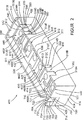
2 ist eine perspektivische Draufsicht auf das Empfangs- oder High-Band-Filter oder -zweig des Duplexfilters der vorliegenden Erfindung. 2 Figure 12 is a top perspective view of the receive or high band filter or leg of the duplex filter of the present invention.
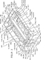
3 ist eine perspektivische Draufsicht einer Ausführungsform des Duplexfilters gemäß der vorliegenden Erfindung, die aus den Filtern von 1 und 2, die miteinander verbunden sind, gebildet ist. 3 FIG. 12 is a top perspective view of one embodiment of the duplex filter according to the present invention, which is made from the filters of FIG 1 and 2 which are interconnected.
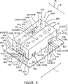
4 ist eine perspektivische Draufsicht des Duplexfilters von 3, das mit dem Hohlraum/Oberseite nach unten auf der Platine eines Kunden montiert ist; und 4 is a perspective top view of the duplex filter of 3 which is mounted with the cavity / topside down on a customer's board; and
5 ist eine grafische Darstellung der Signalstärke (oder des -verlustes) als Funktion der Frequenz für das Duplexfilter der vorliegenden Erfindung, das in den 3 und 4 gezeigt ist. 5 FIG. 4 is a graphical representation of the signal strength (or loss) as a function of frequency for the duplex filter of the present invention incorporated in the 3 and 4 is shown.
AUSFÜHRLICHE BESCHREIBUNG DER AUSFÜHRUNGSFORM DETAILED DESCRIPTION OF THE EMBODIMENT
Obwohl diese Erfindung für die Realisierung in vielen verschiedenen Formen geeignet ist, offenbaren diese Spezifikation und die begleitenden Zeichnungen eine Ausführungsform des Duplexfilters gemäß der vorliegenden Erfindung. Jedoch soll die Erfindung natürlich nicht auf die so beschriebene Ausführungsform beschränkt sein. Der Anwendungsbereich der Erfindung wird in den angehängten Ansprüchen angegeben.Although this invention is suitable for implementation in many different forms, this specification and the accompanying drawings disclose an embodiment of the duplex filter according to the present invention. However, the invention should of course not be limited to the embodiment thus described. The scope of the invention is indicated in the appended claims.
3 stellt eine Ausführungsform eines Duplexfilters 800 gemäß der vorliegenden Erfindung dar, das aus einem Sende- oder Low-Band-Simplexsignalfilter oder Zweig 10 (1) und einem Empfangs- oder High-Band-Simplexsignalfilter oder -zweig 400 (2) besteht, die in geeigneter Weise miteinander Seite an Seite verbunden sind, wie detaillierter unten erläutert wird. 3 represents an embodiment of a duplex filter 800 according to the present invention, consisting of a transmit or low band simplex signal filter or branch 10 ( 1 ) and a receive or high band simplex signal filter or branch 400 ( 2 ), which are suitably connected side by side, as explained in more detail below.
Mit Bezug auf 1 umfasst das Sendefilter 10 des Duplexfilters 800 einen im Allgemeinen länglichen Parallelepipedförmigen oder kastenförmigen starren Block oder Kern 12, der aus einem keramischen dielektrischen Material besteht, das eine gewünschte dielektrische Konstante hat. In einer Ausführugsform kann das dielektrische Material eine Barium- oder Neodymkeramik mit einer dielektrischen Konstante von etwa 37 oder darüber sein.Regarding 1 includes the transmission filter 10 of the duplex filter 800 a generally elongate parallelepiped or box-shaped rigid block or core 12 which is made of a ceramic dielectric material having a desired dielectric constant. In one embodiment, the dielectric material may be a barium or neodymium ceramic having a dielectric constant of about 37 or above.
Der Kern 12 definiert eine Außenfläche mit sechs mm Allgemeinen rechteckigen Seiten oder Flächen: eine obere Längsfläche 14; eine untere Längsfläche 16 (4), die parallel zur oberen Fläche 14 und diametral entgegengesetzt zu derselben ist; eine erste Längsseitenfläche 18; eine zweite Längsseitenfläche 20 (4), die parallel zur ersten Längsseitenfläche 18 und diametral entgegengesetzt zu derselben ist; eine dritte Querseiten- oder Stirnfläche 22; und eine vierte Querseiten- oder Stirnfläche 24, die parallel zur dritten Querseiten- oder Stirnfläche 22 und diametral entgegengesetzt zu derselben ist.The core 12 defines an outer surface with six mm of generally rectangular sides or surfaces: an upper longitudinal surface 14 ; a lower longitudinal surface 16 ( 4 ), which are parallel to the upper surface 14 and diametrically opposed to it; a first longitudinal side surface 18 ; a second longitudinal side surface 20 ( 4 ) parallel to the first longitudinal side surface 18 and diametrically opposed to it; a third transverse side or end face 22 ; and a fourth transverse side or end face 24 parallel to the third lateral or end face 22 and diametrically opposed to it.
Der Kern 12 definiert außerdem vier im Allgemeinen ebene Wände 110, 120, 130 und 140, die sich nach oben und außen weg von den jeweiligen vier äußeren Randkanten der oberen Fläche 14 erstrecken. Die Wände 110, 120, 130, 140 definieren zusammen einen oberen peripheren Filterrand 200, und die Wände 110, 120, 130, 140 und die obere Fläche 14 definieren zusammen einen Hohlraum 150 im oberen Teil des Filters 10.The core 12 also defines four generally flat walls 110 . 120 . 130 and 140 extending up and out away from the respective four outer marginal edges of the upper surface 14 extend. The walls 110 . 120 . 130 . 140 together define an upper peripheral filter rim 200 , and the walls 110 . 120 . 130 . 140 and the upper surface 14 define a cavity together 150 in the upper part of the filter 10 ,
Die sich längs erstreckenden Wände 110 und 120 sind parallel und diametral entgegengesetzt zueinander. Die sich quer erstreckenden Wände 130 und 140 sind parallel und diametral entgegengesetzt zueinander und sind mit den Wänden 110 und 120 verbunden und im Allgemeinen senkrecht zu denselben.The longitudinally extending walls 110 and 120 are parallel and diametrically opposed to each other. The transversely extending walls 130 and 140 are parallel and diametrically opposed to each other and are with the walls 110 and 120 connected and generally perpendicular to the same.
Die Wand 110 hat eine Außenfläche 111 (4) und eine Innenfläche 112. Die Außenfläche 111 hat dieselbe Ausdehnung wie die Seitenfläche 20 (4) und ist koplanar zu dieser. Ein zentraler Teil 110C der Wand 110 umfasst eine Innenfläche 112C, die sich vom Rand 200 weg neigt oder nach außen und unten in die obere Fläche 14 in Richtung der entgegengesetzten Wand 120 unter einem Winkel von ungefähr 45 Grad gegenüber der oberen Fläche 14 und der Wand 110 abknickt. Die Wände 120, 130 und 140 definieren alle im Allgemeinen senkrechte Außenwände, die im Allgemeinen koplanar zu den jeweiligen Kernseitenflächen und den im Allgemeinen vertikalen Innenwänden sind, die im Allgemeinen im Wesentlichen in einer Beziehung stehen, die zur horizontalen Ebene senkrecht ist, welche durch die obere Fläche 14 definiert wird.The wall 110 has an outer surface 111 ( 4 ) and an inner surface 112 , The outer surface 111 has the same extent as the side surface 20 ( 4 ) and is coplanar with this. A central part 110C the Wall 110 includes an inner surface 112C that are from the edge 200 Tilt away or out and down into the top surface 14 towards the opposite wall 120 at an angle of about 45 degrees to the top surface 14 and the wall 110 bends. The walls 120 . 130 and 140 all define generally vertical outer walls, which are generally coplanar with the respective core side surfaces and the generally vertical inner walls, which are generally substantially in a relationship perpendicular to the horizontal plane passing through the upper surface 14 is defined.
Die Wand 110 definiert außerdem mehrere im Allgemeinen parallele und mit Abstand angeordnete Wandteile. Ein Endwandteil 110A wird als benachbart und senkrecht zur Wand 130 definiert. Ein sich nach oben erstreckender isolierter Grundwandteil oder Ständer oder Finger 110B ist als benachbart und mit Abstand vom Wandteil 100A definiert Ein Schlitz 160 ist zwischen dem Endwandteil 110A und dem Ständer 110B definiert. Ein zentraler Wandteil 110C befindet sich neben dem Ständer 110B, ist aber mit Abstand zu demselben angeordnet. Ein Schlitz 162 ist zwischen dem Ständer 110B und dem zentralen Wandteil 110C definiert. Ein sich nach oben erstreckender isolierter Wandteil oder Ständer oder Finger 110D befindet sich neben dem zentralen Wandteil 110C, ist aber mit Abstand von demselben angeordnet. Ein Schlitz 164 ist zwischen dem zentralen Wandteil 110A und dem Ständer 110B definiert. Der Ständer 110D liegt diametral entgegengesetzt zu Ständer 110B und ist in einem Endteil der Wand 110 neben der Wand 140 definiert. Ein Endwandteil 110E ist zwischen der Wand 140 und dem Ständer 110D definiert. Das Wandteil 110E ist senkrecht zu Wand 140. Ein Schlitz 166 ist zwischen dem Ständer 110D und dem Wandteil 110E definiert.The wall 110 also defines a plurality of generally parallel and spaced wall portions. An end wall part 110A is considered adjacent and perpendicular to the wall 130 Are defined. An upwardly extending insulated base wall part or stand or finger 110B is as adjacent and at a distance from the wall part 100A defines a slot 160 is between the end wall part 110A and the stand 110B Are defined. A central wall part 110C is located next to the stand 110B but is at a distance from it. A slot 162 is between the stand 110B and the central wall part 110C Are defined. An upwardly extending insulated wall part or stand or finger 110D is located next to the central wall part 110C but is at a distance from it. A slot 164 is between the central wall part 110A and the stand 110B Are defined. The stand 110D is diametrically opposed to stands 110B and is in an end part of the wall 110 beside the wall 140 Are defined. An end wall part 110E is between the wall 140 and the stand 110D Are defined. The wall part 110E is perpendicular to wall 140 , A slot 166 is between the stand 110D and the wall part 110E Are defined.
Die Innenfläche 112 der Wand 110 ist ferner in mehrere Abschnitte getrennt, die die vertikalen Innenteile 112A und 112B und die abgewinkelten oder geneigten Flächenteile 112C, 112D und 112E umfassen. Der Innenflächenteil 112A befindet sich auf den Wandteil 110A. Der Innenflächenteil 112B befindet sich auf dem Wandteil oder Ständer 110B. Der Innenflächenteil 112C befindet sich auf dem Wandteil 110C. Der Innenflächenteil 112D befindet sich auf dem Wandteil oder Ständer 110D. Der Innenflächenteil 112E befindet sich auf dem Wandteil 110E.The inner surface 112 the Wall 110 is further divided into several sections, which are the vertical inner parts 112A and 112B and the angled or inclined surface parts 112C . 112D and 112E include. The inner surface part 112A is located on the wall part 110A , The inner surface part 112B is located on the wall part or stand 110B , The inner surface part 112C is located on the wall part 110C , Of the Inner surface portion 112D is located on the wall part or stand 110D , The inner surface part 112E is located on the wall part 110E ,
Die Wandteile 110C, 110D und 110E definieren ferner die im Allgemeinen dreieckig geformten Seitenwände. Speziell definiert Wandteil 110C eine Seitenwand 114D, die mit Abstand von Ständer 110B angeordnet ist, und eine gegenüberliegende Seitenwand 114E, welche mit Abstand von Ständer 110D angeordnet ist. Der Ständer 110D definiert eine Seitenwand 114F, die mit Abstand von Wandteil 110C angeordnet ist, und eine Seitenwand 114G, die mit Abstand von Wandteil 110E angeordnet ist. Der Wandteil 110E definiert eine Seitenwand 114H, die mit Abstand von Ständer 110D angeordnet ist.The wall parts 110C . 110D and 110E further define the generally triangular shaped sidewalls. Specially defined wall part 110C a side wall 114D by far from stands 110B is arranged, and an opposite side wall 114E , which by far from the stand 110D is arranged. The stand 110D defines a sidewall 114F , by far from wall part 110C is arranged, and a side wall 114G , by far from wall part 110E is arranged. The wall part 110E defines a sidewall 114H by far from stands 110D is arranged.
Die Wand 120 hat eine Außenfläche 121 und eine Innenfläche (nicht dargestellt). Die Außenfläche 121 hat dieselbe Ausdehnung und ist koplanar zur Kernseitenfläche 18, und die Innenfläche (nicht dargestellt) ist senkrecht zur oberen Kernfläche 14.The wall 120 has an outer surface 121 and an inner surface (not shown). The outer surface 121 has the same extent and is coplanar with the core side surface 18 , and the inner surface (not shown) is perpendicular to the upper core surface 14 ,
Die Wand 130 hat eine Außenfläche 131 und eine Innenfläche (nicht dargestellt). Die Außenfläche 131 hat dieselbe Ausdehnung und ist koplanar zur Kernseitenfläche 24, und die Innenfläche (nicht dargestellt) ist senkrecht zur oberen Kernfläche 14.The wall 130 has an outer surface 131 and an inner surface (not shown). The outer surface 131 has the same extent and is coplanar with the core side surface 24 , and the inner surface (not shown) is perpendicular to the upper core surface 14 ,
Die Wand 140 hat eine Außenfläche (nicht dargestellt) und eine Innenfläche 142. Die Außenfläche (nicht dargestellt) hat dieselbe Ausdehnung und ist koplanar zur Kernseitenfläche 22, und die Innenfläche 142 ist senkrecht zur oberen Kernfläche 14.The wall 140 has an outer surface (not shown) and an inner surface 142 , The outer surface (not shown) has the same extent and is coplanar with the core side surface 22 , and the inner surface 142 is perpendicular to the upper core surface 14 ,
Ein sich nach oben erstreckender isolierter Wandteil oder Ständer oder Finger 300 ist in einer linken unteren Ecke des Kerns 12 definiert, der die Kernseitenflächen 18 und 24 überbrückt. Der Ständer 300 ist mit Abstand zu den Wänden 120 und 130 angeordnet, um so einen Schlitz 302 zwischen dem Ständer 300 und der Wand 130 und einen Schlitz 304 zwischen dem Ständer 300 und der Wand 120 zu definieren. Der Ständer 300 definiert ein Paar von im Allgemeinen dreieckig geformten Seitenwänden 308, welche nicht mit Metallbeschichtung versehen sind und an die nicht-metallisierte Fläche 44 grenzen, wie detaillierter unten beschrieben wird. Die äußere Seitenwand 308 ist koplanar zur Seitenkernfläche 18 und zur Außenfläche 121 der Wand 120. Der Ständer 300 hat einen metallisierten oberen Rand 312, eine metallisierte Vorderfläche 306, die koplanar zur Kernstirnfläche 24 und der Außenfläche 131 der Wand 130 ist, und eine metallisierte innere abgewinkelte oder geneigte Fläche 310.An upwardly extending insulated wall part or stand or finger 300 is in a lower left corner of the core 12 defines the core side surfaces 18 and 24 bridged. The stand 300 is at a distance to the walls 120 and 130 arranged so as to have a slot 302 between the stand 300 and the wall 130 and a slot 304 between the stand 300 and the wall 120 define. The stand 300 defines a pair of generally triangular shaped sidewalls 308 , which are not provided with metal coating and to the non-metallized surface 44 limits, as described in more detail below. The outer side wall 308 is coplanar to the side core surface 18 and the outside surface 121 the Wall 120 , The stand 300 has a metallized upper edge 312 , a metallized front surface 306 , coplanar to the core end face 24 and the outer surface 131 the Wall 130 is, and a metallized inner angled or inclined surface 310 ,
Das Simplex-Sendesignalfilter 10 umfasst zusätzlich mehrere Resonatoren 25, die teilweise durch mehrere metallisierte Durchgangslöcher 30 definiert sind, welche im dielektrischen Kern 12 definiert sind und in entsprechenden Öffnungen in der Ober- und Unterseite 14 (1) und 16 (4) des Kerns 12 enden. Die Durchgangslöcher 30 erstrecken sich entlang der Länge des Blocks 12 von einem Punkt, der neben der Kernseitenfläche 22 liegt, bis zu einem Punkt, der neben der gegenüberliegenden Kernseitenfläche 24 liegt, mit Abstand in kollinearer Anordnung. Jedes der Durchgangslöcher 30 ist durch eine innere zylindrische metallisierte Seitenwandfläche 32 definiert.The simplex transmit signal filter 10 additionally includes several resonators 25 partially through multiple metallized through holes 30 which are defined in the dielectric core 12 are defined and in corresponding openings in the top and bottom 14 ( 1 ) and 16 ( 4 ) of the core 12 end up. The through holes 30 extend along the length of the block 12 from a point next to the core side surface 22 lies, to a point, in addition to the opposite core side surface 24 is located, by far in a collinear arrangement. Each of the through holes 30 is through an inner cylindrical metallized side wall surface 32 Are defined.
Die Oberseite 14 des Kerns 12 definiert außerdem ein vertieftes Oberflächenschichtmuster 40 der entsprechenden elektrisch leitfähigen metallisierten und isolierenden nicht metallisierten Flächen oder Muster. Ein Teil des Musters 40 ist auf der Oberseite 14 des Kerns 12 definiert und definiert daher ein Vertiefungsfiltermuster dank seiner vertieften Lage an der Basis von Hohlraum 150 mit Abstand zu dem oberen Rand 200 der Kernwände 110, 120, 130 und 140.The top 14 of the core 12 also defines a recessed surface layer pattern 40 the corresponding electrically conductive metallized and insulating non-metallized areas or patterns. Part of the pattern 40 is on the top 14 of the core 12 therefore defines and defines a pit filter pattern thanks to its recessed location at the base of the cavity 150 at a distance from the upper edge 200 the core walls 110 . 120 . 130 and 140 ,
Die metallisierten Bereiche können eine Oberflächenschicht aus leitfähigem silberhaltigem Material sein. Das vertiefte Muster 40 definiert auch einen breiten Bereich oder Muster von Metallbeschichtung, der die Kernunterseite 16, alle Kernseitenflächen und die Seitenwand 32 der entsprechenden Durchgangslöcher 30 bedeckt und sich zusammenhängend von der Innenseite der Resonatordurchgangslöcher 30 zur Kernoberseite 14 und Kernunterseite 16 hin erstreckt und auch als Masseelektrode bezeichnet werden kann, die zum Absorbieren oder Verhindern der Übertragung von außerhalb des Bandes auftretenden Signalen dient.The metallized regions may be a surface layer of conductive silver-containing material. The deepened pattern 40 Also defines a wide area or pattern of metal coating, which is the core base 16 , all core side surfaces and the side wall 32 the corresponding through holes 30 covered and contiguous from the inside of the resonator vias 30 to the core top 14 and core base 16 and also referred to as a ground electrode, which serves to absorb or prevent the transmission of out-of-band signals.
Das vertiefte Muster 40 auf der Kernoberfläche 14 umfasst zumindest die Resonatoranschlussflächen 60A, 60B, 60C, 60D, 60E und 60F, die zumindest teilweise die oberen Öffnungen der jeweiligen Durchgangslöcher 30 umgeben. Die Resonatoranschlussflächen 60A–F sind zusammenhängend oder mit dem Metallisierungsbereich verbunden, der sich durch die jeweiligen Innenflächen 32 der Durchgangslöcher 30 erstreckt und so geformt ist, dass er vorgegebene kapazitive Kopplungen zu benachbarten Resonatoren und anderen Bereichen der Oberflächenschicht-Metallisierung aufweist.The deepened pattern 40 on the core surface 14 includes at least the resonator pads 60A . 60B . 60C . 60D . 60E and 60F at least partially the upper openings of the respective through holes 30 surround. The resonator pads 60A -F are connected or connected to the metallization area extending through the respective inner surfaces 32 the through holes 30 and is shaped to have predetermined capacitive couplings to adjacent resonators and other areas of the surface layer metallization.
Ein nicht metallisierter Bereich oder Muster 44 umgibt alle metallisierten Resonatoranschlussflächen 60A–F, erstreckt sich zumindest über Teile der Kernseitenflächen 18, 20 und 24, bis zu den Schlitzteilen 182, 183, 320 und 322 der Kernoberseite und bis zu den Kernseitenwandteilen 114E, 114F, 114G, 114H und der äußeren Seitenwand 308 des Ständers 300. An unmetallized area or pattern 44 surrounds all metalized resonator pads 60A -F, extends at least over parts of the core side surfaces 18 . 20 and 24 , up to the slot parts 182 . 183 . 320 and 322 the core top and up to the core sidewall parts 114E . 114F . 114G . 114H and the outer sidewall 308 of the stand 300 ,
Der nicht metallisierte Bereich 44 definiert auch einen im Allgemeinen rechteckig geformten nicht metallisierten Bereich 314, der sich bis zu einem Teil der Kernseitenfläche 24 erstreckt, welcher sich unter der Vorderseite 306 des Ständers 300 und dem Schlitz 302 befindet. Ein anderer im Allgemeinen rechteckig geformter nicht metallisierter Bereich 316 ist mit dem Bereich 314 verbunden und erstreckt sich bis zu einem Teil der Kernseitenfläche 18, der sich unter der äußeren Seitenwand 308 des Ständers 300 und dem Schlitz 304 befindet.The non-metallized area 44 also defines a generally rectangular shaped non-metallized region 314 that extends to part of the core side surface 24 which extends below the front 306 of the stand 300 and the slot 302 located. Another generally rectangular shaped non-metallized area 316 is with the area 314 connected and extends to a part of the core side surface 18 that is under the outer sidewall 308 of the stand 300 and the slot 304 located.
Ein ähnlicher, im Allgemeinen rechteckig geformter nicht metallisierter Bereich 317 (4) erstreckt sich bis zu einem Teil der Kernseitenfläche 20, die sich oberhalb des Ständer 110D und der Schlitze 164 und 166 befindet.A similar, generally rectangular shaped, non-metallized region 317 ( 4 ) extends to a part of the core side surface 20 that are above the stand 110D and the slots 164 and 166 located.
Das Oberflächenschichtmuster 40 auf der Kernoberseite 14 definiert zusätzlich ein Paar von isolierten leitfähigen metallisierten Signalbereichen: einen Sende-Ein-/Ausgangssignal-Anschlussbereich oder -elektrode 210; und eine Antennen-Ein-/Ausgangssignal-Anschlussbereich oder -elektrode 330.The surface layer pattern 40 on the core top 14 additionally defines a pair of isolated conductive metalized signal areas: a transmit input / output port area or electrode 210 ; and an antenna input / output port area or electrode 330 ,
Der Ein-/Ausgangssignal-Anschlussbereich 210 erstreckt sich bis auf einen Teil der Wand 110 und, spezieller, auf die Innenflächen- und oberen Randteile 112 und 200 des HF-Signaleingangs/-ausgangsständers 110D, um zum Beispiel einen leitfähigen Oberflächenmontage-Sendesignal-Anschlusspunkt oder -Anschlussfläche oder Kontakt zu definieren, wie detaillierter unten beschrieben wird.The input / output connection area 210 extends to a part of the wall 110 and, more particularly, to the inner surface and upper edge portions 112 and 200 of the RF signal input / output stand 110D to define, for example, a conductive surface mount transmit signal terminal or pad, or contact, as described in greater detail below.
Der Anschlussbereich der Metallbeschichtung oder Elektrode 210 befindet sich neben Wand 140. Der Eingangsanschlussbereich oder die Elektrode 210 umfasst die Elektrodenteile 211, 212, 213 und 214. Der Elektrodenteil 211 befindet sich zwischen den Resonatoranschlussflächen 60E und 60F und ist mit dem Elektrodenteil 212 verbunden, der sich auf dem Innenflächenteil 112D von Ständer 110D befindet. Der Elektrodenteil 213 ist mit den Elektrodenteilen 211 und 212 verbunden. Der Elektrodenteil 214 befindet sich auf dem oberen Randteil 200 des Ständers 110D. Der Elektrodenteil 214 ist mit dem Elektrodenteil (nicht dargestellt) verbunden, der sich auf der Außenfläche des Ständers 110D befindet. Der Elektrodenteil 214 ist auf allen Seiten von nicht metallisierten Flächen umgeben.The connection area of the metal coating or electrode 210 is located next to wall 140 , The input terminal area or the electrode 210 includes the electrode parts 211 . 212 . 213 and 214 , The electrode part 211 is located between the resonator pads 60E and 60F and is with the electrode part 212 connected, located on the inner surface part 112D from stand 110D located. The electrode part 213 is with the electrode parts 211 and 212 connected. The electrode part 214 is located on the upper edge part 200 of the stand 110D , The electrode part 214 is connected to the electrode part (not shown) located on the outer surface of the stator 110D located. The electrode part 214 is surrounded on all sides by non-metallised surfaces.
Der Antennenanschlussbereich 330 erstreckt sich bis auf den Ständer 300, wo er als leitfähiger Anschlusspunkt oder Anschlussfläche oder Kontakt oder Ständer zur Oberflächenmontage der Antenne dient, wie detaillierter unten beschrieben.The antenna connection area 330 extends to the stand 300 where it serves as a conductive terminal or pad, or contact or stand for surface mounting the antenna, as described in more detail below.
Der Antennenanschlussbereich der Metallisierung oder Elektrode 330 ist im Allgemeinen L-förmig und befindet sich neben der Wand 120. Die Elektrode 330 umfasst die Elektrodenteile 331, 332, 333, 334 und 335. Der Elektrodenteil 332 befindet sich zwischen den Resonatoranschlussflächen 60A und 60B und ist mit dem Elektrodenteil 331 verbunden. Der Elektrodenteil 333 befindet sich auf dem Innenflächenteil 310 des Ständers 300 und ist mit dem Elektrodenteil 331 verbunden. Der Elektrodenteil 334 befindet sich auf dem oberen Randteil 200 von Ständer 300 und ist mit dem Elektrodenteil 333 verbunden. Der Elektrodenteil 335 befindet sich auf der Außenfläche 306 des Ständers 300 und ist auf allen Seiten von nicht metallisierten Bereichen umgeben.The antenna connection area of the metallization or electrode 330 is generally L-shaped and located next to the wall 120 , The electrode 330 includes the electrode parts 331 . 332 . 333 . 334 and 335 , The electrode part 332 is located between the resonator pads 60A and 60B and is with the electrode part 331 connected. The electrode part 333 is located on the inner surface part 310 of the stand 300 and is with the electrode part 331 connected. The electrode part 334 is located on the upper edge part 200 from stand 300 and is with the electrode part 333 connected. The electrode part 335 located on the outside surface 306 of the stand 300 and is surrounded on all sides by non-metallized areas.
Das vertiefte Oberflächenmuster 40 umfasst metallisierte Bereiche und nicht metallisierte Bereiche. Die metallisierten Bereiche sind mit Abstand zueinander angeordnet und sind daher kapazitiv gekoppelt. Die Stärke der kapazitiven Kopplung steht in ungefährer Beziehung zur Größe der Metallisierungsbereiche und dem Trennabstand zwischen benachbarten metallisierten Abschnitte sowie der gesamten Kernkonfiguration und der dielektrischen Konstante des dielektrischen Kernmaterials. Ähnlich erzeugt das Oberflächenmuster 40 auch eine induktive Kopplung zwischen den metallisierten Bereichen.The recessed surface pattern 40 includes metallized areas and non-metallized areas. The metallized regions are arranged at a distance from one another and are therefore capacitively coupled. The magnitude of the capacitive coupling is approximately related to the size of the metallization regions and the separation distance between adjacent metallized portions as well as the overall core configuration and the dielectric constant of the dielectric core material. The surface pattern produces similar 40 also an inductive coupling between the metallized areas.
Wendet man sich nun 2 zu, so umfasst das Empfangsignalfilter 400 einen im Allgemeinen länglichen, Parallelepiped-förmigen oder kastenförmigen starren Block oder Kern 412, der aus einem keramischen dielektrischen Material besteht, das eine gewünschte dielektrische Konstante hat. In einer Ausführungsform kann das dielektrische Material eine Barium- oder Neodymkeramik mit einer dielektrischen Konstante von etwa 37 oder darüber sein.Turning now 2 to, so includes the receive signal filter 400 a generally elongated, parallelepiped-shaped or box-shaped rigid block or core 412 which is made of a ceramic dielectric material having a desired dielectric constant. In one embodiment, the dielectric material may be a barium or neodymium ceramic having a dielectric constant of about 37 or above.
Der Kern 412 definiert eine Außenfläche mit sechs im Allgemeinen rechteckigen Seiten: eine obere Kernlängsfläche 414; eine untere Kernlängsfläche 416 (4), die parallel zur Kernoberfläche 414 und diametral entgegengesetzt zu derselben ist; eine erste Kernlängsseitenfläche 418; eine zweite Kernlängsseitenfläche 420, die parallel zur Seitenfläche 418 und diametral entgegengesetzt zu derselben ist; eine dritte Kernquerseiten- oder Stirnfläche 424; und eine vierte Kernquerseiten- oder Stirnfläche 422, die parallel zur Kernstirnfläche 424 und diametral entgegengesetzt zu derselben ist. The core 412 defines an outer surface with six generally rectangular sides: an upper core longitudinal surface 414 ; a lower core longitudinal surface 416 ( 4 ), which are parallel to the core surface 414 and diametrically opposed to it; a first core side surface 418 ; a second core side surface 420 parallel to the side surface 418 and diametrically opposed to it; a third core transverse side or end face 424 ; and a fourth core transverse side or end surface 422 parallel to the core end face 424 and diametrically opposed to it.
Der Kern 412 definiert außerdem vier im Allgemeinen ebene Wände 510, 520, 530 und 540, die sich nach oben und außen weg von den jeweiligen vier äußeren Randkanten der Kernoberfläche 414 erstrecken. Die Wände 510, 520, 530 und 540 definieren zusammen einen oberen Umfangsrand 600, und die Wände 510, 520, 530, 540 und die obere Fläche 414 werden miteinander kombiniert, um einen Hohlraum 550 an der Oberseite des Filters 400 zu definieren. Sich längs erstreckende Wände 510 und 520 sind parallel und diametral entgegengesetzt zueinander. Sich quer erstreckende Wände 530 und 540 sind parallel und diametral entgegengesetzt zueinander und sind mit den Wänden 510 und 520 verbunden und im Allgemeinen senkrecht zu denselben.The core 412 also defines four generally flat walls 510 . 520 . 530 and 540 extending up and out away from the respective four outer marginal edges of the core surface 414 extend. The walls 510 . 520 . 530 and 540 together define an upper peripheral edge 600 , and the walls 510 . 520 . 530 . 540 and the upper surface 414 are combined together to form a cavity 550 at the top of the filter 400 define. Lengthwise extending walls 510 and 520 are parallel and diametrically opposed to each other. Transverse walls 530 and 540 are parallel and diametrically opposed to each other and are with the walls 510 and 520 connected and generally perpendicular to the same.
Die Wand 510 hat eine Außenfläche 511 und eine Innenfläche 512. Die Außenfläche 511 hat dieselbe Ausdehnung und ist koplanar zur Kernseitenfläche 418, während ein Teil der Innenfläche 512 sich vom Rand 600 weg neigt oder nach außen und unten in die Kernoberfläche 414 in Richtung der gegenüberliegenden Wand 520 unter ca. 45 Grad gegenüber der Kernoberfläche 414 und der Wand 510 abgewinkelt ist. Die Wände 520, 530 und 540 definieren alle im Allgemeinen senkrechte Außenwände, die im Allgemeinen koplanar zu den jeweiligen Kernseitenflächen 420, 424 und 422 und den im Allgemeinen vertikalen Innenwänden sind, die im Allgemeinen im Wesentlichen in einer Beziehung stehen, die zur horizontalen Ebene senkrecht ist, welche durch die Kernoberfläche 414 definiert wird.The wall 510 has an outer surface 511 and an inner surface 512 , The outer surface 511 has the same extent and is coplanar with the core side surface 418 while part of the inner surface 512 away from the edge 600 tending away or out and down into the core surface 414 towards the opposite wall 520 below about 45 degrees from the core surface 414 and the wall 510 is angled. The walls 520 . 530 and 540 all define generally vertical outer walls that are generally coplanar with the respective core side surfaces 420 . 424 and 422 and the generally vertical inner walls, which are generally substantially in a relationship perpendicular to the horizontal plane passing through the core surface 414 is defined.
Die Wand 510 definiert außerdem mehrere im Allgemeinen parallele und mit Abstand angeordnete Schlitze 560, 562, 564 und 566.The wall 510 also defines a plurality of generally parallel and spaced slots 560 . 562 . 564 and 566 ,
Ein Endwandteil 510A ist zwischen der Wand 530 und dem Schlitz 560 definiert. Der Endwandteil 510A ist senkrecht zu Wand 530. Ein isolierter Grundwandteil oder Ständer oder Finger 510B befindet sich neben dem Wandabschnitt 510A, ist aber mit Abstand von demselben angeordnet, und der Raum dazwischen definiert den Schlitz 560. Ein Mittelwandteil 510C befindet sich neben, aber mit Abstand von Ständer 510B, und der Raum dazwischen definiert den Schlitz 562. Ein isolierter Wandteil oder Ständer oder Finger 510D befindet sich neben dem Mittelwandteil 510, ist aber mit Abstand von demselben angeordnet, und der Raum dazwischen definiert den Schlitz 564. Der Ständer 510D ist diametral dem Ständer 510B entgegengesetzt. Ein Mittelwandteil 510E befindet sich neben dem Ständer 510B, ist aber mit Abstand von demselben angeordnet, und der Raum dazwischen definiert den Schlitz 566. Die Ständer 510B und 510D erstrecken sich im Allgemeinen senkrecht nach außen und oben weg von der Kernoberfläche 414 des Filters 400.An end wall part 510A is between the wall 530 and the slot 560 Are defined. The end wall part 510A is perpendicular to wall 530 , An isolated base part or stand or finger 510B is located next to the wall section 510A but is spaced therefrom and the space between defines the slot 560 , A middle wall part 510C is next to, but at a distance from, the stand 510B and the space in between defines the slot 562 , An isolated wall part or stand or finger 510D is located next to the middle wall part 510 but is spaced therefrom and the space between defines the slot 564 , The stand 510D is diametrically the stand 510B opposed. A middle wall part 510E is located next to the stand 510B but is spaced therefrom and the space between defines the slot 566 , The stands 510B and 510D generally extend perpendicularly outwardly and upwardly away from the core surface 414 of the filter 400 ,
Die Innenfläche ausgewählter Abschnitte der Wand 510 ist abgewinkelt oder geneigt. Ein innerer abgewinkelter Flächenteil 512C befindet sich auf dem Wandteil 510C. Ein innerer abgewinkelter Flächenteil 512D befindet sich auf denn Wandteil oder Ständer 510D. Ein innerer abgewinkelter Flächenteil 512E befindet sich auf dem Wandteil 510E.The inner surface of selected sections of the wall 510 is angled or tilted. An inner angled surface part 512C is located on the wall part 510C , An inner angled surface part 512D is on the wall part or stand 510D , An inner angled surface part 512E is located on the wall part 510E ,
Die Wandteile 510C, 510D und 510E definieren ferner die im Allgemeinen dreieckig geformten Seitenwände. Speziell definiert der Wandteil 510C eine Seitenwand 514D, die dem Ständer 510B benachbart ist, und eine gegenüberliegende Seitenwand (nicht dargestellt), die dem Ständer 510D benachbart ist. Der Ständer 510D definiert eine Seitenwand 514F, die dem Wandteil 510C benachbart ist, und eine Seitenwand 514G, die dem Stirnwandteil 510E benachbart ist. Der Wandteil 510E definiert eine Seitenwand 514H, die dem Ständer 510D benachbart ist.The wall parts 510C . 510D and 510E further define the generally triangular shaped sidewalls. Specially defined the wall part 510C a side wall 514D that the stand 510B is adjacent, and an opposite side wall (not shown), which the stand 510D is adjacent. The stand 510D defines a sidewall 514f that the wall part 510C is adjacent, and a side wall 514G that the front wall part 510E is adjacent. The wall part 510E defines a sidewall 514H that the stand 510D is adjacent.
Die Wand 520 hat eine Außenfläche (nicht dargestellt) und eine Innenfläche 522. Die Außenfläche (nicht dargestellt) bat dieselbe Ausdehnung und ist koplanar zur Kernseitenfläche 420, und die Innenfläche 522 ist senkrecht zur Kernoberfläche 414.The wall 520 has an outer surface (not shown) and an inner surface 522 , The outer surface (not shown) has the same extension and is coplanar with the core side surface 420 , and the inner surface 522 is perpendicular to the core surface 414 ,
Die Wand 530 hat eine Außenfläche 531 und eine Innenfläche (nicht dargestellt). Die Außenfläche 531 hat dieselbe Ausdehnung und ist koplanar zur Kernseitenfläche 424, und die Innenfläche (nicht dargestellt) ist senkrecht zur Kernoberfläche 414.The wall 530 has an outer surface 531 and an inner surface (not shown). The outer surface 531 has the same extent and is coplanar with the core side surface 424 , and the inner surface (not shown) is perpendicular to the core surface 414 ,
Die Wand 540 hat eine Außenfläche (nicht dargestellt) und eine Innenfläche 542. Die Außenfläche (nicht dargestellt) hat dieselbe Ausdehnung und ist koplanar zur Kernseitenfläche 422, und die Innenfläche 542 ist senkrecht zur Kernoberfläche 414. The wall 540 has an outer surface (not shown) and an inner surface 542 , The outer surface (not shown) has the same extent and is coplanar with the core side surface 422 , and the inner surface 542 is perpendicular to the core surface 414 ,
Ein isolierter Wandteil oder Ständer oder Finger 700 ist in der linken oberen Ecke des Kerns 412 in der Nachbarschaft und mit Abstand von den jeweiligen Wänden 520 und 530 definiert. Der Raum zwischen Ständer 700 und Wand 530 definiert einen Schlitz 702. Der Raum zwischen dem Ständen 700 und der Wand 520 definiert einen Schlitz 704. Der Ständer 700 definiert ein Paar von im Allgemeinen dreieckig geformten Seitenwänden 709, die nicht mit metallisiert sind und an den nicht metallisierten Bereich 444 auf der Kernoberfläche 414 grenzen, wie detaillierter unten beschrieben wird. Der Ständer 700 hat einen metallisierten oberen Rand 712, eine metallisierte Vorderfläche 706, die koplanar zu der Kernseitenfläche 424 und der Außenfläche 531 der Wand 530 ist, und eine metallisierte innere abgewinkelte oder geneigte Fläche 710. Der Ständer 700 erstreckt sich normalerweise von der oberen Filterfläche 414 aus nach oben und außen. Die Außenwand 709 des Ständers 700 ist koplanar zur Kernseitenfläche 420 und der Außenfläche (nicht dargestellt) der Wand 520.An isolated wall part or stand or finger 700 is in the upper left corner of the core 412 in the neighborhood and at a distance from the respective walls 520 and 530 Are defined. The space between stand 700 and wall 530 defines a slot 702 , The space between the stalls 700 and the wall 520 defines a slot 704 , The stand 700 defines a pair of generally triangular shaped sidewalls 709 that are not metallized and attached to the non-metallized area 444 on the core surface 414 limits, as described in more detail below. The stand 700 has a metallized upper edge 712 , a metallized front surface 706 that coplanar to the core side surface 424 and the outer surface 531 the Wall 530 is, and a metallized inner angled or inclined surface 710 , The stand 700 normally extends from the upper filter surface 414 out up and out. The outer wall 709 of the stand 700 is coplanar to the core side surface 420 and the outer surface (not shown) of the wall 520 ,
Das Empfangsfilter 400 hat mehrere Resonatoren 425, die teilweise durch mehrere Durchgangslöcher 430 definiert sind, welche im dielektrischen Kern 412 definiert sind. Die Durchgangslöcher 430 erstrecken sich und enden in von jeweiligen Öffnungen, die in den oberen und der unteren Kernfläche 414 bzw. 416 definiert sind. Die Durchgangslöcher 430 erstrecken sich entlang der Längsachse von Block 412, angeordnet mit Abstand und in einer kollinearen Beziehung. Jedes der Durchgangslöcher 430 ist durch eine innere zylindrische metallisierte Seitenwandfläche 432 definiert.The receive filter 400 has several resonators 425 partially through multiple through holes 430 which are defined in the dielectric core 412 are defined. The through holes 430 extend and terminate in respective openings in the upper and lower core surfaces 414 respectively. 416 are defined. The through holes 430 extend along the longitudinal axis of block 412 arranged at a distance and in a collinear relationship. Each of the through holes 430 is through an inner cylindrical metallized side wall surface 432 Are defined.
Die obere Fläche 414 des Kerns 412 definiert außerdem ein vertieftes Oberflächenschichtmuster 440 der entsprechenden elektrisch leitfähigen metallisierten und isolierenden nicht metallisierten Bereiche oder Muster. Ein Teil des Musters 440 ist auf der oberen Fläche 414 des Kerns 412 definiert und definiert daher ein vertieftes Filtermuster dank seiner vertieften Lage an der Basis des Hohlraums 550 mit Abstand vom oberen Rand 600 der Wände 510, 520, 530 und 540.The upper surface 414 of the core 412 also defines a recessed surface layer pattern 440 the corresponding electrically conductive metallized and insulating non-metallized regions or patterns. Part of the pattern 440 is on the upper surface 414 of the core 412 defines and therefore defines a deepened filter pattern thanks to its recessed location at the base of the cavity 550 at a distance from the top 600 the walls 510 . 520 . 530 and 540 ,
Die metallisierten Bereiche können eine Oberflächenschicht aus leitfähigem silberhaltigem Material sein. Das vertiefte Muster 440 definiert auch einen breiten Bereich oder ein Muster oder einen Abschnitt der Metallisierung, der die Ober-, Unter- und Seitenkernflächen 414, 416, 418, 420, 422 und 424 und die Innenwände 432 der Durchgangslöcher 430 bedeckt und sich zusammenhängend vom Inneren der Resonatordurchgangslöcher 430 zur Oberseite 414 und der Unterseite 416 hin erstreckt und auch als Masseelektrode gekennzeichnet werden kann und zum Absorbieren oder Verhindern der Übertragung von außerhalb der Bänder liegenden Signalen dient.The metallized regions may be a surface layer of conductive silver-containing material. The deepened pattern 440 also defines a broad area or pattern or portion of the metallization that defines the top, bottom and side core surfaces 414 . 416 . 418 . 420 . 422 and 424 and the interior walls 432 the through holes 430 covered and contiguous from the interior of the resonator vias 430 to the top 414 and the bottom 416 extends and can also be characterized as a ground electrode and serves to absorb or prevent the transmission of out-of-band signals.
Das vertiefte Muster 440 auf der Kernoberseite 414 umfasst mehrere Resonatoranschlussflächen 460A, 460B, 460C, 460D, 460E und 460F, die zumindest teilweise die jeweiligen Öffnungen der Durchgangslöcher 430 umgeben, welche auf der Kernoberseite 414 definiert sind. Die Resonatoranschlussflächen 460A–F sind mit der Metallbeschichtung zusammenhängend oder verbunden, die sich durch die jeweiligen Innenflächen 432 der Durchgangslöcher 430 erstreckt und so geformt ist, dass sie vorgegebene kapazitive Kopplungen zu benachbarten Resonatoren und anderen Bereichen der Oberflächenschichtmetallisierung aufweist.The deepened pattern 440 on the core top 414 includes several resonator pads 460A . 460B . 460C . 460D . 460E and 460F at least partially the respective openings of the through holes 430 surrounded, which on the core top 414 are defined. The resonator pads 460A -F are contiguous or bonded to the metal coating extending through the respective inner surfaces 432 the through holes 430 and is shaped to have predetermined capacitive couplings to adjacent resonators and other areas of the surface layer metallization.
Ein nicht metallisierter Bereich oder Muster 444 erstreckt sich über Teile der Kernoberseite 414 und zumindest Teile der Kernseitenflächen 418, 420 und 424. Der nicht metallisierte Bereich 444 auf der Kernoberseite 414 umgibt alle metallisierten Resonatoranschlussflächen 460A–F.An unmetallized area or pattern 444 extends over parts of the core top 414 and at least parts of the core side surfaces 418 . 420 and 424 , The non-metallized area 444 on the core top 414 surrounds all metalized resonator pads 460A -F.
Der nicht metallisierte Bereich 444 erstreckt sich auch auf zumindest die Schlitzabschnitte 582, 583, 720 und 722 der Oberseite und die Seitenwandabschnitte 514E, 514F, 514G, 514H und 709 und bedeckt dieselben.The non-metallized area 444 also extends to at least the slot sections 582 . 583 . 720 and 722 the top and sidewall sections 514e . 514f . 514G . 514H and 709 and covers them.
Der nicht metallisierte Bereich 444 definiert auch einen im Allgemeinen rechteckig geformten nicht metallisierten Bereich 714, der sich bis zu einem Teil der Kernseitenfläche 424 erstreckt, welche sich unter der Vorderseite 706 des Ständers 700 und dem Schlitz 702 befindet. Ein anderer im Allgemeinen rechteckig geformten nicht metallisierter Bereich (nicht dargestellt) ist mit dem nicht metallisierten Bereich 714 verbunden und erstreckt sich auf einen Teil der Kernseitenfläche 420, die sich unterhalb der äußeren Seitenfläche 708 des Ständers 700 und des Schlitzes 704 befindet.The non-metallized area 444 also defines a generally rectangular shaped non-metallized region 714 that extends to part of the core side surface 424 which extends below the front 706 of the stand 700 and the slot 702 located. Another generally rectangular shaped non-metallized area (not shown) is with the non-metallized area 714 connected and extends to a part of the core side surface 420 extending below the outer side surface 708 of the stand 700 and the slot 704 located.
Ein ähnlicher, im Allgemeinen rechteckig geformter nicht metallisierter Bereich 448 erstreckt sich bis auf einen Teil der Kernseitenfläche 418, der sich unterhalb der Vorderseite des Ständers 510D und der Schlitze 564 und 566 befindet. A similar, generally rectangular shaped, non-metallized region 448 extends to a part of the core side surface 418 that extends below the front of the stand 510D and the slots 564 and 566 located.
Das Oberflächenschichtmuster 440 auf der Kernoberseite 414 definiert außerdem ein Paar von isolierten leitfähigen metallisierten Anschlussflächen, einschließlich einer Empfangssignal-Eingangs/Ausgangsanschlussfläche oder -elektrode 610 und einer Antennen-Eingangs/Ausgangsanschlussfläche oder -elektrode 730.The surface layer pattern 440 on the core top 414 also defines a pair of insulated conductive metallized pads, including a received signal input / output pad or electrode 610 and an antenna input / output pad or electrode 730 ,
Die Empfangssignal-Anschlussfläche 610 erstreckt sich auf einen Teil der Wand 510 und der Seitenfläche 418 und spezieller auf die Innenflächen- und Randabschnitte 512D bzw. 600 des Ständers 510D, um einen leitfähigen Oberflächenmontage-Empfangssignal-Anschlusspunkt oder -Anschlussfläche oder -Kontakt oder -Ständer zu definieren, wie detaillierter unten beschrieben wird.The received signal pad 610 extends to a part of the wall 510 and the side surface 418 and more particularly to the inner surface and edge portions 512D respectively. 600 of the stand 510D to define a conductive surface mount receive signal terminal or pad or stand, as described in greater detail below.
Eine Elektrode 610 befindet sich auf der Oberseite 414 neben der Wand 540. Die Anschlussfläche oder Elektrode 610 umfasst die Elektrodenteile 611, 612, 614 und 615. Der Elektrodenteil 611 befindet sich zwischen den Resonatoranschlussflächen 460E und 460F und ist mit dem Elektrodenteil 612 verbunden, der sich auf dem Innenflächenteil 512D des Ständers 510D befindet und mit dem Elektrodenteil 611 verbunden ist. Der Elektrodenteil 614 befindet sich auf dem Rand 600 des Ständers 510D und ist mit dem Elektrodenteil 612 verbunden. Der Elektrodenteil 615 befindet sich auf der Außenseite des Ständers 510D und mit dem Elektrodenteil 614 verbunden und ist auf allen Seiten von nicht metallisierten Bereichen umgeben.An electrode 610 is on the top 414 beside the wall 540 , The pad or electrode 610 includes the electrode parts 611 . 612 . 614 and 615 , The electrode part 611 is located between the resonator pads 460E and 460F and is with the electrode part 612 connected, located on the inner surface part 512D of the stand 510D located and with the electrode part 611 connected is. The electrode part 614 is on the edge 600 of the stand 510D and is with the electrode part 612 connected. The electrode part 615 is located on the outside of the stand 510D and with the electrode part 614 connected and surrounded on all sides by non-metallized areas.
Die Antennenanschlussfläche oder -elektrode 730 erstreckt sich bis auf den Ständer 700, um einen leitfähigen Oberflächenmontage-Antennenanschlusspunkt oder -Anschlussfläche oder -Kontakt oder -Ständer zu definieren, wie unten detaillierter beschrieben wird.The antenna pad or electrode 730 extends to the stand 700 to define a surface mount conductive antenna termination pad or pad or stand, as described in greater detail below.
Die Antennenanschlussfläche der Metallisierung oder -Elektrode 730 ist im Allgemeinen L-förmig und befindet sich auf der Kernoberseite 414 neben der Wand 530. Die Anschlussfläche oder -Elektrode 730 umfasst die Elektrodenteile 731, 732, 733, 734 und 735. Der Elektrodenteil 732 befindet sich zwischen den Resonatoranschlussflächen 460A und 460B und ist mit dem Elektrodenteil 731 verbunden. Der Elektrodenteil 733 befindet sich auf dem Innenflächenteil 710 des Ständers 700 und ist mit dem Elektrodenteil 731 verbunden. Der Elektrodenteil 734 befindet sich auf dem oberen Randteil 600 des Ständers 700 und ist mit dem Elektrodenteil 733 verbunden. Der Elektrodenteil 735 befindet sich auf der Außenseite 706 des Ständers 700 und ist mit dem Elektrodenteil 734 verbunden. Der Elektrodenteil 735 ist auf allen Seiten von nicht metallisierten Bereichen umgeben.The antenna pad of the metallization or electrode 730 is generally L-shaped and located on the core top 414 beside the wall 530 , The pad or electrode 730 includes the electrode parts 731 . 732 . 733 . 734 and 735 , The electrode part 732 is located between the resonator pads 460A and 460B and is with the electrode part 731 connected. The electrode part 733 is located on the inner surface part 710 of the stand 700 and is with the electrode part 731 connected. The electrode part 734 is located on the upper edge part 600 of the stand 700 and is with the electrode part 733 connected. The electrode part 735 is on the outside 706 of the stand 700 and is with the electrode part 734 connected. The electrode part 735 is surrounded on all sides by non-metallized areas.
Das vertiefte Flächenmuster 440 umfasst metallisierte Bereiche und nicht metallisierte Bereiche. Die metallisierten Bereiche sind mit Abstand voneinander angeordnet und sind daher kapazitiv gekoppelt. Die Stärke der kapazitiven Kopplung steht in ungefährer Beziehung zur Größe der Metallisierungsbereiche und dem Abstand zwischen benachbarten metallisierten Teilen sowie der gesamten Kernkonfiguration und der dielektrischen Konstante des dielektrischen Kernmaterials. Ähnlich erzeugt das Flächenmuster 440 auch eine induktive Kopplung zwischen den metallisierten Bereichen.The recessed surface pattern 440 includes metallized areas and non-metallized areas. The metallized regions are spaced apart and are therefore capacitively coupled. The magnitude of the capacitive coupling is approximately related to the size of the metallization regions and the spacing between adjacent metallized portions as well as the overall core configuration and the dielectric constant of the dielectric core material. Similarly, the surface pattern produces 440 also an inductive coupling between the metallized areas.
Mit speziellem Verweis mm auf 3, wird das Low-Band- oder Sendesignal-Simplexfilter 10 mit dem High-Band- oder Empfangssignal-Simplexfilter 400 verbunden, um eine Ausführungsform des Duplexfilters 800 gemäß der vorliegenden Erfindung zu bilden und zu definieren.With special reference mm on 3 , becomes the low band or transmit signal simplex filter 10 with the high band or received signal simplex filter 400 connected to an embodiment of the duplex filter 800 according to the present invention to form and define.
Die Filter 10 und 400 können durch eine breite Palette von Verfahren kombiniert werden. Da zum Beispiel die Außenflächen der Kernlängsseitenflächen 18 und 420 der entsprechenden Filter 10 und 400 mit Metallisierung versehen sind, können die Filter 10 und 400 und, spezieller, die Seitenflächen 18 und 420 und die entsprechenden Wände 120 und 520 derselben gekoppelt und angrenzend nebeneinander angeordnet werden, und dann können die Filter 10 und 400 in einem Ofen erhitzt werden, was bewirkt, dass die Metallisierung auf der Außenfläche der Seitenwand 18 von Filter 10 und die Metallisierung auf der Außenfläche von Seitenwand 420 von Filter 400 sintert und verschmilzt, um eine metallisierte innere Filterwand 805 mit einheitlichem Zentrum zu bilden, die eine Masseebene bildet und definiert, welche sich längs entlang und durch das Zentrum des Duplexfilters 800 zwischen dem entsprechenden ersten und zweiten Satz von Durchgangslöchern 830A und 830B erstreckt, um vorteilhaft dieselben elektrisch zu trennen und zu isolieren. Die Filter 10 und 400 können auch unter Verwendung von leitfähigen Epoxiden, Loten oder mechanischen Verbindungsverfahren kombiniert werden.The filters 10 and 400 can be combined through a wide range of procedures. For example, the outer surfaces of the core side surfaces 18 and 420 the corresponding filter 10 and 400 provided with metallization, the filters can 10 and 400 and, more specifically, the side surfaces 18 and 420 and the corresponding walls 120 and 520 the same can be coupled and juxtaposed adjacent, and then the filters 10 and 400 be heated in an oven, which causes the metallization on the outer surface of the sidewall 18 from filter 10 and the metallization on the outer surface of sidewall 420 from filter 400 sinters and melts to form a metallised inner filter wall 805 with uniform center forming and defining a ground plane extending longitudinally along and through the center of the duplex filter 800 between the corresponding first and second set of through holes 830A and 830B extends to advantageously electrically separate and isolate the same. The filters 10 and 400 can also be combined using conductive epoxies, solders or mechanical bonding methods.
Das Duplexfilter 800, das in einer Ausführungsform aus der Kombination der einzelnen und getrennten Simplexfilter 10 und 400 besteht, umfasst daher einen im Allgemeinen länglichen Parallelepiped-förmigen oder kastenförmigen starren Block oder Kern 812, der durch die Kerne 12 und 412 der entsprechenden Filter 10 und 400 definiert ist. Der Kern 812 definiert eine Außenfläche mit sechs im Allgemeinen rechteckigen Seiten oder Flächen: eine obere Längsfläche 814, die durch die kombinierten oberen Längsflächen 14 und 414 der entsprechenden Filter 10 und 400 definiert ist; eine untere Längsfläche 816 (4), die durch die kombinierten unteren Längsflächen 16 und 416 der entsprechenden Filter 10 und 400 definiert ist und die parallel zur Kernoberfläche 814 und derselben diametral entgegengesetzt ist; eine erste Längsseitenfläche 818, die durch die Längsseitenfläche 418 des Filters 400 definiert ist; eine zweite Längsseitenfläche 820 (4), die durch die Seitenfläche 20 des Filters 10 definiert ist und die parallel zur Kernseitenfläche 818 und derselben diametral entgegengesetzt ist; eine dritte Seiten- oder Stirnquerfläche 822 (3 und 4), die durch die kombinierten Seitenflächen 22 und 422 der entsprechenden Filter 10 und 400 definiert ist; und eine vierte Seiten- oder Stirnquerfläche 824, die durch die kombinierten Seitenflächen 24 und 424 der entsprechenden Filter 10 und 400 definiert ist und die parallel zur Stirnfläche 822 und derselben diametral entgegengesetzt ist. Die Kernflächen 822 und 824 sind senkrecht zu den Kernflächen 818 und 820. Die innere Filterwand 805 ist parallel zu den Kernflächen 818 und 820. The duplex filter 800 in one embodiment, the combination of the individual and separate simplex filters 10 and 400 Therefore, it comprises a generally elongate parallelepiped-shaped or box-shaped rigid block or core 812 passing through the cores 12 and 412 the corresponding filter 10 and 400 is defined. The core 812 defines an outer surface having six generally rectangular sides or surfaces: an upper longitudinal surface 814 passing through the combined upper longitudinal surfaces 14 and 414 the corresponding filter 10 and 400 is defined; a lower longitudinal surface 816 ( 4 ), through the combined lower longitudinal surfaces 16 and 416 the corresponding filter 10 and 400 is defined and parallel to the core surface 814 and is diametrically opposed to it; a first longitudinal side surface 818 passing through the long side surface 418 of the filter 400 is defined; a second longitudinal side surface 820 ( 4 ) passing through the side surface 20 of the filter 10 is defined and parallel to the core side surface 818 and is diametrically opposed to it; a third side or front transverse surface 822 ( 3 and 4 ), through the combined side surfaces 22 and 422 the corresponding filter 10 and 400 is defined; and a fourth side or end transverse surface 824 passing through the combined side surfaces 24 and 424 the corresponding filter 10 and 400 is defined and parallel to the face 822 and diametrically opposed to it. The core surfaces 822 and 824 are perpendicular to the core surfaces 818 and 820 , The inner filter wall 805 is parallel to the core surfaces 818 and 820 ,
Der Kern 812 definiert zusätzlich vier im Allgemeinen planare Wände, die sich nach oben und außen weg von den entsprechenden vier äußeren Umfangskanten der Oberseite 814 erstrecken; die Längswand 810, welche durch die Wand 110 des Filters 10 definiert ist; die Längswand 820, die der Wand 810 gegenüberliegt und durch die Wand 510 des Filters 400 definiert ist; die Querseitenwand 830, die durch die verbundenen Wände 130 und 530 der entsprechenden Filter 10 und 400 definiert ist; und die Querseitenwand 840, die der Wand 830 gegenüberliegt und durch die verbundenen Wände 140 und 540 der entsprechenden Filter 10 und 400 definiert ist.The core 812 In addition, it defines four generally planar walls that extend up and out away from the corresponding four outer peripheral edges of the top 814 extend; the longitudinal wall 810 which through the wall 110 of the filter 10 is defined; the longitudinal wall 820 that the wall 810 opposite and through the wall 510 of the filter 400 is defined; the transverse sidewall 830 passing through the connected walls 130 and 530 the corresponding filter 10 and 400 is defined; and the transverse sidewall 840 that the wall 830 opposite and through the connected walls 140 and 540 the corresponding filter 10 and 400 is defined.
Die Wände 810, 820, 830 und 840 definieren zusammen einen oberen Umfangsrand 1000; und die Wände 810, 820, 830 und 840 und die Kernoberfläche 814 definieren zusammen einen oberen Filterhohlraum 850. Die Wände 810 und 820 sind parallel und diametral entgegengesetzt zueinander. Die Wände 830 und 840 sind parallel und diametral entgegengesetzt zueinander und sind mit den Wänden 810 und 820 verbunden und im Allgemeinen senkrecht zu denselben.The walls 810 . 820 . 830 and 840 together define an upper peripheral edge 1000 ; and the walls 810 . 820 . 830 and 840 and the core surface 814 together define an upper filter cavity 850 , The walls 810 and 820 are parallel and diametrically opposed to each other. The walls 830 and 840 are parallel and diametrically opposed to each other and are with the walls 810 and 820 connected and generally perpendicular to the same.
Die Längswand 810 definiert ein Paar von mit Abstand angeordneten, isolierten Ständern oder Finger 1010B und 1010D, die durch die Ständer oder Finger 110B bzw. 110D des Filters 10 definiert sind und denselben in Lage, Struktur und Funktion entsprechen, deren Beschreibung hierin durch Verweis aufgenommen wird. Der Ständer 1010B befindet sich neben der Wand 830, während der Ständer 1010D sich neben der gegenüberliegenden Wand 840 befindet.The longitudinal wall 810 defines a pair of spaced, isolated posts or fingers 1010B and 1010D passing through the stands or fingers 110B respectively. 110D of the filter 10 are defined and correspond to the same in location, structure and function, the description of which is incorporated herein by reference. The stand 1010B is located next to the wall 830 while the stand 1010D next to the opposite wall 840 located.
Die gegenüberliegende Längswand 820 definiert ein Paar von mit Abstand angeordneten, isolierten Ständern oder Finger 1510B und 1510D, die durch die Ständer oder Finger 510B bzw. 510D des Filters 400 definiert sind und denselben in Lage, Struktur und Funktion entsprechen, deren Beschreibung hierin durch Verweis aufgenommen wird. Der Ständer 1510B befindet sich neben der Querwand 830 und ist dem Ständer 1010B diametral entgegengesetzt. Der Ständer 1510D befindet sich neben der Querwand 840 und ist dem Ständer 1010D diametral entgegengesetzt.The opposite longitudinal wall 820 defines a pair of spaced, isolated posts or fingers 1510B and 1510D passing through the stands or fingers 510B respectively. 510D of the filter 400 are defined and correspond to the same in location, structure and function, the description of which is incorporated herein by reference. The stand 1510B located next to the transverse wall 830 and is the stand 1010B diametrically opposed. The stand 1510D located next to the transverse wall 840 and is the stand 1010D diametrically opposed.
Die Querseitenwand 830 definiert einen isolierten, im Allgemeinen zentral angeordneten Ständer oder Finger 1210, der durch Kombinieren der Ständer oder Finger 300 und 700 der Filter 10 bzw. 400 und, spezieller, durch Koppeln der entsprechenden Außenseiten 308 und 709 derselben, so dass diese aneinander anstoßen, definiert wird.The transverse sidewall 830 defines an isolated, generally centrally located stand or finger 1210 By combining the stands or fingers 300 and 700 the filter 10 respectively. 400 and, more specifically, by coupling the corresponding outsides 308 and 709 of the same, so that they abut each other, is defined.
Das Filter 800 umfasst ferner eine zentrale innere Längswand 842, die durch die verbundenen Wände 120 und 520 der entsprechenden Filter 10 und 400 definiert ist und die sich in Längsrichtung durch die Mitte des Filters 800 von der Wand 840 bis zu einem Punkt kurz vor der gegenüberliegenden Wand 830 erstreckt. Die Wand 842 erstreckt sich nach oben und außen weg von der Kernoberfläche 814 des Filters 800 parallel zu den Wänden 810 und 820 und mit Abstand zu diesen. Die Wand 842 teilt und isoliert die Filteroberseite 814 und den Hohlraum 850 in entsprechende, im Allgemeinen rechteckig geformte obere und untere, im Allgemeinen parallele und angrenzende Sende- und Empfangsfilterabschnitte oder -hohlräume 852 bzw. 854.The filter 800 further comprises a central inner longitudinal wall 842 passing through the connected walls 120 and 520 the corresponding filter 10 and 400 is defined and extending longitudinally through the middle of the filter 800 from the wall 840 to a point just before the opposite wall 830 extends. The wall 842 extends up and out away from the core surface 814 of the filter 800 parallel to the walls 810 and 820 and by far to these. The wall 842 splits and isolates the filter top 814 and the cavity 850 into corresponding generally rectangular shaped upper and lower generally parallel and adjacent transmitting and receiving filter sections or cavities 852 respectively. 854 ,
Der Hohlraum oder Abschnitt 852 ist zwischen den entsprechenden Filterwänden 810 und 842 definiert, während der Hohlraum oder Abschnitt 854 zwischen den entsprechenden Filterwänden 820 und 842 definiert ist.The cavity or section 852 is between the corresponding filter walls 810 and 842 defined while the cavity or section 854 between the corresponding filter walls 820 and 842 is defined.
Der Abschnitt 852 umfasst mehrere Resonatoren 825A, die teilweise durch mehrere Resonatordurchgangslöcher 830A und ein Muster 840A von elektrisch leitfähigen metallisierten und isolierenden nicht metallisierten Bereichen oder Muster auf der Kernoberseite 814 definiert werden, die durch die Resonatoren 25, Durchgangslöcher 30 bzw. Muster 40 des Filters 10 definiert werden und denselben in Lage, Struktur und Funktion entsprechen, deren Beschreibung daher hierin durch Verweis aufgenommen wird. The section 852 includes several resonators 825A partly through several resonator vias 830A and a pattern 840A of electrically conductive metallized and insulating non-metallized regions or patterns on the core top 814 be defined by the resonators 25 , Through holes 30 or pattern 40 of the filter 10 are defined and correspond to the same in location, structure and function, the description of which is therefore incorporated herein by reference.
Die Durchgangslöcher 830A erstrecken sich längs entlang der Kernoberfläche 814 des Blocks/Kerns 812 mit Abstand und parallel über und parallel zu der zentralen Innenwand 842. Jedes der Durchgangslöcher 830A erstreckt sich durch den Kern 812 und endet in den jeweiligen Öffnungen, die in den entsprechenden Ober- und Unterseiten 814 und 816 des Kerns 812 definiert sind.The through holes 830A extend longitudinally along the core surface 814 of the block / core 812 at a distance and parallel above and parallel to the central inner wall 842 , Each of the through holes 830A extends through the core 812 and ends in the respective openings in the corresponding upper and lower sides 814 and 816 of the core 812 are defined.
Das Muster 840A, der Ständer 1010D und der Ständer 1210 des Filters 800 umfassen entsprechende Streifen aus leitfähigem Material 1211, 1212, 1214, 1330, 1333 und 1312, die durch die jeweiligen Streifen aus leitfähigem Material 211, 212, 214, 330, 333 und 312 des Musters 40, des Ständers 110D und des Ständers 300 des Filters 10 definiert werden und denselben in Lage, Struktur und Funktion entsprechen, deren Beschreibung hierin durch Verweis aufgenommen wird.The pattern 840A , the stand 1010D and the stand 1210 of the filter 800 include corresponding strips of conductive material 1211 . 1212 . 1214 . 1330 . 1333 and 1312 passing through the respective strips of conductive material 211 . 212 . 214 . 330 . 333 and 312 of the pattern 40 , the stand 110D and the stand 300 of the filter 10 are defined and conform to the same in location, structure and function, the description of which is incorporated herein by reference.
Der Abschnitt 854 umfasst mehrere Resonatoren 825B, die teilweise durch mehrere Resonatordurchgangslöcher 830B, die diametral entgegengesetzt und parallel zu den Resonatordurchgangslöchern 830A liegen, und ein Muster 840B aus elektrisch leitfähigen metallisierten und isolierenden nicht metallisierten Bereichen oder Muster auf der Oberseite 814 definiert werden, die durch die Resonatoren 425, Durchgangslöcher 430 bzw. Muster 440 des Filters 400 definiert werden und denselben in Lage, Struktur und Funktion entsprechen, deren Beschreibung daher hierin durch Verweis aufgenommen wird.The section 854 includes several resonators 825B partly through several resonator vias 830B diametrically opposite and parallel to the resonator vias 830A lie, and a pattern 840B of electrically conductive metallized and insulating non-metallized areas or patterns on the top 814 be defined by the resonators 425 , Through holes 430 or pattern 440 of the filter 400 are defined and correspond to the same in location, structure and function, the description of which is therefore incorporated herein by reference.
Die Durchgangslöcher 830B erstrecken sich längs entlang des Blockkerns 812 mit Abstand und parallel zur zentralen Innenwand 842 und den Durchgangslöchern 830A. Jedes der Durchgangslöcher 830B erstreckt sich durch den Kern 812 und endet in den jeweiligen Öffnungen, die in den entsprechenden Ober- und Unterseiten 814 und 816 des Kerns 812 definiert sind.The through holes 830B extend longitudinally along the block core 812 at a distance and parallel to the central inner wall 842 and the through holes 830A , Each of the through holes 830B extends through the core 812 and ends in the respective openings in the corresponding upper and lower sides 814 and 816 of the core 812 are defined.
Das Muster 840B, der Ständer 1510D und der Ständer 1210 des Filters 800 umfassen entsprechende Streifen aus leitfähigem Material 1611, 1612, 1614, 1730, 1333 und 1334, die durch die jeweiligen Streifen aus leitfähigem Material 611, 612, 614, 730, 733 und 734 des Musters 440, des Ständers 510D und des Ständers 700 des Filters 400 definiert werden und denselben in Lage, Struktur und Funktion entsprechen, deren Beschreibung hierin durch Verweis aufgenommen wird.The pattern 840B , the stand 1510D and the stand 1210 of the filter 800 include corresponding strips of conductive material 1611 . 1612 . 1614 . 1730 . 1333 and 1334 passing through the respective strips of conductive material 611 . 612 . 614 . 730 . 733 and 734 of the pattern 440 , the stand 510D and the stand 700 of the filter 400 are defined and conform to the same in location, structure and function, the description of which is incorporated herein by reference.
Die Muster 840A und 840B umfassen außerdem eine Metallisierungsschicht, die die äußeren Filterflächen 818, 820, 822 und 824, das Äußere, Innere und den Rand jeder der Wände 810, 820, 830, 840 und 842 und das Innere jedes der Resonatordurchgangslöcher 830A und 830B bedeckt, mit Ausnahme der nicht metallisierten Bereiche oder Flächen 1448, 1714 und 1715 auf den entsprechenden Kernseitenflächen 818, 824 und 820. Die nicht metallisierten Bereiche 1448, 1714 und 1715 befinden sich unterhalb der Ständer 1510D, 1210 bzw. 1010D.The sample 840A and 840B also include a metallization layer covering the outer filter surfaces 818 . 820 . 822 and 824 , the exterior, interior and the edge of each of the walls 810 . 820 . 830 . 840 and 842 and the inside of each of the resonator through holes 830A and 830B covered, except for the non-metallized areas or areas 1448 . 1714 and 1715 on the corresponding core side surfaces 818 . 824 and 820 , The non-metallized areas 1448 . 1714 and 1715 are located below the stand 1510D . 1210 respectively. 1010D ,
So befindet sich in der Ausführungsform von 3 der Sendesignal-Anschlussfinger/-ständer/-anschlussfläche/-elektrode 1010D auf der Längswand 810 des Filters 800; der Empfangssignal-Anschlussfinger/-ständer/-anschlussfläche/-elektrode 1510D befindet sich auf der gegenüberliegenden Längswand 820 des Filters 800 diametral entgegengesetzt zu der Anschlussfläche 1010D; und der Antennen-Anschlussfinger/-ständer/-anschlussfläche/-elektrode 1210 befindet sich auf der Querwand 830, die die Wände 810 und 820 verbindet.So is in the embodiment of 3 the transmission signal connection finger / stand / pad / electrode 1010D on the longitudinal wall 810 of the filter 800 ; the received signal terminal finger / stand / pad / electrode 1510D is located on the opposite longitudinal wall 820 of the filter 800 diametrically opposite to the pad 1010D ; and the antenna connector finger / stand / pad / electrode 1210 is located on the transverse wall 830 that the walls 810 and 820 combines.
Außerdem versteht es sich, dass die zentrale Innenwand 842 die jeweiligen Sende- und Empfangsfilterabschnitte 852 und 854, die jeweiligen Metallisierungsmuster 840A und 840B der Oberseite und ferner die entsprechenden Durchgangslöcher 825A und 825B isoliert und trennt.Moreover, it is understood that the central inner wall 842 the respective transmit and receive filter sections 852 and 854 , the respective metallization patterns 840A and 840B the top and further the corresponding through holes 825A and 825B isolated and separates.
Wendet man sich nun 4 zu, wird darin das Duplexfilter 800, an einer im Allgemeinen ebenen rechteckig geformten Schaltplatine (PCB) 900 befestigt, gezeigt. In einer Ausführungsform ist die Schaltplatine 900 eine gedruckte Leiterplatte, die eine Oberseite 902, eine Unterseite (nicht dargestellt) und mehrere Seitenflächen 903, 904, 905 und 906 hat. Die Leiterplatte 900 hat eine Plattenhöhe BH, die entlang der Seite 906 zwischen der Oberseite 902 der PCB und der Unterseite (nicht dargestellt) gemessen wird. Die Leiterplatte 900 umfasst außerdem plattierte Durchgangslöcher 925, die eine elektrische Verbindung zwischen der Oberseite und der Unterseite der PCB bilden. Mehrere Schaltkreisleitungen 910 und Anschlussflächen 912 können sich auf der Oberseite 902 befinden und mit Anschlussklemmen 914 verbunden sein. Die Schaltkreisleitungen 910, Anschlussflächen 912 und Anschlussklemmen 914 sind aus einem Metall gebildet, wie zum Beispiel Kupfer. Die Anschlussklemmen 914 verbinden das Duplexfilter 800 mit einer externen elektrischen Schaltung (nicht dargestellt).Turning now 4 to, it becomes the duplex filter 800 to a generally planar rectangular shaped printed circuit board (PCB) 900 attached, shown. In one embodiment, the circuit board is 900 a printed circuit board that has a top 902 , a bottom (not shown) and a plurality of side surfaces 903 . 904 . 905 and 906 Has. The circuit board 900 has a panel height bra that runs along the side 906 between the top 902 the PCB and the bottom (not shown) is measured. The circuit board 900 also includes plated through holes 925 which form an electrical connection between the top and the bottom of the PCB. Several circuit cables 910 and connection surfaces 912 can on the top 902 located and with terminals 914 be connected. The circuit cables 910 , Connection surfaces 912 and terminals 914 are made of a metal, such as copper. The terminals 914 connect the duplex filter 800 with an external electrical circuit (not shown).
Das Duplexfilter 800 wird auf der PCB 900 mit der Oberseite nach unten montiert, wobei sich die Kernoberseite 814 gegenüber der Oberseite 902 der PCB 900, parallel zu und im Abstand von derselben befindet, und der Rand 1000, der durch die Wände 810, 820, 830, 840 und 842 des Filters 800 definiert wird, sitzt auf der Oberseite 902 der PCB 900 und ist an dieselbe angelötet. Bei dieser Beziehung ist der Hohlraum 850, der durch das Filter 800 definiert wird, teilweise abgedichtet, um ein Gehäuse zu definieren, das durch die Oberseite 814, die Platinenoberfläche 902 und die Wände 810, 820, 830, 840 und 842 definiert ist.The duplex filter 800 will be on the PCB 900 mounted with the top down, with the top of the core 814 opposite the top 902 the PCB 900 , parallel to and at a distance from it, and the edge 1000 passing through the walls 810 . 820 . 830 . 840 and 842 of the filter 800 is defined, sits on the top 902 the PCB 900 and is soldered to the same. In this relationship is the cavity 850 passing through the filter 800 is defined, partially sealed, to define a housing passing through the top 814 , the board surface 902 and the walls 810 . 820 . 830 . 840 and 842 is defined.
Es wird ferner bemerkt, dass bei dieser Beziehung die im Allgemeinen vertikalen länglichen Durchgangslöcher 830A und 830B in dem Duplexfilter 800 in einer Beziehung definiert und ausgerichtet sind, die im Allgemeinen senkrecht zur PCB 900 ist, wobei die Öffnungen der entsprechenden Durchgangslöcher 825A und 825B der Platinenoberfläche 902 gegenüberliegen und mit Abstand von derselben angeordnet sind.It is further noted that in this relationship, the generally vertical elongate through holes 830A and 830B in the duplex filter 800 defined and aligned in a relationship that is generally perpendicular to the PCB 900 is, wherein the openings of the respective through holes 825A and 825B the board surface 902 opposite and are arranged at a distance from the same.
In der gekoppelten Beziehung von 4 sitzten der Antennen-Anschlussständer oder/die -fläche oder -elektrode 1210 und, spezieller, die metallisierten Randteile 1312 und 1334 derselben auf dem Rand 1000 auf einer der metallisierten Anschlussflächen 912 der PCB 900 und sind mit Lot 920 an dieselben angelötet. In ähnlicher Weise sitzten der Sendesignal-Anschlussständer oder die -fläche oder -elektrode 1010D und, spezieller, der metallisierte Randteil 1214 auf einer der metallisierten Anschlussflächen 912 der Platine 900 und sind mit Lot 920 an dieselben angelötet. Außerdem sitzten analog der Empfangssignal-Ständer oder die -anschlussfläche 1510D und, spezieller, der metallisierte Randteil 1614 derselben auf einer weiteren Anschlussfläche 912 auf der Platinenoberfläche 902 und sind mit derselben verbunden. Die Anschlussflächen 912 wiederum sind mit den entsprechenden Schaltkreisleitungen 910 verbunden.In the coupled relationship of 4 sat the antenna connection stand or / the surface or electrode 1210 and, more specifically, the metallized edge parts 1312 and 1334 same on the edge 1000 on one of the metallized connection surfaces 912 the PCB 900 and are with lot 920 soldered to the same. Similarly, the transmit signal terminal stand or pad or electrode was seated 1010D and, more particularly, the metallized edge part 1214 on one of the metallized connection surfaces 912 the board 900 and are with lot 920 soldered to the same. In addition, the received signal stand or the connection area were analogous 1510D and, more particularly, the metallized edge part 1614 the same on another pad 912 on the board surface 902 and are connected to it. The connection surfaces 912 in turn are with the appropriate circuit cables 910 connected.
Es wird bemerkt, dass die Lage der Sende/Eingangs- und Empfangs/Ausgangs-Anschlussflächen 1010D und 1510D auf entgegengesetzten Längsseiten des Filters 800 vorteilhaft Störungen und Übersprechen reduziert und ferner ermöglicht, dass die entsprechenden Sende/Eingangs- und Empfangs/Ausgangsschaltungsleitungen 910 sich auch auf entgegengesetzten Längsseiten 903 und 906 der Platine 900 befinden, um für eine bessere Isolation zu sorgen und Störungen zwischen den entsprechenden Schaltkreisleitungen zu reduzieren.It will be noted that the location of the transmit / input and receive / output pads 1010D and 1510D on opposite longitudinal sides of the filter 800 advantageously reduces interference and crosstalk and further enables the corresponding transmit / input and receive / output circuit lines 910 also on opposite long sides 903 and 906 the board 900 to provide better isolation and reduce interference between the corresponding circuit lines.
Die Leiterplatte 900 hat auch einen im Allgemeinen rechteckig geformten Masseanschlussring oder eine -leitung 930, die auf der Oberseite 902 angeordnet ist, die aus Kupfer gebildet sein kann und auf der der Rand der entsprechenden Elektroden und Filterwände mit Lot 935 (von dem nur ein Teil in 4 gezeigt wird) befestigt ist. Die Lote 920 und 935 werden zum Beispiel zuerst auf Masseanschlussring 930 bzw. die Anschlussflächen 912 gedruckt. Als Nächstes wird das Duplexfilter 800 derart auf die obere Fläche 902 gesetzt, dass die Elektrodenteile 1010D und 1210 zu den Anschlussflächen 912 ausgerichtet sind. Die Leiterplatte 900 und das Duplexfilter 800 werden dann in einen Reflow-Ofen zum Schmelzen und Aufschmelzen der Lote 920 und 935 gebracht.The circuit board 900 also has a generally rectangular shaped grounding ring or conduit 930 that on the top 902 is arranged, which may be formed of copper and on the edge of the corresponding electrodes and filter walls with solder 935 (of which only part in 4 is shown) is attached. The solders 920 and 935 For example, first on earth connection ring 930 or the connection surfaces 912 printed. Next is the duplex filter 800 such on the upper surface 902 set that the electrode parts 1010D and 1210 to the connection surfaces 912 are aligned. The circuit board 900 and the duplex filter 800 Then place in a reflow oven to melt and melt the solders 920 and 935 brought.
Die Befestigung des Randes 1000 der entsprechenden Wände 810, 820, 830, 840 und 842 am Masseanschlussring 930 bildet eine elektrische Verbindung zum Erden des größten Teils der Außenfläche von Duplexfilter 800.The attachment of the edge 1000 the corresponding walls 810 . 820 . 830 . 840 and 842 at the ground connection ring 930 forms an electrical connection to ground most of the outer surface of duplex filters 800 ,
Wie in 4 gezeigt, hat das Duplexfilter 800 eine Länge L, eine Breite W, eine Höhe H und eine Resonatorlänge RL, die gleich H ist. Für Filter mit höherer Frequenz, die normalerweise oberhalb 1,0 GHz arbeiten, kann die Konstruktion des Duplexfilters 800 erfordern, dass die Resonatorlänge (RL) kleiner oder kürzer als die Platinenhöhe (BH) ist. In Filter nach dem Stand der Technik, die entweder mit der Bodenfläche flach auf der Platine (Oberseite nach oben zeigend) oder mit einer der Seitenflächen flach auf der Platine (Oberseite seitwärts zeigend) montiert sind, wobei die Resonatorlänge kürzer als die Platinenhöhe ist, kann das Filter bei höheren Frequenzen instabil werden, wenn es an der Leiterplatte befestigt ist. Es können zusätzliche elektromagnetische Felder erzeugt werden, die das Filter stören und die Dämpfung des Filters reduzieren. Diese zusätzlichen elektromagnetischen Felder können auch die Dämpfung und Schärfe der Dämpfung an den Filterpolen reduzieren, die auch als Nullpunkte bekannt sind.As in 4 shown has the duplex filter 800 a length L, a width W, a height H and a resonator length RL which is equal to H. For higher frequency filters, which normally operate above 1.0GHz, the design of the duplex filter may 800 require the resonator length (RL) to be smaller or shorter than the board height (BH). In prior art filters mounted either with the bottom surface flat on the board (facing up) or with one of the side surfaces flat on the board (side facing sideways), where the resonator length is shorter than the board height the filter becomes unstable at higher frequencies when attached to the circuit board. Additional electromagnetic fields can be generated which disturb the filter and reduce the attenuation of the filter. These additional electromagnetic fields can also reduce the attenuation and sharpness of the attenuation at the filter poles, which are also known as zero points.
Die Verwendung des Duplexfilters 800 der vorliegenden Erfindung mit vertieften Oberflächenmustern 840A und 840B auf der Fläche 814, die der Platine 900 gegenüberliegt, sorgt für eine verbesserte Erdung und Absorption von außerhalb des Bandes liegenden Signalen; begrenzt die elektromagnetischen Felder auf den Hohlraum 850; und hindert externe elektromagnetische Felder außerhalb des Hohlraums 850 daran, Rauschen und Störungen zu verursachen, so dass die Dämpfung und die Nullpunkte des Filters verbessert werden.The use of the duplex filter 800 of the present invention with recessed surface patterns 840A and 840B on the surface 814 that the circuit board 900 opposite, provides for improved grounding and Absorption of out-of-band signals; limits the electromagnetic fields to the cavity 850 ; and prevents external electromagnetic fields outside the cavity 850 to cause noise and interference so that the attenuation and zero points of the filter are improved.
Die vorliegende Erfindung ermöglicht die Verwendung derselben Grundabmessungen (Länge L und Breite W) über mehrere Frequenzbänder. Filter nach dem Stand der Technik erfordern eine Größe oder Grundabmessungen, die je nach der gewünschten Frequenz, die gefiltert werden soll, erhöht oder verringert werden müssen. Das Filter 800 kann dieselben Grundabmessungen haben und trotzdem bei verschiedenen Frequenzen verwendet werden.The present invention allows the use of the same basic dimensions (length L and width W) over several frequency bands. Prior art filters require a size or basic dimensions that must be increased or decreased depending on the desired frequency that is to be filtered. The filter 800 can have the same basic dimensions and still be used at different frequencies.
Ein weiterer Vorteil der vorliegenden Erfindung ist, dass während des Lotaufschmelzens das Filter 800 zur Selbstausrichtung mit dem Masseanschlussring 930 auf der PCB 900 neigt. Das Filter 800 weist eine verbesserte Selbstausrichtung auf, weil die Oberflächenspannung des flüssigen Lotes 935 während des Lotaufschmelzens rund um die Ränder zwischen dem Masseanschlussring 930 und den Rändern gleich verteilt ist, was für die Selbstzentrierung des Kerns 812 sorgt.Another advantage of the present invention is that during solder reflow the filter 800 for self-alignment with the grounding ring 930 on the PCB 900 inclines. The filter 800 has an improved self-alignment, because the surface tension of the liquid solder 935 during solder reflow around the edges between the grounding ring 930 and the edges is evenly distributed, which is for the self-centering of the core 812 provides.
Die Verwendung eines Duplexfilters 800 beseitigt auch die Notwendigkeit einer separaten externen Metallabschirmung oder einer anderen Abschirmung als der aktuell verwendeten, um elektromagnetische Störungen, die auftreten, zu reduzieren, da die Wände 810, 820, 830, 840 und 842 und die Platine 900 für die Abschirmung sorgen. Eine Abschirmung kann weiterhin, falls erforderlich oder gewünscht, für eine spezielle Anwendung an dem Filter 800 angebracht werden.The use of a duplex filter 800 also eliminates the need for a separate external metal shield or shielding other than currently used to reduce electromagnetic interference that occurs as the walls 810 . 820 . 830 . 840 and 842 and the board 900 provide for the shielding. A shield may further, if necessary or desired, for a particular application on the filter 800 be attached.
Die vorliegende Erfindung sorgt auch für eine verbesserte Erdung und schließt die elektrischen Felder in dem Hohlraum 850 ein, um ein Filter 800 zu erzeugen, das eine steilere Dämpfung aufweist. Als Folge der Verwendung einer inneren Hohlraumwand 842 wird auch die Isolierung zwischen den Metallisierungsmustern und den Resonatoranschlussflächen in den Sende- und Empfangsabschnitten des Filters 800 verbessert, was daher eine bessere Oberwellenunterdrückung gegenüber herkömmlichen Filter ermöglicht.The present invention also provides for improved grounding and closes the electric fields in the cavity 850 a to a filter 800 to produce, which has a steeper damping. As a result of using an inner cavity wall 842 Also, the isolation between the metallization patterns and the resonator pads in the transmit and receive sections of the filter 800 improves, which therefore allows better harmonics suppression over conventional filters.
Diese vorliegende Erfindung ermöglicht ferner auch das Platzieren von Eingangs-, Ausgangs- und Antennenelektroden entlang einer Kante oder Wand des Filters 800. Obwohl nicht dargestellt, kann in einer Ausführungsform die Antennenelektrode auf dieselbe Seitenwand wie jede der Sende/Eingangs- oder Empfangs/Ausgangselektroden oder -anschlussflächen des Filters gebracht werden. Bei Oberflächenmontage-Filtern nach dem Stand der Technik müssen alle Elektroden in derselben Oberflächenebene des dielektrischen Blocks sein.This present invention also allows the placement of input, output and antenna electrodes along an edge or wall of the filter 800 , Although not shown, in one embodiment, the antenna electrode may be placed on the same sidewall as each of the transmitting / receiving or receiving / output electrodes or pads of the filter. In prior art surface mount filters, all electrodes must be in the same surface plane of the dielectric block.
Die vertieften Muster 840A und 840B erzeugen ferner einen Resonanzkreis, der eine Kapazität und eine Induktivität, in Reihe mit der Masse verbunden, umfasst. Die Form der Muster 840A und 840B bestimmt die Gesamtkapazitäts- und -induktivitätswerte. Die Kapazitäts- und Induktivitätswerte sind dafür ausgelegt, einen resonanten Schwingkreis zu bilden, der die Frequenzantwort bei Frequenzen außerhalb des Durchlassbereichs unterdrückt, welcher verschiedene harmonische Frequenzen in ganzzahligen Intervallen des Durchlassbereichs umfasst.The recessed patterns 840A and 840B further generate a resonant circuit comprising a capacitance and an inductance connected in series with the ground. The shape of the pattern 840A and 840B determines the total capacity and inductance values. The capacitance and inductance values are designed to form a resonant resonant circuit which suppresses the frequency response at frequencies outside the passband, which includes different harmonic frequencies at integer intervals of the passband.
Obwohl die Ausführungsform, die gezeigt wird, den Hohlraum 850 als benachbart zur Oberseite 814 darstellt, ist zu bemerken, dass der Hohlraum und die entsprechenden Wände, die denselben definieren, auf einer oder mehreren der anderen Flächen des Filters 800 gebildet werden kann.Although the embodiment shown is the cavity 850 as adjacent to the top 814 5, it should be noted that the cavity and corresponding walls defining it are on one or more of the other surfaces of the filter 800 can be formed.
In anderen Ausführungsformen kann der Hohlraum 850 nur einen Teil einer Oberfläche oder Seite des Kerns 812 bedecken. Der Hohlraum 850 kann zum Beispiel nur zehn Prozent (10%) der Grundfläche der Oberseite 814 umfassen. In einer weiteren Ausführungsform können durch entsprechende zusätzliche Wände mehrere Hohlräume auf derselben Seite oder Oberfläche des Kerns 812 angeordnet oder gebildet werden.In other embodiments, the cavity 850 only part of a surface or side of the core 812 cover. The cavity 850 For example, only ten percent (10%) of the surface area of the top 814 include. In a further embodiment, by means of corresponding additional walls, a plurality of cavities may be formed on the same side or surface of the core 812 be arranged or formed.
Die vorliegende Erfindung ermöglicht vorteilhaft, ein Duplexfilter 800 einfach durch Verbinden der entsprechenden Standard- und Simplexfilter zu bilden, was so den Herstellungsprozess vereinfacht und die Kosten reduziert.The present invention advantageously allows a duplex filter 800 simply by connecting the appropriate standard and simplex filters, which simplifies the manufacturing process and reduces costs.
Ein Duplexfilter 800, das eine Länge L von 16,17 mm, eine Höhe H von 5,1 mm und eine Breite W von 9,04 nun hat, wurde durch Computersimulation unter Verwendung von Mikrowellen-Bürocomputer-Simulationssoftware bewertet. Die simulierten Filterleistungsparameter werden in TABELLE 1 unten aufgeführt. Tabelle 1 Hochpassband 925–930 Megahertz (MHz)
Tiefpassband 880–915 Megahertz (MHz)
Isolation 35,7 dB bei 918 MHz
A duplex filter 800 , which has a length L of 16.17 mm, a height H of 5.1 mm and a width W of 9.04 mm, was evaluated by computer simulation using microwave office computer simulation software. The simulated filter performance parameters are listed in TABLE 1 below. Table 1 High pass band 925-930 megahertz (MHz)
Low pass band 880-915 megahertz (MHz)
isolation 35.7 dB at 918 MHz
5 ist eine grafische Darstellung der Signalstärke (oder des -verlustes) als Funktion der Frequenz, die das spezielle simulierte Verhalten des Filters 800 gemäß der vorliegenden Erfindung demonstriert; das Tiefpassband oder Sendepassband liegt zwischen 880 und 915 MHz; das Hochpassband oder Empfangspassband liegt zwischen 925 und 960 MHz; das Duplexfilter 800 hat eine Peakisolation (S23) zwischen den Empfangs- und Sendeports von –35,7 dB bei 918 MHz, was eine Verbesserung gegenüber Duplexfiltern nach dem Stand der Technik ist; das Duplexfilter 800 hat einen S12-Wert von –45 dB am Ende des Sendepassbandes bei 915 MHz und einen S13-Wert von –59 dB am Ende des Empfangspassbandes bei 927 MHz. 5 is a plot of signal strength (or loss) as a function of frequency, which is the specific simulated behavior of the filter 800 demonstrated according to the present invention; the lowpass band or transmit passband is between 880 and 915 MHz; the high passband or receive passband is between 925 and 960 MHz; the duplex filter 800 has a peak isolation (S23) between the receive and transmit ports of -35.7 dB at 918 MHz, which is an improvement over prior art duplex filters; the duplex filter 800 has an S12 value of -45 dB at the end of the transmit passband at 915 MHz and a S13 value of -59 dB at the end of the receive passband at 927 MHz.
Die vorliegende Erfindung kann auf ein HF/RF-Signalfilter angewendet werden, das bei einer Vielzahl von Frequenzen arbeitet. Geeignete Anwendungen umfassen, ohne darauf beschränkt zu sein, Mobiltelefone, Mobiltelefonbasisstationen und Teilnehmereinrichtungen. Andere mögliche Anwendungen bei höheren Frequenzen umfassen andere Telekommunikationsgeräte, wie zum Beispiel Satellitenkommunikations-, GPS (Global Positioning Satellite) oder andere Mikrowellenanwendungen.The present invention can be applied to an RF / RF signal filter operating at a variety of frequencies. Suitable applications include, but are not limited to, cell phones, cellular phone base stations, and subscriber devices. Other potential applications at higher frequencies include other telecommunications devices, such as satellite communication, GPS (Global Positioning Satellite) or other microwave applications.
Zahlreiche Variationen und Modifikationen der Ausführungsform, die oben beschrieben wird, können ausgeführt werden, ohne vom Geist und Anwendungsbereich der neuartigen Merkmale der Erfindung abzuweichen. Es versteht sich, dass keine Einschränkungen in Bezug auf das spezielle Filter, das hierin illustriert wird, beabsichtigt sind oder gefolgert werden sollten. Es ist natürlich beabsichtigt, durch die angehängten Ansprüche alle solche Modifizierungen, die innerhalb des Anwendungsbereichs der Ansprüche liegen, zu erfassen.Numerous variations and modifications of the embodiment described above may be made without departing from the spirit and scope of the novel features of the invention. It should be understood that no limitations with respect to the particular filter illustrated herein are intended or should be inferred. It is, of course, intended by the appended claims to cover all such modifications that are within the scope of the claims.