Technisches GebietTechnical area
Die vorliegende Erfindung bezieht sich auf eine Formklemm- bzw. Formschließsteuervorrichtung und ein Formklemm- bzw. Formschließsteuerverfahren.The present invention relates to a mold clamping control device and a mold clamping control method.
Hintergrund der TechnikBackground of the technique
Herkömmlicher Weise ist eine Spritzgussmaschine konfiguriert, um ein Harz von einer Einspritzdüse der Spritzgussmaschine einzuspritzen, um einen Hohlraum zwischen einer feststehenden Form und einer bewegbaren Form mit dem eingespritzten Harz zu füllen. Durch Aushärten des eingespritzten Harzes kann ein Formprodukt erhalten werden. Ferner ist eine Formklemm- bzw. Formschließvorrichtung vorgesehen, um die bewegbare Form in Bezug auf die feststehende Form zum Ausführen des Formschließens, Formklemmens und Formöffnens zu bewegen.Conventionally, an injection molding machine is configured to inject a resin from an injection nozzle of the injection molding machine to fill a cavity between a fixed mold and a movable mold with the injected resin. By curing the injected resin, a molded product can be obtained. Further, a mold clamping device is provided to move the movable mold with respect to the fixed mold to perform the mold closing, mold clamping and mold opening.
Es existieren hydraulische Formschließvorrichtungen, die durch Liefern eines Öls an einen hydraulischen Zylinder angetrieben werden, sowie elektrisch betriebene Formschließvorrichtungen, die durch einen Elektromotor angetrieben werden. Insbesondere die elektrisch betriebenen Formschließvorrichtungen finden breite Verwendung. Dies deshalb, da die elektrisch betriebenen Formschließvorrichtungen eine hohe Steuerbarkeit aufweisen, nicht die Umgebung der elektrisch betriebenen Formschließvorrichtung verschmutzen und eine hohe Energieeffizienz aufweisen. In der elektrisch betriebenen Formschließvorrichtung wird eine Kugelumlaufspindel durch einen Elektromotor gedreht, wodurch eine Schubkraft erzeugt wird, und dehnt die Schubkraft mit einem Kniehebel- bzw. Umschaltermechanismus aus, um eine größere Formschließkraft zu erzeugen (siehe beispielsweise JP 2003-25398 A ).There are hydraulic mold clamping devices that are driven by supplying an oil to a hydraulic cylinder, and electrically operated mold clamping devices that are driven by an electric motor. In particular, the electrically operated mold clamping devices are widely used. This is because, since the electrically operated mold clamping devices have high controllability, they do not pollute the environment of the electrically operated mold clamping device and have high energy efficiency. In the electrically operated mold clamping device, a ball screw is rotated by an electric motor, thereby generating a thrust force, and expands the thrust force with a toggle mechanism to produce a larger mold clamping force (see, for example, FIG JP 2003-25398 A ).
Die Formschließvorrichtung, die durch den Umschaltermechanismus aufgebaut wird, weist eine mechanische Struktur auf. Daher wird eine Beziehung zwischen einem elektrischen Strom, der an den Elektromotor geliefert wird, der die Schraube bzw. Schnecke antreibt, und einer Formklemm- bzw. Formschließkraft, die durch Antreiben der Kugelumlaufspindel erzeugt wird, die dem elektrischen Strom entspricht, mechanisch bestimmt. Daher wird es möglich, eine Formschließkraft durch elektrisches Liefern eines Nennstroms (eines Stroms mit einem Wert, der der Sollformschließkraft entspricht) an den elektrischen Motor stabil zu erhalten.The mold clamping device constructed by the switch mechanism has a mechanical structure. Therefore, a relationship between an electric current supplied to the electric motor that drives the screw and a mold clamping force generated by driving the ball screw corresponding to the electric current is mechanically determined. Therefore, it becomes possible to stably obtain a mold clamping force by electrically supplying a rated current (a current having a value corresponding to the target mold clamping force) to the electric motor.
Andererseits wird eine Formschließvorrichtung vorgeschlagen, die einen Linearmotor zum Öffnen und Schließen einer Form verwendet, und die die Anziehungskraft eines Elektromagnets zum Schließen bzw. Zusammenklemmen der Form verwendet.On the other hand, there is proposed a mold clamping apparatus which uses a linear motor for opening and closing a mold and which uses the attraction force of an electromagnet to clamp the mold.
Der Elektromagnet besitzt jedoch die Eigenschaft, dass sein Ansprechverhalten schlecht ist. Daher ist es, selbst wenn der Nennstrom geliefert wird, nicht möglich, unmittelbar eine Formschließkraft zu liefern, die dem Stromwert entspricht. Auf diese Weise ist eine bestimmte Menge an Zeit erforderlich bevor die Formschließkraft erhalten wird.However, the electromagnet has the property that its response is poor. Therefore, even if the rated current is supplied, it is not possible to directly supply a mold clamping force corresponding to the current value. In this way, a certain amount of time is required before the mold clamping force is obtained.
Andererseits besteht im Hinblick auf einer Verkürzung eines Formzyklus und zwar zur Sicherung der Produktivität die Anforderung, eine Sollformschließkraft innerhalb einer vorbestimmten, zulässigen Zeit ab Beginn des Formschließens (dem Beginn des Lieferns eins Stroms an den Elektromagnet) zu erreichen und einen statischen Zustand aufrecht zu erhalten.On the other hand, in view of shortening a molding cycle to secure productivity, there is a demand to reach a target mold clamping force within a predetermined allowable time from the start of mold closing (the start of supplying one current to the solenoid) and maintain a static state ,
Daher gibt es die Möglichkeit, ein Anstiegsansprechverhalten der Formschließkraft durch Liefern eines Stroms (beispielsweise des maximalen Stroms) an den Elektromagnet zu verbessern, der viel größer als der Nennstrom ist, und zwar unmittelbar bei und nach der Initiierung des Formklemmens bzw. Formschließens, und dann Liefern des Nennstroms nachdem die Formschließkraft die Sollformschließkraft erreicht hat.Therefore, there is the possibility of improving a rise-up response of the mold clamping force by supplying a current (for example, the maximum current) to the solenoid that is much larger than the rated current immediately upon and after the initiation of mold clamping, and then Supplying the rated current after the mold clamping force has reached the target mold clamping force.
Wenn jedoch der Strom, der viel größer als der Nennstrom ist, an den Elektromagnet unmittelbar bei und nach der Initiierung des Formschließens geliefert wird, besteht eine Wahrscheinlichkeit, dass ein Phänomen verursacht wird, das in 1 dargestellt ist.However, if the current, which is much larger than the rated current, is supplied to the solenoid immediately upon and after the initiation of the mold closing, there is a likelihood of causing a phenomenon occurring in 1 is shown.
1 stellt Probleme dar, die zu einer Zeit der Verbesserung der Ansprecheigenschaft einer Formschließkraft in einer gewöhnlichen Rückkopplungssteuerung verursacht wird. Bezug nehmend auf 1(A) stellt die Abszissenachse eine Zeit dar, und die Ordinatenachse stellt einen Stromwert dar, der an den Elektromagnet geliefert wird. Die Linie I stellt eine Übertragung des Stromwerts an den Elektromagnet zu jeder abgelaufenen Zeit dar. 1 FIG. 10 illustrates problems caused at a time of improving the response characteristic of a mold clamping force in an ordinary feedback control. Referring to 1 (A) For example, the abscissa axis represents a time, and the ordinate axis represents a current value that is supplied to the solenoid. Line I represents a transmission of the current value to the solenoid at each elapsed time.
Bezug nehmend auf 1(B) stellt die Abszissenachse eine Zeit dar, und zwar synchron bzw. in Übereinstimmung mit der Abszissenachse der 1(A), und die Ordinatenachse stellt einen Wert der Formschließkraft dar. Die Linie F stellt eine Übertragung der Formschließkraft zu jeder abgelaufenen Zeit dar.Referring to 1 (B) represents the axis of abscissa a time, in synchronism or in accordance with the abscissa axis 1 (A) , and the ordinate axis represents a value of the mold clamping force. The line F represents a transmission of the mold clamping force every elapsed time.
Wie durch Linie I in 1A dargestellt, durchläuft ein gelieferter Strom I eine Rückkopplungssteuerung, um eine Sollformschließkraft zu einem Zeitpunkt (t1) der Initiierung des Formklemmens zu erreichen. Daher wird der maximale Strom geliefert. Durch Liefern des maximalen Stroms, steigt die Formschließkraft mit einem Ansprechverhalten an, das besser als in einem Fall ist, wo ein Nennstrom geliefert wird. Nachdem detektiert wird, dass die Sollformschließkraft zu einem Zeitpunkt t2 erhalten wird, wird der Versorgungsstrom I auf den Nennstrom verringert. Der Versorgungsstrom durchläuft jedoch einen Verzögerungseinfluss der Rückkopplungssteuerung. Daher fällt der Versorgungsstrom I nicht unmittelbar, obwohl die Formschließkraft die Sollformschließkraft zum Zeitpunkt t2 wird.As by line I in 1A 12, a supplied current I undergoes a feedback control to reach a target mold clamping force at a time point (t1) of initiation of mold clamping. Therefore, the maximum current delivered. By providing the maximum current, the mold clamping force increases with a response better than in a case where a rated current is supplied. After detecting that the target mold clamping force is obtained at a time t2, the supply current I is reduced to the rated current. However, the supply current undergoes a delay influence of the feedback control. Therefore, although the mold clamping force becomes the target mold clamping force at time t2, the supply current I does not fall immediately.
Der Versorgungsstrom beginnt zu einem Zeitpunkt ts durch den Einfluss der Rückkopplungssteuerung zu fallen. Der Grund der Verzögerung der Rückkopplungssteuerung ist als eine Funktion des Integrators bekannt. Daher kann die Formschließkraft überschießen, und zwar durch Überschreiten eines zulässigen Fehlerbereichs der Sollformschließkraft (im Folgenden als eine zulässige Formschließkraft bezeichnet).The supply current begins to fall at a time ts due to the influence of the feedback control. The cause of the delay of the feedback control is known as a function of the integrator. Therefore, the mold clamping force may overshoot by exceeding an allowable error range of the target mold clamping force (hereinafter referred to as an allowable mold clamping force).
Bezug nehmend auf 1 tritt ein Überschießen zum Zeitpunkt t2 und danach auf. Obwohl der Versorgungsstrom I auf den Nennstrom zum Zeitpunkt ts verringert wird, sinkt die Formschließkraft F nicht unmittelbar ab, und zwar durch ein minderwertiges Ansprechverhalten des Elektromagnets. Die Formschließkraft F fährt fort, für eine Zeit lang anzusteigen und beginnt dann zu fallen. Infolgedessen findet weiterhin ein Überschießen bis zu einem Zeitpunkt t4 statt. Wenn das Überschießen verschwindet, ist die zulässige Zeit tp abgelaufen. Auf diese Weise, wenn der große Strom unmittelbar bei Initiierung des Formschließens und danach geliefert wird, wenn der Versorgungsstrom I nicht in geeigneter Weise gesteuert wird, bestehen Probleme, dass nicht nur die Formschließkraft innerhalb des zulässigen Bereichs der Formschließkraft aufrecht erhalten wird, sondern die Formschließkraft ebenfalls überschießt. Wenn die Sollformschließkraft nicht in der zulässigen Zeit tp erreichbar ist, wird ein Formzyklus lang und die Produktivität wird verschlechtert. Ferner verursacht das Überschießen der Formschließkraft ein fehlerhaftes Formen und verkürzt die Lebensdauer einer Form.Referring to 1 Overshoot occurs at time t2 and after. Although the supply current I is reduced to the rated current at time ts, the mold clamping force F does not drop immediately due to inferior response of the electromagnet. The mold clamping force F continues to rise for a while and then starts to fall. As a result, overshoot continues to occur until time t4. When the overshoot disappears, the allowable time tp has elapsed. In this way, when the large current is supplied immediately upon initiation of the mold closing and after that when the supply current I is not appropriately controlled, there are problems that not only the mold clamping force within the allowable range of the mold clamping force is maintained but the mold clamping force also overshoots. If the target mold clamping force is not achievable in the allowable time tp, a molding cycle becomes long and the productivity is deteriorated. Further, the overshoot of the mold clamping force causes defective molding and shortens the life of a mold.
Unterdessen weisen, anders als die Formschließvorrichtung, die den Umschaltermechanismus verwendet, der in JP 2003-25398 A offenbart ist, Formschließvorrichtungen, die Elektromagneten verwenden, Spalte zwischen den Elektromagneten und den Anziehungsflächen des Elektromagneten auf. Daher sind sie mechanisch diskontinuierliche Teile. Obwohl der Spalt zuvor angepasst wurde, so dass eine geeignete Formschließkraft zu einem Zeitpunkt des Zusammenklemmens einer Form erhalten wird, verändert sich der Spalt empfindlich, ansprechend auf die Erzeugung der Formklemm- bzw. Formschließkraft. Die Veränderung des Spalts beeinflusst einen Wert der Formschließkraft. Beispielsweise wenn der Spalt abnimmt wird die Formschließkraft groß. Ferner, da sich ein Magnetstrom, der durch den Elektromagnet erzeugt wird, verteilt, ist es schwierig, die Wirkung des Magnetstroms zu steuern.Meanwhile, unlike the mold clamping apparatus using the switch mechanism incorporated in FIG JP 2003-25398 A discloses mold-closing devices using electromagnets, gaps between the electromagnets and the attraction surfaces of the electromagnet. Therefore, they are mechanically discontinuous parts. Although the gap has been previously adjusted so that a proper mold clamping force is obtained at a time of clamping a mold, the gap changes sensitively in response to the generation of the mold clamping force. The change of the gap influences a value of the mold clamping force. For example, when the gap decreases, the mold clamping force becomes large. Further, since a magnetic current generated by the electromagnet distributes, it is difficult to control the effect of the magnetic current.
Wie in eindeutiger Weise durch die Eigenschaft des Elektromagnets bekannt, ist die Steuerung der Formschließkraft, die durch den Elektromagnet erhalten wird, grundsätzlich schwierig. Daher ist es äußerst schwierig, das oben beschriebene Überschießen zu vermeiden, während die Aufrechterhaltung der Sollformschließkraft innerhalb der zulässigen Zeit eingehalten wird. Daher kann eine übermäßige Formschließkraft auf die Form für eine lange Zeit angewendet werden. Als eine Folge davon wird die Lebensdauer der Form kurz.As clearly known by the property of the solenoid, the control of the mold clamping force obtained by the electromagnet is fundamentally difficult. Therefore, it is extremely difficult to avoid the overshoot described above while maintaining the maintenance of the target mold clamping force within the allowable time. Therefore, an excessive mold clamping force can be applied to the mold for a long time. As a result, the life of the mold becomes short.
Hinsichtlich des Standes der Technik wird ferner auf die Veröffentlichungen WO 05/090052 A1 , JP 10-151650 A , sowie JP 10-244567 A verwiesen.With respect to the prior art is further to the publications WO 05/090052 A1 . JP 10-151650 A , such as JP 10-244567 A directed.
Die vorliegende Erfindung ist unter Berücksichtigung der obigen Punkte gemacht worden. Ein Ziel der vorliegenden Erfindung ist es, eine Formschließvorrichtung und ein Formschließsteuerverfahren vorzusehen, welche es ermöglichen, eine Formschließkraft in geeigneter Weise zu steuern, die durch einen Elektromagnet erzeugt wird.The present invention has been made in consideration of the above points. An object of the present invention is to provide a mold clamping apparatus and a mold clamping control method which make it possible to appropriately control a mold clamping force generated by an electromagnet.
Um die obigen Probleme zu lösen, sieht die vorliegende Erfindung daher eine Formklemm- bzw. Formschließvorrichtung vor, die eine Formschließkraft mit einem Elektromagnet ausübt, wobei die Formschließvorrichtung eine Formschließkraftdetektionseinheit umfasst, die die Formschließkraft detektiert, eine Versorgungsstromberechnungseinheit, die einen Versorgungsstrom berechnet, der an den Elektromagnet geliefert wird, und zwar basierend auf einer Abweichung zwischen einem detektierten Wert der Formschließkraft und einer Sollformschließkraft, sowie eine Begrenzungseinheit, die den Stromwert, der durch die Versorgungsstromberechnungseinheit berechnet wird, auf ein vorbestimmtes Muster begrenzt.Therefore, in order to solve the above problems, the present invention provides a mold clamping apparatus that applies a mold clamping force to an electromagnet, the mold clamping apparatus includes a mold clamping force detection unit that detects the mold clamping force, a supply current computing unit that computes a supply current the solenoid is provided based on a deviation between a detected value of the mold clamping force and a target mold clamping force, and a limiting unit limiting the current value calculated by the supply current calculating unit to a predetermined pattern.
Ferner ist die vorliegende Erfindung dadurch gekennzeichnet, dass die Begrenzungseinheit den Versorgungsstrom, der durch die Versorgungsstromberechnungseinheit berechnet wird, auf einen Grenzwert begrenzt, und zwar basierend auf Begrenzungsinformation, die der verstrichenen Zeit entspricht.Further, the present invention is characterized in that the limitation unit limits the supply current calculated by the supply current calculation unit to a limit based on limitation information corresponding to the elapsed time.
Ferner ist die vorliegende Erfindung dadurch gekennzeichnet, dass die Begrenzungseinheit zwischen der Versorgungsstromberechnungseinheit und dem Elektromagnet angeordnet ist.Furthermore, the present invention is characterized in that the restriction unit is arranged between the supply current calculation unit and the electromagnet.
Ferner ist die vorliegende Erfindung dadurch gekennzeichnet, dass die Begrenzungseinheit, den Stromwert auf einen vorbestimmten Wert begrenzt, der einen Nennstrom bei Initiierung des Formklemmens übersteigt, und zwar basierend auf einer Begrenzungsinformation, und den Stromwert von dem vorbestimmten Wert aus verringert, und zwar bevor die Formschließkraft einen zulässigen Abweichungsbereich der Sollformschließkraft übersteigt.Furthermore, the present invention is characterized in that the limiting unit limits the current value to a predetermined value, which exceeds a rated current upon initiation of mold clamping based on limit information, and decreases the current value from the predetermined value before the mold clamping force exceeds an allowable deviation range of the target mold clamping force.
Ferner ist die vorlegende Erfindung dadurch gekennzeichnet, dass die Begrenzungseinheit, den Stromwert des Versorgungsstroms von dem vorbestimmten Wert aus mit einer vorbestimmten Abnahmerate verringert.Further, the present invention is characterized in that the restriction unit decreases the current value of the supply current from the predetermined value at a predetermined decrease rate.
Ferner ist die vorliegende Erfindung dadurch gekennzeichnet, dass die Begrenzungseinheit den Stromwert des Versorgungsstroms von dem vorbestimmten Wert aus verringert, und zwar bevor die Formschließkraft den zulässigen 'Abweichungsbereich der Sollformschließkraft erreicht.Further, the present invention is characterized in that the limiting unit decreases the current value of the supply current from the predetermined value before the mold clamping force reaches the allowable range of the target mold clamping force.
Es ist möglich, dass die Formschließvorrichtung die Formschließkraft, die durch den Elektromagnet erhalten wird, in geeigneter Weise steuert.It is possible that the mold clamping device appropriately controls the mold clamping force obtained by the electromagnet.
KURZE BECHREIBUNG DER ZEICHNUNGENBRIEF DESCRIPTION OF THE DRAWINGS
1 stellt Probleme dar, welche zu einem Zeitpunkt der Verbesserung des Ansprechverhaltens einer Formschließkraft in einer gewöhnlichen Rückkopplungssteuerung verursacht werden. 1 represents problems caused at a time of improving the response of a mold clamping force in a usual feedback control.
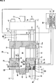
2 stellt einen Formschließzustand einer Formeinheit und einer Formschließvorrichtung in einem Ausführungsbeispiel der vorliegenden Erfindung dar. 2 FIG. 10 illustrates a mold closing state of a mold unit and a mold clamping device in an embodiment of the present invention.
3 stellt einen Formöffnungszustand der Formeinheit und einer Formschließvorrichtung in einem Ausführungsbeispiel der vorliegenden Erfindung dar. 3 FIG. 10 illustrates a mold opening state of the mold unit and a mold clamping apparatus in an embodiment of the present invention.
4 stellt ein Aufbaubeispiel einer Steuereinheit dar. 4 illustrates a structural example of a control unit.
5 stellt die Steuerung einer Formschließkraft, basierend auf einem Begrenzungsmuster eines ersten Ausführungsbeispiels dar. 5 FIG. 12 illustrates the control of a mold clamping force based on a restriction pattern of a first embodiment. FIG.
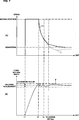
6 stellt die Steuerung einer Formschließkraft, basierend auf einem Begrenzungsmuster eines zweiten Ausführungsbeispiels dar. 6 FIG. 10 illustrates the control of a mold clamping force based on a restriction pattern of a second embodiment. FIG.
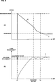
7 stellt die Steuerung einer Formschließkraft, basierend auf einem Begrenzungsmuster eines dritten Ausführungsbeispiels dar. 7 FIG. 16 illustrates the control of a mold clamping force based on a restriction pattern of a third embodiment. FIG.
8 stellt die Steuerung einer Formschließkraft, basierend auf einem Begrenzungsmuster eines vierten Ausführungsbeispiels dar. 8th FIG. 16 illustrates the control of a mold clamping force based on a restriction pattern of a fourth embodiment. FIG.
9 stellt ein modifiziertes Beispiel der vorliegenden Anwendung unter Verwendung eines Rotationsmotors dar, in dem ein Erzeugungsbereich des Magnetfelds durch einen Motorrahmen eingeschlossen wird. 9 FIG. 12 illustrates a modified example of the present application using a rotary motor in which a generation region of the magnetic field is enclosed by a motor frame.
Die Ausführungsbeispiele der vorliegenden Erfindung werden im Folgenden mit Bezugnahme auf die Zeichnungen beschrieben. In Formschließvorrichtungen der Ausführungsbeispiele sind die Richtungen wie folgt bezeichnet. Eine Bewegungsrichtung einer bewegbaren Platte zum Zeitpunkt des Formschließens ist eine Vor wärtsrichtung. Eine Bewegungsrichtung der bewegbaren Platte zu einem Zeitpunkt des Formöffnens ist eine Rückwärtsrichtung. Eine Bewegungsrichtung der Einspritzvorrichtung zu einem Zeitpunkt des Einspritzens ist die Vorwärtsrichtung. Eine Bewegungsrichtung der Einspritzvorrichtung zu einem Zeitpunkt der Dosierung ist die Rückwärtsrichtung.The embodiments of the present invention will be described below with reference to the drawings. In mold clamping devices of the embodiments, the directions are designated as follows. A moving direction of a movable plate at the time of mold closing is a forward direction. A moving direction of the movable plate at a time of mold opening is a backward direction. A direction of movement of the injector at a time of injection is the forward direction. A direction of movement of the injector at a time of metering is the reverse direction.
2 stellt eine Formeinheit und eine Formschließvorrichtung in einem Formschließzustand des Ausführungsbeispiels dar. 3 stellt die Formeinheit und die Formschließvorrichtung in einem Formöffnungszustand des Ausführungsbeispiels dar. 2 FIG. 10 illustrates a mold unit and a mold clamping apparatus in a mold closing state of the embodiment. 3 FIG. 12 illustrates the mold unit and the mold clamping apparatus in a mold opening state of the embodiment. FIG.
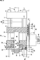
Bezug nehmend auf 2 bezeichnet das Bezugszeichen 10 eine Formklemm- bzw. Formschließvorrichtung, und das Bezugszeichen Fr bezeichnet einen Rahmen einer Spritzgussmaschine. Das Bezugszeichen Gd bezeichnet zwei Führungen als ein erstes Führungsglied, welches eine Schiene konfiguriert, die auf dem Rahmen Fr installiert ist und die Formschließvorrichtung 10 trägt (nur eine der beiden Schienen ist in der 2 dargestellt). Das Bezugszeichen 11 bezeichnet eine feststehende Platte als ein erstes stationäres Glied, das auf der Führung Gd angebracht und an dem Rahmen Fr und der Führung Gd befestigt ist. Eine hintere Platte 13 als ein zweites stationäres Glied ist so angeordnet, dass sie zu der feststehenden Platte 11 weist, wobei ein vorbestimmter Zwischenraum zwischen die feststehende Platte 11 und die hintere Platte 13 eingefügt wird. Führungssäulen 14 als vier Verbindungsglieder sind zwischen der feststehenden Platte 11 und der hinteren Platte 13 aufgespannt (nur zwei der vier Führungssäulen 14 sind dargestellt). Die hintere Platte 13 ist auf der Führung Gd angebracht, um leicht auf der Führung Gd gemeinsam mit dem Ausdehnen und Zusammenziehen der Führungssäulen 14 bewegbar zu sein.Referring to 2 denotes the reference numeral 10 a mold clamping device, and reference character Fr denotes a frame of an injection molding machine. Reference character Gd denotes two guides as a first guide member configuring a rail installed on the frame Fr and the mold clamping device 10 carries (only one of the two rails is in the 2 shown). The reference number 11 denotes a fixed plate as a first stationary member mounted on the guide Gd and fixed to the frame Fr and the guide Gd. A back plate 13 as a second stationary member is arranged to be to the fixed plate 11 points, with a predetermined gap between the fixed plate 11 and the back plate 13 is inserted. guide columns 14 as four links are between the fixed plate 11 and the rear plate 13 spanned (only two of the four guide columns 14 are shown). The back plate 13 is attached to the guide Gd to easily on the guide Gd along with the expansion and contraction of the guide columns 14 to be movable.
In dem Ausführungsbeispiel sind die feststehende Platte 11, die an dem Rahmen Fr und der Führung Gd befestigt ist, und die hintere Platte 13 leicht auf der Führung Gd bewegbar. Es ist jedoch möglich, die hintere Platte 13 an dem Rahmen Fr und der Führung Gd so zu befestigen, dass die feststehende Platte 11 leicht auf der Führung Gd bewegbar ist.In the embodiment, the fixed plate 11 which is fixed to the frame Fr and the guide Gd, and the rear plate 13 easily movable on the guide Gd. It is possible, however, the rear plate 13 to attach to the frame Fr and the guide Gd so that the fixed plate 11 is easily movable on the guide Gd.
Eine bewegbare Platte 12 als ein erstes bewegbares Glied ist so angeordnet, dass sie zu der feststehenden Platte 11 weist, wobei sie zwischen die Führungssäulen 14 eingefügt ist und in den Formöffnungs-/-schließrichtungen bewegbar ist. Daher besitzt die bewegbare Platte 12 Führungslöcher (nicht dargestellt), um zu veranlassen, dass die Führungssäulen bei Teilen hindurchgehen, die den Führungssäulen 14 der bewegbaren Platte 12 entsprechen. A movable plate 12 as a first movable member is arranged to be to the fixed plate 11 points, placing them between the guide columns 14 is inserted and is movable in the mold opening / closing directions. Therefore, the movable plate has 12 Guide holes (not shown) for causing the guide posts to pass through portions of the guide posts 14 the movable plate 12 correspond.
Eine erste Schraube bzw. Schnecke (nicht dargestellt) ist an den Vorderenden der Führungssäulen 14 gebildet. Die Führungssäulen 14 sind an der feststehenden Platte durch Schraubeneingriff der ersten Schraube mit den Muttern n1 befestigt.A first screw (not shown) is at the front ends of the guide columns 14 educated. The guide columns 14 are fixed to the fixed plate by screw engagement of the first screw with the nuts n1.
Führungspfosten 21 als zweite Führungsglieder mit einem Durchmesser der kleiner als der der Führungssäulen 14 ist, sind an vorbestimmten Teilen der Führungssäulen 14 in rückwärtigen Richtungen der Führungssäulen 14 gebildet. Die Führungspfosten 21 sind integral mit den Führungssäulen 14 gebildet und ragen in der rückwärtigen Richtung von der Rückfläche der hinteren Platte 13 hervor. Zweite Schrauben (nicht dargestellt) sind in der Nähe der hinteren Endfläche der hinteren Platte 13 gebildet. Die feststehende Platte 11 und die hintere Platte 13 sind durch Schraubeneingriff der zweiten Schrauben und der Muttern N2 verbunden. In diesem Ausführungsbeispiel sind die Führungspfosten 21 integral mit den Führungssäulen 14 gebildet. Es ist jedoch möglich, die Führungspfosten 21 von den Führungssäulen 14 zu trennen.guidepost 21 as second guide members with a diameter smaller than that of the guide columns 14 is at predetermined parts of the guide columns 14 in the rearward directions of the guide columns 14 educated. The guide posts 21 are integral with the guide columns 14 formed and protrude in the rearward direction from the rear surface of the rear plate 13 out. Second screws (not shown) are near the rear end surface of the rear plate 13 educated. The fixed plate 11 and the back plate 13 are connected by screw engagement of the second screws and nuts N2. In this embodiment, the guide posts 21 integral with the guide columns 14 educated. It is possible, however, the guide posts 21 from the guide columns 14 to separate.
Eine feststehende Form 15 al eine erste Form ist an der feststehenden Platte 11 befestigt. Eine bewegbare Form 16 als eine zweite Form 16 ist an der bewegbaren Platte 12 befestigt. Die feststehende Form 15 und die bewegbare Form 16 werden gemeinsam mit der Bewegung der bewegbaren Form geschlossen und geöffnet, wodurch ein Formschließen, Formklemmen und Formöffnen ausgeführt wird. Mehrere Hohlräume (nicht dargestellt) werden zwischen der feststehenden Form 15 und der bewegbaren Form 16 beim Formklemmen gebildet. Ein Harz (nicht dargestellt) als ein Formmaterial, welches von einer Einspritzdüse 18 der Einspritzvorrichtung 17 eingespritzt wird, füllt die Hohlräume. Eine Formeinheit 19 wird durch die feststehende Form 15 und die bewegbare Form 16 gebildet.A fixed form 15 al a first shape is on the fixed plate 11 attached. A movable form 16 as a second form 16 is on the movable plate 12 attached. The established form 15 and the movable form 16 are closed and opened together with the movement of the movable mold, whereby a mold closing, mold clamping and mold opening is performed. Several cavities (not shown) are placed between the fixed mold 15 and the movable form 16 formed during mold clamping. A resin (not shown) as a molding material discharged from an injection nozzle 18 the injector 17 is injected, fills the cavities. A form unit 19 is determined by the fixed shape 15 and the movable form 16 educated.
Eine Anziehungsplatte 22 als ein zweites bewegbares Glied, die parallel zu der bewegbaren Platte 12 angeordnet ist, ist angeordnet, um entlang der Führungspfosten 21 in der rückwärtigen Richtung der hinteren Platte 13 bewegbar zu sein. Die Anziehungsplatte 22 wird durch die Führungspfosten 21 geführt. Führungslöcher sind in der Anziehungsplatte 22 gebildet, um zu bewirken, dass die Führungspfosten durch die Anziehungsplatte 22 an Teilen hindurchgehe, die den Führungspfosten 21 entsprechen. Die Führungslöcher 23 umfassen einen Teil 24 mit großem Durchmesser, welcher zu einer vorderen Endoberfläche der Anziehungsplatte 22 hin geöffnet ist, und die Kugelmutter n2 unterbringt, und einen Teil 25 mit kleinem Durchmesser, der zu einer hinteren Endoberfläche der Anziehungsplatte 22 hin geöffnet ist, und eine Gleitoberfläche besitzt, die auf den Führungspfosten 21 gleitet. In diesem Ausführungsbeispiel wird die Anziehungsplatte 22 durch die Führungspfosten 21 geführt. Es ist jedoch möglich, die Anziehungsplatte 22 zu führen, wobei nicht nur die Führungspfosten 21, sondern auch die Führung Gd führen.An attraction plate 22 as a second movable member parallel to the movable plate 12 is arranged to be arranged along the guide posts 21 in the rearward direction of the rear plate 13 to be movable. The attraction plate 22 is through the guide posts 21 guided. Guide holes are in the attraction plate 22 formed to cause the guide posts through the attraction plate 22 go through parts of the guide post 21 correspond. The guide holes 23 include a part 24 large diameter leading to a front end surface of the attraction plate 22 is open, and the ball nut n2 accommodates, and a part 25 with a small diameter leading to a rear end surface of the attraction plate 22 is open, and has a sliding surface resting on the guide post 21 slides. In this embodiment, the attraction plate 22 through the guide posts 21 guided. It is possible, however, the attraction plate 22 not just the guide posts 21 but also lead the leadership Gd.
Ein Linearmotor 28 als ein erster Antriebsabschnitt und ein Formöffnungs-/-schließantriebsabschnitt sind zwischen der bewegbaren Platte 12 und dem Rahmen Fr angeordnet, um die bewegbare Platte 12 vorwärts und rückwärts zu bewegen. Der Linearmotor 28 umfasst einen Stator 29 als ein erstes Antriebselement und ein Bewegungsglied 31 als ein zweites Antriebselement. Der Stator 29 ist parallel zu der Führung Gd innerhalb eines Bewegungsbereichs der bewegbaren Platte 12 gebildet. Das Bewegungsglied 31 ist auf einem unteren Ende der bewegbaren Platte 12 innerhalb eines vorbestimmten Bereichs gebildet, um zu dem Stator 29 zu weisen.A linear motor 28 as a first drive portion and a mold opening / closing drive portion are interposed between the movable plate 12 and the frame Fr arranged around the movable plate 12 to move forward and backward. The linear motor 28 includes a stator 29 as a first drive element and a moving member 31 as a second drive element. The stator 29 is parallel to the guide Gd within a range of movement of the movable plate 12 educated. The movement member 31 is on a lower end of the movable plate 12 formed within a predetermined range to the stator 29 to assign.
Das Bewegungsglied 31 umfasst einen Kern 34 und eine Spule 35. Der Kern 34 ragt zu dem Stator 29 hin hervor. Der Kern 34 umfasst mehrere Magnetpolzähne 33 an vorbestimmten Abständen. Die Spulen 35 sind um die Magnetpolzähne 33 herum gewickelt. Die Magnetpolzähne 33 sind senkrecht zu den Bewegungsrichtungen der bewegbaren Platte 12 angeordnet. Die Magnetpolzähne 33 sind parallel zueinander angeordnet. Der Stator 29 umfasst einen Kern (nicht dargestellt) und einen Permanentmagnet (nicht dargestellt), der durch Ausdehnen des Kerns gebildet wird. Der Permanentmagnet wird durch abwechselndes Magnetisieren der Magnetpole in Nord-(N-)Pole und Süd-(S-)Pole an Abständen gebildet, die denen der Magnetpolzähne 33 entsprechen.The movement member 31 includes a core 34 and a coil 35 , The core 34 protrudes to the stator 29 out. The core 34 includes several magnetic pole teeth 33 at predetermined intervals. The spools 35 are around the magnetic pole teeth 33 wrapped around. The magnetic pole teeth 33 are perpendicular to the directions of movement of the movable plate 12 arranged. The magnetic pole teeth 33 are arranged parallel to each other. The stator 29 includes a core (not shown) and a permanent magnet (not shown) formed by expanding the core. The permanent magnet is formed by alternately magnetizing the magnetic poles in north (N) poles and south (S) poles at intervals similar to those of the magnetic pole teeth 33 correspond.
Wenn der Linearmotor 28 durch Liefern eines vorbestimmten Stroms an die Spule 35 angetrieben wird, bewegt sich das Bewegungsglied 31 vorwärts und rückwärts. Daher bewegt sich die bewegbare Platte 12 vorwärts und rückwärts, und zwar gemeinsam mit dem Bewegungsglied 31, wodurch das Schließen und Öffnen der Form ausgeführt wird.If the linear motor 28 by supplying a predetermined current to the coil 35 is driven, the moving member moves 31 forwards and backwards. Therefore, the movable plate moves 12 backwards and forwards, together with the movement member 31 , whereby the closing and opening of the mold is carried out.
Obwohl der Permanentmagnet an dem Stator 29 vorgesehen ist und die Spule 35 an dem Bewegungsglied in dem Ausführungsbeispiel vorgesehen ist, ist es ebenfalls möglich, den Stator mit einer Spule und das Bewegungsglied mit einem Permanentmagnet vorzusehen. In diesem Fall, da sich die Spule nicht bewegt, wenn sich der Linearmotor 28 bewegt, ist es möglich, eine einfache Verkabelung für das Liefern der elektrischen Leistung an die Spule vorzusehen.Although the permanent magnet on the stator 29 is provided and the coil 35 is provided on the moving member in the embodiment, it is also possible to provide the stator with a coil and the moving member with a permanent magnet. In this case, because the coil does not move when the linear motor 28 emotional, For example, it is possible to provide a simple wiring for supplying the electric power to the coil.
Wenn die bewegbare Platte 12 vorwärts bewegt wird und die bewegbare Form 16 in Kontakt mit der feststehenden Form 15 kommt, wird die Form geschlossen und danach zusammengeklemmt. Die Elektromagneteinheit 37 als ein zweiter Antriebsabschnitt und ein Formklemm- bzw. Formschließantriebsabschnitt sind zwischen der hinteren Platte 13 und der Anziehungsplatte 22 angeordnet, um die Form zusammenzuklemmen. Eine Stange 39 als ein Formschließkraftübertragungsglied ist in der Formschließvorrichtung 10 installiert, um vorwärts und rückwärts bewegbar zu sein. Die Stange 39 erstreckt sich durch die hintere Platte 13 und die Anziehungsplatte 22 und verbindet die bewegbare Platte 12 mit der Anziehungsplatte 22. Die Stange 39 bewegt die die Anziehungsplatte 22 gemeinsam mit der Vorwärts- und Rückwärtsbewegung der bewegbaren Platte 12 vorwärts und rückwärts, wenn die Form geschlossen oder geöffnet wird, und überträgt eine Formschließkraft, die durch die Elektromagneteinheit 37 erzeugt wird, auf die bewegbare Platte 12, wenn die Form zusammengeklemmt wird.When the movable plate 12 is moved forward and the movable mold 16 in contact with the fixed mold 15 comes, the mold is closed and then clamped together. The electromagnet unit 37 as a second drive portion and a mold clamping drive portion are between the rear plate 13 and the attraction plate 22 arranged to clamp the mold together. A pole 39 as a mold clamping force transmitting member is in the mold clamping device 10 installed to be movable forwards and backwards. The pole 39 extends through the rear plate 13 and the attraction plate 22 and connects the movable plate 12 with the attraction plate 22 , The pole 39 that moves the attraction plate 22 along with the forward and backward movement of the movable plate 12 forward and backward when the mold is closed or opened, and transmits a mold clamping force passing through the solenoid unit 37 is generated on the movable plate 12 when the mold is pinched.
Die Formschließvorrichtung 10 wird durch die feststehende Platte 11, die bewegbare Platte 12, die hintere Platte 13, die Anziehungsplatte 22, den Linearmotor 28, die Elektromagneteinheit 37, die Stange 39 usw. gebildet.The mold clamping device 10 gets through the fixed plate 11 , the movable plate 12 , the rear plate 13 , the attraction plate 22 , the linear motor 28 , the electromagnet unit 37 , the pole 39 etc. formed.
In der Formschließvorrichtung 10 steuert eine Steuereinheit 60 die Betriebe des Linearmotors 28 als dem Formschließantriebsabschnitt und dem Formöffnungs-/-schließantriebsabschnitt, und die Betriebe der Elektromagneteinheit 37 als dem Formschließantriebsabschnitt. Eine detaillierte Erläuterung der Steuereinheit 60 wird später erfolgen.In the mold clamping device 10 controls a control unit 60 the operations of the linear motor 28 as the mold closing drive section and the mold opening / closing drive section, and the operations of the solenoid unit 37 as the mold closing drive section. A detailed explanation of the control unit 60 will be done later.
Die Elektromagneteinheit 37 umfasst den Elektromagnet 49 als dem ersten Antriebsabschnitt, der auf der Seite der hinteren Platte gebildet ist, und eine Anziehungseinheit 51 als zweiter Antriebsabschnitt, die auf einer Seite der Anziehungsplatte 22 gebildet ist. Die Anziehungseinheit 51 umgibt die Stange 39 an einem vorbestimmten Teil der vorderen Endoberfläche der Anziehungsplatte 22, z. B. der Anziehungsplatte 22 des Ausführungsbeispiels. Die Anziehungseinheit 51 ist an einem Teil gebildet, der zu dem Elektromagnet 49 weist. Zwei Nuten 45 als eine Spulenbereitstellungseinheit mit einer rechteckigen Querschnittsform sind an vorbestimmten Teilen einer hinteren Endoberfläche der hinteren Platte 13 gebildet, z. B. einer Position leicht oberhalb oder unterhalb der Stange 39 in dem Ausführungsbeispiel. Die beiden Nuten 45 sind parallel angeordnet. Die Kerne 46 mit einer rechteckigen Form werden in die Nuten 45 eingeführt. Ferner werden die Jochs 47 in die Räume der Nuten 45 eingeführt. Eine Spule 48 ist um den Kern 46 herum gewickelt.The electromagnet unit 37 includes the electromagnet 49 as the first drive section formed on the side of the rear plate, and an attraction unit 51 as a second drive section, on one side of the attraction plate 22 is formed. The attraction unit 51 surround the pole 39 at a predetermined part of the front end surface of the attraction plate 22 , z. B. the attraction plate 22 of the embodiment. The attraction unit 51 is formed on a part leading to the electromagnet 49 has. Two grooves 45 as a coil supply unit having a rectangular cross-sectional shape are at predetermined parts of a rear end surface of the rear plate 13 formed, z. B. a position slightly above or below the rod 39 in the embodiment. The two grooves 45 are arranged in parallel. The cores 46 with a rectangular shape are in the grooves 45 introduced. Further, the yokes 47 into the spaces of the grooves 45 introduced. A coil 48 is around the core 46 wrapped around.
Der Kern 46 und das Joch 47 können aus einem Gussmetall in einer einstückigen Konstruktion bestehen. Der Kern 46 und das Joch 47 können ebenfalls durch Laminieren dünner Metallbleche gebildet werden, die aus einem ferromagnetischen Material bestehen, um ein elektromagnetisch laminiertes Stahlblech herzustellen.The core 46 and the yoke 47 may consist of a cast metal in a one-piece construction. The core 46 and the yoke 47 may also be formed by laminating thin metal sheets made of a ferromagnetic material to produce an electromagnetically laminated steel sheet.
In dem Ausführungsbeispiel kann der Elektromagnet 49 separat von der hinteren Platte 13 gebildet sein und die Anziehungseinheit 51 kann separat von der Anziehungsplatte 22 gebildet sein. Unterdessen kann der Elektromagnet als ein Teil der hinteren Platte 13 gebildet sein und die Anziehungseinheit kann als ein Teil der Anziehungsplatt 22 gebildet sein.In the embodiment, the electromagnet 49 separately from the rear plate 13 be formed and the attraction unit 51 Can be separated from the attraction plate 22 be formed. Meanwhile, the electromagnet can be considered part of the rear plate 13 be formed and the attraction unit can as a part of the attraction platform 22 be formed.
Wenn ein Strom (ein Gleichstrom) an die Spule 48 der Elektromagneteinheit 37 geliefert wird, wird daher der Elektromagnet 49 angetrieben, um die Anziehungseinheit 51 anzuziehen und die Formschließkraft zu erzeugen.When a current (a direct current) to the coil 48 the electromagnet unit 37 is delivered, therefore, the solenoid 49 driven to the attraction unit 51 to attract and produce the mold clamping force.
Die Stange 39 ist mit der Anziehungsplatte 22 an dem hinteren Endteil der Stange 39 und mit der bewegbaren Platte 12 an dem vorderen Endteil der bewegbaren Platte 12 verbunden. Daher bewegt die Stange 39 die Anziehungsplatte 22 gemeinsam mit der Vorwärtsbewegung der bewegbaren Platte 12 vorwärts, wenn die Form geschlossen wird, und bewegt die Anziehungsplatte 22 gemeinsam mit der Rückwärtsbewegung der bewegbaren Platte 12 rückwärts, wenn die Form geöffnet wird.The pole 39 is with the attraction plate 22 at the rear end part of the rod 39 and with the movable plate 12 at the front end portion of the movable plate 12 connected. Therefore, the rod moves 39 the attraction plate 22 together with the forward movement of the movable plate 12 forward, when the mold is closed, and move the attraction plate 22 together with the backward movement of the movable plate 12 backwards when the mold is opened.
Daher ist ein Loch 41, durch welches die Stange 39 hindurchgeht, an einem Mittelteil der hinteren Platte 13 gebildet, und ein Loch 42, durch welches die Stange 39 hindurchgeht, ist an einem Mittelteil der Anziehungsplatte 22 gebildet. Ein Lager Br1 ist zu einer Öffnung des vorderen Endteils des Lochs 41 weisend, wie ein Buchse zum Tragen der Stange 39, so dass diese frei gleitbar ist, angeordnet. Eine Schnecke bzw. Schraube 43 ist an dem hinteren Endteil der Stange 39 gebildet. Die Schraube 43 und eine Mutter 44 als ein Formdickenanpassungsmechanismus, der durch die Anziehungsplatte 22 getragen wird, um frei drehbar zu sein, werden zusammengeschraubt, um in Eingriff miteinander zu stehen.Therefore, a hole 41 through which the rod 39 passes through, at a central part of the rear plate 13 formed, and a hole 42 through which the rod 39 goes through is at a middle part of the attraction plate 22 educated. A bearing Br1 is at an opening of the front end portion of the hole 41 pointing, like a socket for carrying the rod 39 , so that it is freely slidable, arranged. A screw or screw 43 is at the rear end part of the rod 39 educated. The screw 43 and a mother 44 as a shape thickness adjustment mechanism passing through the attraction plate 22 is carried to be freely rotatable, are screwed together to be engaged with each other.
Ein Zahnrad mit großem Durchmesser (nicht dargestellt) ist auf dem Außenumfang der Mutter 44 gebildet. Ein Formdickenanpassungsmotor (nicht dargestellt) als ein Antriebsabschnitt zum Anpassen der Formdicke ist auf der Anziehungsplatte 22 angeordnet. Ein Zahnrad mit kleinem Durchmesser, das an der Abtriebswelle des Formdickenanpassungsmotors angebracht ist, befindet sich in Zahneingriff mit dem Zahnrad mit großem Durchmesser, das auf dem Außenumfang der Mutter 44 gebildet ist.A large diameter gear (not shown) is on the outer circumference of the nut 44 educated. A shape thickness adjustment motor (not shown) as a drive section for adjusting the mold thickness is on the attraction plate 22 arranged. A small diameter gear mounted on the output shaft of the shape thickness adjusting motor is meshed with the large-diameter gear that is on the outer circumference of the nut 44 is formed.
Wenn der Formdickenanpassungsmotor in Übereinstimmung mit der Dicke der Formeinheit 19 angetrieben wird, wird die Mutter 44 um einen vorbestimmten Winkel gedreht bzw. angetrieben. Dann wird die Position der Stange 39 in Bezug auf die Anziehungsplatte 22 angepasst, um dadurch die Position der Anziehungsplatte 22 in Bezug auf die feststehende Platte 11 und die bewegbare Platte 12 anzupassen. Infolgedessen kann der Spalt δ den optimalen Wert annehmen. Anders ausgedrückt wird durch Verändern der relativen Position zwischen der bewegbaren Plate 12 und der Anziehungsplatte 22 die Formdicke verändert.When the shape thickness adjustment motor in accordance with the thickness of the molding unit 19 is driven, the mother becomes 44 rotated or driven by a predetermined angle. Then the position of the pole 39 in terms of the attraction plate 22 adjusted to thereby the position of the attraction plate 22 in relation to the fixed plate 11 and the movable plate 12 adapt. As a result, the gap δ can take the optimum value. In other words, by changing the relative position between the movable plate 12 and the attraction plate 22 the shape thickness changed.
Der Kern 46, die Jochs 47 und die Anziehungsplatte 22 können in ihrer Gesamtheit aus elektromagnetisch laminierten Stahlblechen bestehen. Unterdessen kann ein Teil der hinteren Platte 13 in der Nähe des Kerns 46 und der Anziehungsplatte 51 aus elektromagnetisch laminierten Stahlblechen bestehen. In diesem Ausführungsbeispiel ist der Elektromagnet 49 auf der hinteren Endoberfläche der hinteren Platte 13 gebildet, und die Anziehungseinheit 51 wird auf der vorderen Endoberfläche der Anziehungsplatte 22 angeordnet, um zu dem Elektromagnet 49 zu weisen. Ferner kann sich die Anziehungseinheit 51 frei vorwärts und rückwärts bewegen. Es ist ebenfalls möglich, die Anziehungseinheit auf der hinteren Endoberfläche der hinteren Platte 13 anzuordnen und den Elektromagnet auf der vorderen Endoberfläche der Anziehungsplatte 22 anzuordnen, so dass er zu der Anziehungseinheit weist. Auf diese Weise kann der Elektromagnet angeordnet werden, so dass er frei vorwärts und rückwärts bewegbar ist.The core 46 , the yokes 47 and the attraction plate 22 may consist in their entirety of electromagnetically laminated steel sheets. Meanwhile, part of the rear plate 13 near the core 46 and the attraction plate 51 consist of electromagnetically laminated steel sheets. In this embodiment, the solenoid is 49 on the rear end surface of the rear plate 13 formed, and the attraction unit 51 becomes on the front end surface of the attraction plate 22 arranged to go to the electromagnet 49 to assign. Furthermore, the attraction unit can 51 move freely forward and backward. It is also possible to have the attraction unit on the rear end surface of the rear plate 13 to arrange and the electromagnet on the front end surface of the attraction plate 22 so that it points to the attraction unit. In this way, the electromagnet can be arranged so that it is freely movable forward and backward.
Als nächstes wird die Steuereinheit 60 im Detail beschrieben. 4 stellt ein Aufbaubeispiel der Steuereinheit dar. Bezug nehmend auf 4 umfasst die Steuereinheit 60 eine obere Steuervorrichtung 61, einen Addierer 62, eine Proportional-Integral-Steuervorrichtung (PI-Steuervorrichtung) 63 als eine Versorgungstromberechnungseinheit, eine Begrenzungsvorrichtung 64 als eine Begrenzungseinheit und einen Verstärker 65. Die Steuereinheit 60 steuert den Antrieb des Linearmotors 28. Ein Antriebssystem des Linearmotors ist jedoch in der 4 weggelassen.Next is the control unit 60 described in detail. 4 FIG. 12 illustrates a structural example of the control unit. Referring to FIG 4 includes the control unit 60 an upper control device 61 , an adder 62 , a proportional integral control device (PI control device) 63 as a supply current calculation unit, a limiting device 64 as a limitation unit and an amplifier 65 , The control unit 60 controls the drive of the linear motor 28 , However, a drive system of the linear motor is in the 4 omitted.
Die obere Steuervorrichtung 61 umfasst eine CPU und einen Speicher oder Ähnliches. Durch Ausführen eines Steuerprogramms durch die CPU, das in einem Speicher gespeichert ist, werden die Betriebe des Linearmotors 28 und des Elektromagnets 49 gesteuert. Die obere Steuervorrichtung 61 gibt einen Befehl (einen Formschließkraftbefehl) aus, der eine Anzeige für den Betrag der Formschließkraft bildet, und einen Befehl (einen Positionsbefehl), der eine Anzeige für eine Position des Linearmotors 28 bildet, zu der sich der Linearmotor geplanter Weise bewegen soll. Der Positionsbefehl wird durch ein Antriebssystem des Linearmotors 28 verarbeitet. Daher wird eine Erläuterung des Befehls hier weggelassen, der eine Anzeige für die Position bildet.The upper control device 61 includes a CPU and a memory or the like. By executing a control program by the CPU stored in a memory, the operations of the linear motor become 28 and the electromagnet 49 controlled. The upper control device 61 outputs a command (a mold clamping force command) indicative of the amount of mold clamping force, and a command (a position command) indicative of a position of the linear motor 28 forms, to which the linear motor is intended to move. The position command is given by a drive system of the linear motor 28 processed. Therefore, an explanation of the command which constitutes an indication of the position is omitted here.
Ein Formklemm- bzw. Formschließkraftbefehl von der oberen Steuervorrichtung 61 wird in den Addierer 62 einer Linearmotorantriebseinheit eingegeben. Ein Wert (ein Formschließkraftdetektionswert), der durch einen Formschließkraftdetektor 55 detektiert wird, der in der Formschließvorrichtung 10 installiert ist, wird in den Addierer 62 eingegeben. Der Addierer 62 berechnet eine Abweichung (einen Formschließkraftfehler) des Detektionswerts der Formschließkraft in Bezug auf den Formschließkraftbefehl, und zwar basierend auf einem Wert (einem Formschließkraftbefehlswert) der Formschließkraft, der durch den Formschließkraftbefehl angezeigt wird, und dem Formschließkraftdetektionswert. Der berechnete Formschließkraftfehler wird in die PI-Steuervorrichtung 63 eingegeben. Der Formschließkraftdetektor 55 kann durch einen Sensor zum Detektieren des Betrags, mit dem die Führungssäule 14 gedehnt ist, einen Lastdetektor, wie beispielsweise einer Kraftmesszelle, die in der Stange 39 installiert ist, oder einem Sensor zum Detektieren eines Magnetflusses zwischen dem Elektromagnet 49 und der Anziehungseinheit 51 gebildet sein.A mold clamping force command from the upper control device 61 gets into the adder 62 entered a linear motor drive unit. A value (a mold clamping force detection value) obtained by a mold clamping force detector 55 detected in the mold clamping device 10 is installed in the adder 62 entered. The adder 62 calculates a deviation (a mold clamping force error) of the detection value of the mold clamping force with respect to the mold clamping force command, based on a value (a mold clamping force command value) of the mold clamping force indicated by the mold clamping force command and the mold clamping force detection value. The calculated mold clamping force error is input to the PI controller 63 entered. The mold closing force detector 55 can be detected by a sensor to detect the amount with which the guide column 14 is stretched, a load detector, such as a load cell, in the bar 39 is installed, or a sensor for detecting a magnetic flux between the electromagnet 49 and the attraction unit 51 be formed.
Die PI-Steuervorrichtung 63 wird beispielsweise durch eine Servokarte gebildet. Ein Stromwert, zum schnellen Korrigieren des Formschließkraftfehlers wird durch die PI-Steuerung (eine Proportional-Integral-Steuerung) basierend auf dem Formschließkraftfehler berechnet, wobei ein Signal (ein Elektromagnetstrombefehl) an die Begrenzungsvorrichtung 64 ausgegeben wird, welches eine Anzeige für den Stromwert bildet. Der Ausdruck des „Stromwerts zum schnellen Korrigieren des Formschließkraftfehlers” bezeichnet einen Stromwert, der es ermöglicht, den Formschließkraftfehler unter Berücksichtigung der unterlegenen Ansprecheigenschaft des Elektromagnets 49 zu korrigieren. Daher ist der Stromwert, der durch die Steuereinheit 63 berechnet wird, nicht immer ein Stromwert, der in eindeutiger Weise für den Formschließfehler bestimmt wird und kann größer als der Stromwert werden.The PI control device 63 is formed for example by a servo card. A current value for quickly correcting the mold clamping force error is calculated by the PI controller (a proportional-integral controller) based on the mold clamping force error, wherein a signal (a solenoid current command) is applied to the limiting apparatus 64 is output, which forms an indication of the current value. The term "current value for quickly correcting the mold clamping force error" means a current value which enables the mold clamping force error to be taken into consideration taking into consideration the inferior response characteristic of the electromagnet 49 to correct. Therefore, the current value provided by the control unit 63 is calculated, not always a current value, which is uniquely determined for the mold closing error and can be greater than the current value.
Die Begrenzungsvorrichtung 64 begrenzt den Stromwert (Eingabestromwert), der durch den Elektromagnetstrombefehl angezeigt wird, welcher von der PI-Steuervorrichtung 63, basierend auf einem Strombegrenzungsmuster, eingegeben wird, welches zuvor eingegeben wurde. Das Strombegrenzungsmuster ist Information (d. h. Information, die eine Anzeige für einen Begrenzungswert eines Versorgungsstroms bildet, der der abgelaufenen Zeit entspricht), die eine Anzeige für die Beziehung zwischen einer Zeit und dem Begrenzungswert des Versorgungsstroms bildet. Daher bestimmt die Begrenzungsvorrichtung 64 den Strombegrenzungswert, der der Zeit entspricht, wenn der Elektromagnetstrombefehl basierend auf dem Begrenzungsmuster eingegeben wird, und gibt den Elektromagnetstrombefehl (einen begrenzten Strombefehl), der eine Anzeige für einen Stromwert bildet, der durch Begrenzen des Eingabewerts erhalten wird, und zwar basierend auf dem Begrenzungswert, an den Verstärker 65 aus. Der Ausdruck des „Begrenzens des Eingabewerts basierend auf dem Begrenzungswert” bezeichnet, dass der Stromwert auf den Begrenzungswert begrenzt ist, wenn der Eingabestromwert den Begrenzungswert übersteigt und der Stromwert wird ausgegeben wie er ist, wenn der Eingabestromwert dem Begrenzungswert entspricht oder niedriger ist.The limiting device 64 limits the current value (input current value) indicated by the solenoid current command received from the PI controller 63 , based on a current limiting pattern, which has been input previously. The current limiting pattern is information (ie, information that forms an indication of a limiting value of a supply current that corresponds to the elapsed time) that provides an indication of the relationship forms between a time and the limit value of the supply current. Therefore, the limiting device determines 64 the current limit value corresponding to the time when the solenoid current command is input based on the restriction pattern, and outputs the solenoid current command (a limited current command) that provides an indication of a current value obtained by limiting the input value based on the limit value , to the amplifier 65 out. The phrase "limiting the input value based on the limiting value" means that the current value is limited to the limiting value when the input current value exceeds the limiting value, and the current value is output as it is when the input current value is equal to or lower than the limiting value.
Der Verstärker 65 wird beispielsweise durch eine Steuerplatine gebildet. Der Verstärker 65 liefert einen Strom in Übereinstimmung mit dem Begrenzungsstrombefehl, der von der Begrenzungsvorrichtung 64 an die Spule 48 des Elektromagnets 49 eingegeben wird. Der Elektromagnet 49 wird ansprechend auf das Liefern des Stroms angetrieben.The amplifier 65 is formed for example by a control board. The amplifier 65 provides a current in accordance with the limiting current command supplied by the limiting device 64 to the coil 48 of the electromagnet 49 is entered. The electromagnet 49 is powered in response to the supply of electricity.
Als nächstes wird eine Beschreibung der Betriebe der Formschließvorrichtung 10 mit dem obigen Aufbau erfolgen.Next, a description will be given of the operations of the mold clamping device 10 done with the above structure.
Die Steuereinheit 60 öffnet und schließt die Form. Wenn die Form geschlossen ist, liefert die Steuereinheit 60 einen Strom an die Spule 35. Nachfolgend wird der Linearmotor 28 angetrieben, um die bewegbare Platte 12 vorwärts zu bewegen. Dann befindet sich die bewegbare Form 16 in Kontakt mit der feststehenden Form 15, wie in 2 dargestellt. Zu diesem Zeitpunkt kann ein optimaler Spalt δ zwischen der hinteren Platte 13 und der Anziehungsplatte 22 gebildet werden, und zwar simultan zwischen dem Elektromagnet 49 und der Anziehungseinheit 51, Die Kraft, die zum Schließen der Form notwendig ist, kann im Vergleich zu der Formschließkraft ausreichend klein werden.The control unit 60 opens and closes the mold. When the mold is closed, the control unit delivers 60 a current to the coil 35 , The following is the linear motor 28 driven to the movable plate 12 to move forward. Then there is the movable mold 16 in contact with the fixed mold 15 , as in 2 shown. At this time, there may be an optimal gap δ between the back plate 13 and the attraction plate 22 be formed, namely simultaneously between the electromagnet 49 and the attraction unit 51 The force necessary to close the mold can become sufficiently small compared to the mold clamping force.
Wenn die bewegbare Platte 12 eine vorbestimmte Position erreicht (wo sich die bewegbare Form 16 in Kontakt mit der feststehenden Form 15 befindet oder leicht vor dem Kontakt mit der feststehenden Form 15 positioniert ist), wird ein Formklemmprozess begonnen. Anders ausgedrückt gibt die obere Steuervorrichtung 61 einen Formschließkraftbefehl, der eine Anzeige eines zuvor eingestellten Sollwerts (im Folgenden als eine Sollformschließkraft bezeichnet) der Formschließkraft bildet, an den Addierer 62 aus. Der Addierer 62 berechnet die Abweichung bzw. den Formschließkraftfehler basierend auf dem Formschließkraftbefehlswert und dem Formschließkraftdetektionswert, der nachfolgend von dem Formschließkraftdetektor eingegeben wird, und gibt den Formschließkraftfehler an die PI-Steuervorrichtung 63 aus. Die PI-Steuervorrichtung 63 korrigiert den Formschließkraftfehler durch eine PI-Steuerung. Die PI-Steuervorrichtung 63 berechnet einen Stromwert, der an den Elektromagnet 49 geliefert wird, um den Formschließkraftfehler zu vermeiden, und gibt den Elektromagnetstrombefehl an die Begrenzungsvorrichtung 64 aus. Die Begrenzungsvorrichtung 64 begrenzt den Elektromagnetstrombefehl unter Verwendung eines Stromwerts der der abgelaufenen Zeit entspricht, und gibt den begrenzten Strombefehl an den Verstärker 65 aus. Der Verstärker 65 liefert den Strom in Übereinstimmung mit dem begrenzten Strombefehl an die Spule 48 des Elektromagnets 49 aus.When the movable plate 12 reaches a predetermined position (where the movable mold 16 in contact with the fixed mold 15 or slightly before contact with the fixed mold 15 is positioned), a mold clamping process is started. In other words, the upper control device gives 61 a mold clamping force command indicative of a previously set value (hereinafter referred to as a target mold clamping force) of the mold clamping force to the adder 62 out. The adder 62 calculates the deviation or the mold clamping force error based on the mold clamping force command value and the mold clamping force detection value subsequently inputted from the mold clamping force detector, and outputs the mold clamping force error to the PI control device 63 out. The PI control device 63 corrects the mold clamping force error by PI control. The PI control device 63 calculates a current value that goes to the electromagnet 49 is supplied to avoid the mold clamping force error, and outputs the solenoid current command to the limiting device 64 out. The limiting device 64 limits the solenoid current command using a current value equal to the elapsed time, and gives the limited current command to the amplifier 65 out. The amplifier 65 supplies the current to the coil in accordance with the limited current command 48 of the electromagnet 49 out.
Durch Liefern des Stroms an die Spule 48 wird der Elektromagnet 49 angetrieben, um die Anziehungseinheit 51 durch die Anziehungskraft des Elektromagnets 49 anzuziehen. Simultan wird die Formklemm- bzw. Formschließkraft auf die bewegbare Platte 12 über die Anziehungsplatte 22 und die Stangen 39 übertragen. Auf diese Weise wird die Form zusammengeklemmt.By supplying the current to the coil 48 becomes the electromagnet 49 driven to the attraction unit 51 by the attraction of the electromagnet 49 to attract. Simultaneously, the mold clamping force on the movable plate becomes 12 about the attraction plate 22 and the rods 39 transfer. In this way, the mold is clamped together.
Die Steuereinheit 60 liefern einen Strom (im Folgenden als ein Nennstrom bezeichnet), der einen Stromwert übersteigt, der der Sollformschließkraft entspricht, nachdem der Formschließkraftbefehl ausgegeben wird, um ein Anstiegsansprechverhalten der Formschließkraft zu verbessern. Genau gesagt zeigt unmittelbar bei und nach Initiierung des Formklemmens, wenn der Formschließkraftfehler groß ist, ein von der PI-Steuervorrichtun 63 ausgegebener Strombefehl einen Stromwert an, der den Nennstrom übersteigt. Wenn jedoch der Strom, der den Nennstrom übersteigt, kontinuierlich an die Spule geliefert wird, wird eine Formschließkraft erzeugt, die einen zulässigen Abweichungsbereich für die Sollformschließkraft (Überschießen der Formschließkraft) übersteigt. Daher steuert die Steuereinheit 60 dieses Ausführungsbeispiels die Formschließvorrichtung, um das Überschießen der Formschließkraft zu verhindern. Diese Steuerung wird realisiert, wenn die Begrenzungsvorrichtung den Versorgungsstrom begrenzt, und zwar basierend auf einem Begrenzungsmuster. Die detaillierte Beschreibung des Begrenzungsmusters wird später erfolgen.The control unit 60 supply a current (hereinafter referred to as a rated current) exceeding a current value corresponding to the target mold clamping force after the mold clamping force command is issued to improve a rise-up response of the mold clamping force. Specifically, immediately upon and after the initiation of the mold clamping, when the mold clamping force error is large, one of the PI control apparatus shows 63 output current command to a current value that exceeds the rated current. However, when the current exceeding the rated current is continuously supplied to the coil, a mold clamping force exceeding an allowable deviation range for the target mold clamping force (overshoot of the mold clamping force) is generated. Therefore, the control unit controls 60 This embodiment, the mold clamping device to prevent the overshoot of the mold clamping force. This control is realized when the limiting device limits the supply current based on a limiting pattern. The detailed description of the boundary pattern will be made later.
Nachdem die Sollformschließkraft während des Formklemmprozesses erhalten wird, wird nachfolgend der Formschließkraftdetektionswert, der durch den Formschließkraftdetektor 55 detektiert wird, in den Addierer 62 eingegeben. Der Strom, der an die Spule 48 geliefert wird, wird angepasst, um die Formschließkraft durch den Addierer 62, die PI-Steuervorrichtung 63, die Begrenzungsvorrichtung 64 und den Verstärker 65 innerhalb des zulässigen Abweichungsbereichs der Sollformschließkraft zu halten, um dadurch eine Rückkopplungssteuerung auszuführen. Bei dieser Gelegenheit wird ein Harz, das durch die Einspritzvorrichtung 17 geschmolzen wurde, von der Einspritzdüse 18 eingespritzt und in Hohlräume der Formeinheit 19 gefüllt.After the target mold clamping force is obtained during the mold clamping process, subsequently, the mold clamping force detection value obtained by the mold clamping force detector becomes 55 is detected in the adder 62 entered. The current flowing to the coil 48 is adjusted to the mold clamping force by the adder 62 , the PI control device 63 , the limiting device 64 and the amplifier 65 within the allowable deviation range of the target mold clamping force, thereby providing feedback control perform. On this occasion, a resin is injected through the injector 17 was melted from the injector 18 injected and in cavities of the molding unit 19 filled.
Wenn das Harz in den Hohlräumen gekühlt und ausgehärtet wird, hält die Steuereinheit 60 das Liefern des Stroms zu einem Zeitpunkt des Öffnens der Form in einem Zustand an, der in 2 dargestellt ist. Zur gleichen Zeit wird der Linearmotor 28 angetrieben, um die bewegbare Platte 12 rückwärts zu bewegen. 3 stellt einen Formöffnungszustand dar, in dem die bewegbare Form 16 an der hintersten Position angeordnet wird.When the resin in the cavities is cooled and hardened, the control unit stops 60 supplying the current at a time of opening the mold in a state that is in 2 is shown. At the same time, the linear motor 28 driven to the movable plate 12 move backwards. 3 represents a mold opening state in which the movable mold 16 is arranged at the rearmost position.
Als nächstes wird eine Steuerung der Formschließkraft basierend auf dem Begrenzungsmuster beschrieben. 5 stellt eine Steuerung der Formschließkraft basierend auf dem Begrenzungsmuster eines ersten Ausführungsbeispiels dar.Next, a control of the mold clamping force based on the restriction pattern will be described. 5 FIG. 12 illustrates a control of the mold clamping force based on the restriction pattern of a first embodiment. FIG.
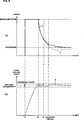
Bezug nehmend auf 5A stellt die Abszissenachse die abgelaufene Zeit und die Ordinatenachse einen Stromwert dar, der an einen Elektromagnet angelegt wird. Die durchgezogene Linie stellt ein Begrenzungsmuster dar, welches durch die Begrenzungsvorrichtung 64 eingestellt wird. Die gestrichelte Linie I stellt einen Stromwert dar, der tatsächlich von dem Verstärker 65 an die Spule 48 des Elektromagnets 49 geliefert wird.Referring to 5A For example, the abscissa axis represents the elapsed time and the ordinate axis represents a current value applied to an electromagnet. The solid line represents a limiting pattern, which by the limiting device 64 is set. The dashed line I represents a current value that is actually from the amplifier 65 to the coil 48 of the electromagnet 49 is delivered.
Bezug nehmend auf 5B stellt die Abszissenachse die abgelaufene Zeit synchronisiert mit der Abszissenachse der 5A dar, und die Ordinatenachse stellt den Wert der Formschließkraft (den Formschließkraftdetektionswert) dar. Die Linie F stellt eine Übertragung der Formschließkraft mit der jeweils abgelaufenen Zeit dar.Referring to 5B the axis of abscissa represents the elapsed time synchronized with the axis of abscissa 5A and the ordinate axis represents the value of the mold clamping force (the mold clamping force detection value). The line F represents a transmission of the mold clamping force with the elapsed time each.
Wie in 5(A) dargestellt, ist das Begrenzungsmuster L1 in dem ersten Ausführungsbeispiel so definiert, dass der Begrenzungswert unmittelbar auf den Nennstrom zu einem Zeitpunkt t2 abfällt. Der Zeitpunkt t2 liegt hinter dem Erreichen der Formschließkraft F des zulässigen Abweichungsbereichs (im Folgenden als eine zulässige Formschließkraft bezeichnet) der Sollformschließkraft und bevor die Formschließkraft F die zulässige Formschließkraft übersteigt, so dass ein Überschießen verursacht wird.As in 5 (A) 1, the limiting pattern L1 in the first embodiment is defined so that the limiting value directly falls to the rated current at a time t2. The point of time t2 is beyond the attainment of the mold clamping force F of the allowable deviation range (hereinafter referred to as an allowable mold clamping force) of the target mold clamping force and before the mold clamping force F exceeds the allowable mold clamping force to cause overshoot.
Wie beschrieben wird das Begrenzungsmuster zuvor eingestellt, so dass der Versorgungsstrom zu einem Zeitpunkt verringert wird, wenn die Formschließkraft die Sollformschließkraft erreicht. Daher kann der Strom in Übereinstimmung mit dem Begrenzungsmuster geliefert werden, obwohl der Elektromagnet, der ein langsames Ansprechverhalten aufweist, eine Rückkopplungssteuerung durchläuft. Infolgedessen kann das Überschießen der Formschließkraft verhindert werden.As described, the restriction pattern is previously set so that the supply current is decreased at a time when the mold clamping force reaches the target mold clamping force. Therefore, although the solenoid having a slow response undergoes feedback control, the current can be supplied in accordance with the limiting pattern. As a result, the overshoot of the mold clamping force can be prevented.
Unten beschrieben wird die Steuerung der Formschließkraft F, die durch die Steuereinheit 60 ausgeführt wird, und zwar in einem Fall wo das Begrenzungsmuster in der Begrenzungsvorrichtung 64 eingestellt wird.Described below is the control of the mold clamping force F generated by the control unit 60 is executed, in a case where the restriction pattern in the restriction device 64 is set.
Für eine Zeit lang wird nach der Initiierung (t1) des Formklemmens zur Verbesserung eines Anstiegsansprechverhaltens der Formschließkraft, ein Strombefehl, der eine Anzeige eines Stromwerts des maximalen Stroms (des maximalen Stroms, der von dem Verstärker 65 an den Elektromagnet 49 innerhalb eines Bereichs geliefert werden kann, in dem die Betriebe einer Vorrichtung in geeigneter Weise sichergestellt werden) bildet, oder mehr von der PI-Steuervorrichtung 63 ausgegeben. Daher wird ein begrenzter Strombefehl in Übereinstimmung mit dem Begrenzungsmuster L1 durch die Begrenzungsvorrichtung 64 an den Verstärker 65 ausgegeben und ein Strom wird ansprechend auf den begrenzten Strombefehl an die Spule 48 des Elektromagnets 49 geliefert. Die durchgezogene Linie L1 und die gestrichelte Linie I überlappen sich zwischen dem Zeitpunkt t1 und einem Zeitpunkt ts.For a while after the initiation (t1) of the mold clamping for improving a rise-up response of the mold clamping force, a current command indicative of a current value of the maximum current (the maximum current supplied from the amplifier 65 to the electromagnet 49 can be provided within a range in which the operations of a device are suitably ensured) or more from the PI control device 63 output. Therefore, a limited current command in accordance with the limiting pattern L1 by the limiting device 64 to the amplifier 65 output and a current is responsive to the limited current command to the coil 48 of the electromagnet 49 delivered. The solid line L1 and the broken line I overlap between the time t1 and a time ts.
Durch Liefern des Stroms in Übereinstimmung mit dem Begrenzungsmuster, wird der maximale Strom an die Spule 48 für eine Zeit lang nach der Initiierung (t1) des Formklemmens geliefert. Durch Liefern des maximalen Stroms erhöht sich die Formklemm- bzw. Formschließkraft F mit einem guten Ansprechverhalten im Vergleich zu einem Fall, wo der Nennstrom geliefert wird. Zu dem Zeitpunkt t2 nähert sich die Formschließkraft dem oberen Grenzwert der zulässigen Formschließkraft an oder erreicht diesen.By supplying the current in accordance with the limiting pattern, the maximum current becomes to the coil 48 for a while after initiation (t1) of mold clamping. By supplying the maximum current, the mold clamping force F increases with a good response as compared with a case where the rated current is supplied. At the time t2, the mold clamping force approaches or reaches the upper limit of the allowable mold clamping force.
Im Fall einer gewöhnlichen Rückkopplungssteuerung ohne Vorsehen der Begrenzungsvorrichtung 64 kann der Strom nicht unmittelbar abfallen, selbst nachdem die Formschließkraft die Sollformschließkraft zum Zeitpunkt t2 annimmt. Dies geschieht aufgrund einer Verzögerung der Rückkopplungssteuerung. Infolgedessen überschießt die Formschließkraft in dem Fall der Verwendung von lediglich der gewöhnlichen Rückkopplungssteuerung. Das Begrenzungsmuster wird jedoch verwendet, um das Überschießen in dem Ausführungsbeispiel zu verhindern. Daher wird der Strom so geliefert, dass er nicht den Grenzwert des Begrenzungsmusters nach dem Zeitpunkt t2 übersteigt, und zwar bis die Formschließkraft F nicht den zulässigen Abweichungsbereich übersteigt. Daher wird der Nennstrom ab dem Zeitpunkt t2 und danach geliefert. Als eine Folge davon nimmt die Formschließkraft F ab und wird innerhalb der zulässigen Formschließkraft gehalten um einen statischen Zustand einzunehmen.In the case of ordinary feedback control without providing the restriction device 64 For example, the current can not drop immediately even after the mold clamping force becomes the target mold clamping force at time t2. This happens due to a delay of the feedback control. As a result, the mold clamping force overshoots in the case of using only the ordinary feedback control. However, the restriction pattern is used to prevent the overshoot in the embodiment. Therefore, the current is supplied so as not to exceed the limit value of the limiting pattern after the time t2, until the mold clamping force F does not exceed the allowable deviation range. Therefore, the rated current is supplied from time t2 and thereafter. As a result, the mold clamping force F decreases and is held within the allowable mold clamping force to take a static state.
Die Formschließkraft F wird nachfolgend durch den Formschließkraftdetektor 55 detektiert und wird in den Addierer 62 eingegeben. Der Addierer 62 berechnet nachfolgend eine Abweichung (Formschließkraftfehler) der Formschließkraft in Bezug auf die Sollformschließkraft und gibt den Formschließkraftfehler an die PI-Steuervorrichtung 63 aus. Wenn der Formschließkraftfehler verringert wird, kann daher ein Fall auftreten, wo der Stromwert, der durch den Strombefehl angezeigt wird, der durch die PI-Steuervorrichtung 63 ausgegeben wird, die rückkopplungsgesteuert ist, kleiner als der durch das Begrenzungsmuster I wird. In diesem Fall läuft der Strombefehl von der PI-Steuervorrichtung 63 durch die Begrenzungsvorrichtung 64 hindurch, und zwar ohne begrenzt zu werden, und wird in den Verstärker 65 eingegeben. Der Strom wird von dem Verstärker 65 an die Spule 48 in Übereinstimmung mit dem Strombefehl ausgegeben. The mold clamping force F is subsequently determined by the mold clamping force detector 55 detected and becomes the adder 62 entered. The adder 62 subsequently calculates a deviation (mold clamping force error) of the mold clamping force with respect to the target mold clamping force, and outputs the mold clamping force error to the PI controller 63 out. Therefore, when the mold clamping force error is reduced, there may occur a case where the current value indicated by the current command is that provided by the PI controller 63 which is feedback-controlled becomes smaller than that through the limiting pattern I. In this case, the current command is executed by the PI controller 63 through the limiting device 64 through, without being limited, and gets into the amp 65 entered. The electricity is from the amplifier 65 to the coil 48 issued in accordance with the current command.
Der obige Zustand tritt zum Zeitpunkt ts und danach auf. Nach dem Zeitpunkt ts wird der Versorgungsstrom I von dem Begrenzungsmuster L1 getrennt und wird ein Wert der kleiner als der Begrenzungs- bzw. Grenzwert ist. Nach dem Zeitpunkt ts wird die Rückkopplungssteuerung wirksam ohne durch die Begrenzungsvorrichtung 64 begrenzt zu werden. Dann wird die Formschließkraft F aufrechterhalten, um eine zulässige Formschließkraft zu sein.The above state occurs at time ts and after. After the time ts, the supply current I is disconnected from the limiting pattern L1 and becomes a value smaller than the limit value. After the time ts, the feedback control becomes effective without the restriction device 64 to be limited. Then, the mold clamping force F is maintained to be an allowable mold clamping force.
Wie beschrieben, liefert die Formschließvorrichtung 10 des ersten Ausführungsbeispiels den Versorgungsstrom (den maximalen Strom), der größer als der Nennstrom ist, unmittelbar bei und nach der Initiierung des Formklemmens, um dadurch den Strom an den Elektromagnet 49 zu liefern, und zwar basierend auf dem Begrenzungsmuster, durch welches der Versorgungsstrom auf den Nennstrom abnimmt, bevor ein Überschießen der Formschließkraft stattfindet. Daher ist es möglich, die Wahrscheinlichkeit des Hervorrufens des Überschießens zu verringern, während das Anstiegsansprechverhalten verbessert wird.As described, the mold clamping device provides 10 of the first embodiment, the supply current (the maximum current), which is greater than the rated current, immediately after and after the initiation of the mold clamping, thereby the current to the solenoid 49 based on the restriction pattern by which the supply current decreases to the rated current before overshoot of the mold clamping force takes place. Therefore, it is possible to reduce the likelihood of causing the overshoot while improving the rise-up response.
In dem ersten Ausführungsbeispiel fällt die Formschließkraft (unterschwingt) aus dem zulässigen Abweichungsbereich nachdem die Formschließkraft einmal in den zulässigen Abweichungsbereich kommt, und zwar ansprechend auf den Abfall des Versorgungsstroms. Infolgedessen erfordert es Zeit bis die Formschließkraft in den zulässigen Abweichungsbereich fällt. Daher besteht ein Problem, dass eine Zeitdauer von der Initiierung des Formklemmens zu einem Zeitpunkt, an dem der statische Zustand realisiert wird, lang wird. Ein zweites Ausführungsbeispiel wird als nächstes als ein Beispiel zur Lösung des Problems beschrieben.In the first embodiment, the mold clamping force (undershoot) falls outside the allowable deviation range after the mold clamping force once comes within the allowable deviation range, in response to the drop in the supply current. As a result, it takes time for the mold clamping force to fall within the allowable deviation range. Therefore, there is a problem that a period of time from the initiation of the mold clamping at a time when the static state is realized becomes long. A second embodiment will next be described as an example for solving the problem.
6 stellt eine Steuerung einer Formklemm- bzw. Formschließkraft dar, und zwar basierend auf einem Begrenzungsmuster des zweiten Ausführungsbeispiels. In 6 sind die gleichen Bezugszeichen Teilen zugeordnet, die die gleichen wie die in 5 sind, und die Beschreibung dieser Teile wird weggelassen. 6 FIG. 12 illustrates a control of a mold clamping force based on a restriction pattern of the second embodiment. In 6 the same reference numerals are assigned to parts that are the same as those in 5 are, and the description of these parts is omitted.
Bezug nehmend auf 6(A) ist das Begrenzungsmuster L1 des zweiten Ausführungsbeispiels so definiert, dass ein Begrenzungswert zu einem Zeitpunkt t2 beginnt abzunehmen. Der Zeitpunkt 12 liegt hinter dem Zeitpunkt an dem die Formschließkraft F eine zulässige Formschließkraft erreicht und bevor die Formschließkraft F die zulässige Formschließkraft übersteigt, also überschießt. Der Grenzwert nimmt jedoch nicht unmittelbar auf einen Nennstrom ab. Und zwar ist der Grenzwert definiert, um graduell abzunehmen und sanft den Nennstrom zu erreichen. Wenn der Versorgungsstrom unmittelbar verringert wird, wird die Formschließkraft eine zulässige Formschließkraft oder weniger, ebenfalls wie in dem ersten Ausführungsbeispiel beschrieben. Daher erfordert es mehr Zeit letztlich einen statischen Zustand zu erreichen (einen Zustand, in dem die Formschließkraft stabil aufrecht erhalten wird, um eine zulässige Formschließkraft zu sein).Referring to 6 (A) For example, the limiting pattern L1 of the second embodiment is defined so that a limiting value starts to decrease at a time t2. Point of time 12 is behind the time at which the mold clamping force F reaches an allowable mold clamping force and before the mold clamping force F exceeds the allowable mold clamping force, so overshoots. However, the limit does not decrease directly to a rated current. Namely, the limit is defined to gradually decrease and gently reach the rated current. When the supply current is immediately reduced, the mold clamping force becomes an allowable mold clamping force or less, also as described in the first embodiment. Therefore, it takes more time to finally reach a static state (a state in which the mold clamping force is stably maintained to be an allowable mold clamping force).
Wie beschrieben, wird das Begrenzungsmuster zuvor so bestimmt, dass der Versorgungsstrom zu einer Zeit verringert wird, wenn die Formschließkraft den zulässigen Abweichungsbereich erreicht. Daher kann der Strom in Übereinstimmung mit dem Begrenzungsmuster geliefert werden, obwohl der Elektromagnet, der ein langsames Ansprechverhalten aufweist, eine Rückkapplungssteuerung durchläuft. Infolgedessen kann das Überschießen der Formschließkraft verhindert werden.As described, the restriction pattern is previously determined so that the supply current is reduced at a time when the mold clamping force reaches the allowable deviation range. Therefore, although the solenoid having slow response undergoes feedback control, the current may be supplied in accordance with the restriction pattern. As a result, the overshoot of the mold clamping force can be prevented.
Unten beschrieben ist die Steuerung der Formschließkraft F, die durch eine Steuereinheit 60 in einem Fall ausgeführt wird, wo das Begrenzungsmuster L1 in einer Begrenzungsvorrichtung 64 eingestellt wird.Described below is the control of the mold clamping force F by a control unit 60 in a case where the restriction pattern L1 is in a restriction device 64 is set.
Für eine Zeit lang nach der Initiierung (t1) des Formklemmens, wird ein Strombefehl, der eine Anzeige für einen Stromwert des maximalen Stroms oder mehr bildet, durch eine PI-Steuervorrichtung 63 an die Begrenzungsvorrichtung 64 ausgegeben, wodurch ein Anstiegsansprechverhalten der Formschließkraft verbessert wird.For a while after the initiation (t1) of the mold clamping, a current command indicative of a current value of the maximum current or more is generated by a PI controller 63 to the limiting device 64 output, whereby a rising response of the mold clamping force is improved.
Daher wird der begrenzte Strombefehl in Übereinstimmung mit dem Begrenzungsmuster L1 durch die Begrenzungsvorrichtung 64 an den Verstärker 65 ausgegeben, und ein Strom wird ansprechend auf den begrenzten Strombefehl an eine Spule 48 des Elektromagnets 49 geliefert. Eine durchgezogene Linie L1 und eine gestrichelte Linie I überlappen einander zwischen dem Zeitpunkt t1 und einem Zeitpunkt ts.Therefore, the limited current command becomes in accordance with the limiting pattern L1 by the limiting device 64 to the amplifier 65 output, and a current is responsive to the limited current command to a coil 48 of the electromagnet 49 delivered. A solid line L1 and a broken line I overlap each other between the time t1 and a time ts.
Durch Liefern des Stroms in Übereinstimmung mit dem Begrenzungsmuster L1 wird der maximale Strom an die Spule 48 für eine Zeit nach der Iniitierung (t1) des Formklemmens geliefert. Durch Liefern des maximalen Stroms steigt die Formschließkraft F mit einem guten Ansprechverhalten im Vergleich zu einem Fall an, wo der Nennstrom geliefert wird. Zu dem Zeitpunkt t2 nähert sich die Formschließkraft dem oberen Begrenzungswert der zulässigen Formschließkraft an oder erreicht diesen. By supplying the current in accordance with the limiting pattern L1, the maximum current becomes to the coil 48 for a time after the initialization (t1) of the mold clamping. By supplying the maximum current, the mold clamping force F increases with a good response compared to a case where the rated current is supplied. At the time t2, the mold clamping force approaches or reaches the upper limit value of the allowable mold clamping force.
Im Fall einer gewöhnlichen Rückkopplungssteuerung ohne Vorsehen der Begrenzungsvorrichtung 64 kann der Strom nicht unmittelbar abfallen, selbst nachdem die Formschließkraft die Sollformschließkraft zum Zeitpunkt t2 erreicht. Dies geschieht aufgrund einer Verzögerung einer Rückkopplungssteuerung. Das Begrenzungsmuster ist jedoch in dem Ausführungsbeispiel vorgesehen. Daher wird der Strom so geliefert, dass er nicht einen Grenzwert des Begrenzungsmusters übersteigt. Daher beginnt nach dem Zeitpunkt t2 der Versorgungsstrom in Übereinstimmung mit dem Begrenzungsmuster abzunehmen. Anders ausgedrückt nimmt der Versorgungsstrom nicht unmittelbar auf den Nennstrom ab und nimmt mit einer graduell mit einer Abnahmerate (einer abnehmenden Rate) ab. Infolgedessen nimmt die Formschließkraft F nicht mehr als notwendig ab und wird innerhalb der zulässigen Formschließkraft gehalten, um einen statischen Zustand innerhalb einer zulässigen Zeit tp einzunehmen.In the case of ordinary feedback control without providing the restriction device 64 For example, the current can not drop immediately even after the mold clamping force reaches the target mold clamping force at time t2. This happens due to a delay of a feedback control. However, the restriction pattern is provided in the embodiment. Therefore, the current is supplied so as not to exceed a limit value of the limiting pattern. Therefore, after time t2, the supply current begins to decrease in accordance with the restriction pattern. In other words, the supply current does not decrease directly to the rated current and gradually decreases at a rate of decrease (a decreasing rate). As a result, the mold clamping force F does not decrease more than necessary and is kept within the allowable mold clamping force to take a static state within an allowable time tp.
Die Formschließkraft F wird sukzessive durch den Formschließkraftdetektor 55 detektiert und wird in einen Addierer 62 eingegeben. Der Addierer 62 berechnet sukzessive eine Abweichung (den Formschließkraftfehler) der Formschließkraft F in Bezug auf die Sollformschließkraft und gibt den Formschließkraftfehler an die PI-Steuervorrichtung 63 aus. Wenn der Formschließkraftfehler verringert wird, kann daher ein Fall auftreten, wo der Stromwert, der durch den Strombefehl angezeigt wird, durch die PI-Steuervorrichtung 63 ausgegeben wird, welche rückkopplungsgesteuert ist, kleiner als der durch das Begrenzungsmuster I wird. In diesem Fall geht der Strombefehl von der PI-Steuervorrichtung 63 durch die Begrenzungsvorrichtung 63 hindurch ohne begrenzt und in den Verstärker 65 eingegeben zu werden. Der Strom wird durch den Verstärker 65 an die Spule 48 in Übereinstimmung mit dem Strombefehl ausgegeben.The mold clamping force F is successively passed through the mold clamping force detector 55 detected and becomes an adder 62 entered. The adder 62 Successively calculates a deviation (the mold clamping force error) of the mold clamping force F with respect to the target mold clamping force and outputs the mold clamping force error to the PI controller 63 out. Therefore, when the mold clamping force error is reduced, there may occur a case where the current value indicated by the current command is detected by the PI controller 63 is output, which is feedback controlled, smaller than that by the limiting pattern I is. In this case, the current command goes from the PI controller 63 through the limiting device 63 through without being limited and into the amplifier 65 to be entered. The current is through the amplifier 65 to the coil 48 issued in accordance with the current command.
Ein derartiger Zustand tritt zum Zeitpunkt ts und danach auf. Nach dem Zeitpunkt ts wird der Versorgungsstrom I von dem Begrenzungsmuster L1 getrennt und nimmt einen Wert an, der kleiner als der Begrenzungswert ist. Nach dem Zeitpunkt ts wird die Rückkopplungssteuerung wirksam, ohne durch die Begrenzungsvorrichtung 64 begrenzt zu werden. Dann wird die Formschließkraft F aufrecht erhalten, um eine zulässige Formschließkraft zu sein.Such a condition occurs at time ts and after. After the time ts, the supply current I is separated from the limiting pattern L1 and assumes a value smaller than the limiting value. After the time ts, the feedback control becomes effective without passing through the restriction device 64 to be limited. Then, the mold clamping force F is maintained to be an allowable mold clamping force.
Wie beschrieben, liefert die Formschließvorrichtung 10 des zweiten Ausführungsbeispiels den Versorgungsstrom (den maximalen Strom), der größer als der Nennstrom ist, unmittelbar bei und nach der Initiierung des Formklemmens, um dadurch Strom an den Elektromagnet 49 zu liefern, und zwar basierend auf dem Begrenzungsmuster nach dem der Versorgungsstrom mit einer vorbestimmten Verringerungsrate abnimmt, bevor die Formschließkraft überschießt. Daher ist es möglich, eine Wahrscheinlichkeit zu verringern, dass das Überschießen auftritt, während das Anstiegsansprechverhalten verbessert wird. Ferner ist es möglich, das Unterschießen der Formschließkraft zu verhindern, um dadurch den statischen Zustand der Formschließkraft innerhalb der zulässigen Zeit zu realisieren.As described, the mold clamping device provides 10 of the second embodiment, the supply current (the maximum current), which is greater than the rated current, immediately at and after the initiation of the mold clamping, thereby current to the solenoid 49 based on the restriction pattern after which the supply current decreases at a predetermined rate of decrease before the mold clamping force overshoots. Therefore, it is possible to reduce a likelihood that overshoot will occur while improving the slew rate response. Further, it is possible to prevent the undershoot of the mold clamping force to thereby realize the static state of the mold clamping force within the allowable time.
Obwohl das Begrenzungsmuster L1 für die Initialisierung t1 des Formklemmens oder später vorgesehen ist, ist es ebenfalls möglich, dieses nicht für eine Zeitdauer von dem Zeitpunkt t1 bis t2 vorzusehen, und das Begrenzungsmuster für den Zeitpunkt 12 oder später vorzusehen. Dies deshalb, da der maximale Strom als der Grenzwert des Begrenzungsmusters für den Zeitpunkt t1 bis zum Zeitpunkt t2 eingestellt ist, was nicht in ausreichender Weise als der Grenzwert fungiert.Although the restriction pattern L1 is provided for the initialization t1 of the mold clamping or later, it is also possible not to provide it for a period from the time t1 to t2, and the limiting pattern for the timing 12 or later. This is because the maximum current is set as the limit value of the limiting pattern for the time t1 to the time t2, which does not sufficiently function as the limit value.
Das Begrenzungsmuster L1 des zweiten Ausführungsbeispiels ist dahingehend kompliziert, dass es viele Knoten von einer Zeit des Erzeugens des maximalen Stroms zu einer Zeit der Verringerung des Nennstroms besitzt. Infolgedessen besteht eine Wahrscheinlichkeit, dass die Formschließkraft instabil wird. Bezug nehmend auf 6(B) steigt die Formschließkraft innerhalb des zulässigen Abweichungsbereichs nach dem Zeitpunkt t2 an und fällt ab. 6(B) zeigt, dass die Formschließkraft instabil ist. Ferner besteht ein Problem, dass die Knoten nicht in einfacher Weise bestimmt werden können. Ein drittes Ausführungsbeispiel wird als nächstes als ein Beispiel zum Lösen dieses Problems beschrieben.The limiting pattern L1 of the second embodiment is complicated in that it has many nodes from a time of generating the maximum current at a time of decreasing the rated current. As a result, there is a probability that the mold clamping force becomes unstable. Referring to 6 (B) the mold clamping force increases within the allowable deviation range after the time t2 and drops. 6 (B) shows that the mold clamping force is unstable. Further, there is a problem that the nodes can not be easily determined. A third embodiment will next be described as an example for solving this problem.
7 stellt eine Steuerung einer Formschließkraft basierend auf einem Begrenzungsmuster des dritten Ausführungsbeispiels dar. In 7 sind die gleichen Bezugszeichen den gleichen Teilen wie denen zugewiesen, die in 6 dargestellt sind und eine Beschreibung dieser Teile wird weggelassen. 7 FIG. 16 illustrates a control of a mold clamping force based on a restriction pattern of the third embodiment 7 the same reference numbers are assigned to the same parts as those in FIG 6 are shown and a description of these parts is omitted.
Bezug nehmend auf 7(A) wird ein Begrenzungsmuster L1 des dritten Ausführungsbeispiels so definiert, dass ein Grenzwert graduell von dem maximalen Strom abnimmt, bevor eine Formschließkraft F eine zulässige Formschließkraft erreicht. Infolgedessen wird die Anzahl der Knoten während der Grenzwert graduell abnimmt kleiner als in dem Begrenzungsmuster des zweiten Ausführungsbeispiels. Insbesondere gibt es keinen Knoten bis zu einem zulässigen Zeitpunkt tp.Referring to 7 (A) For example, a restriction pattern L1 of the third embodiment is defined such that a threshold value gradually decreases from the maximum current before a mold clamping force F reaches an allowable mold clamping force. As a result, the number of nodes while the threshold gradually decreases smaller than in the restriction pattern of the second embodiment. In particular, there is no node up to an allowable time tp.
Im Folgenden wird eine Steuerung der Formschließkraft F beschrieben, die durch die Steuereinheit 60 in einem Fall ausgeführt wird, wo das Begrenzungsmuster L1 in der Begrenzungsvorrichtung 64 eingestellt wird.Hereinafter, a control of the mold clamping force F is described by the control unit 60 is performed in a case where the restriction pattern L1 in the restriction device 64 is set.
Für eine Zeit lang nach der Initiierung (t1) des Formklemmens wird ein Strombefehl, der eine Anzeige für einen Stromwert des maximalen Stroms bildet, oder mehr durch eine PI-Steuervorrichtung 63 an die Begrenzungsvorrichtung 64 ausgegeben, wodurch ein Anstiegsansprechverhalten der Formschließkraft verbessert wird. Daher wird ein begrenzter Strombefehl in Übereinstimmung mit dem Begrenzungsmuster L1 durch die Begrenzungsvorrichtung 64 an den Verstärker 65 ausgegeben und ein Strom wird ansprechend auf den begrenzten Strombefehl an eine Spule 48 eines Elektromagnets 49 geliefert. Eine durchgezogene Linie L1 und eine gestrichelte Linie I überlappen einander zwischen dem Zeitpunkt t1 und einem Zeitpunkt ts.For a while after the initiation (t1) of the mold clamping, a current command forming an indication of a current value of the maximum current or more by a PI controller becomes 63 to the limiting device 64 output, whereby a rising response of the mold clamping force is improved. Therefore, a limited current command in accordance with the limiting pattern L1 by the limiting device 64 to the amplifier 65 is output and a current is responsive to the limited current command to a coil 48 an electromagnet 49 delivered. A solid line L1 and a broken line I overlap each other between the time t1 and a time ts.
Durch Liefern des Stroms in Übereinstimmung mit dem Begrenzungsmuster L1, wird der maximale Strom an die Spule 48 für eine Zeit lang nach der Initiierung (t1) des Formklemmens geliefert. Durch Liefern des Spitzenstroms steigt die Formschließkraft F mit einem Ansprechverhalten an, welches besser als in einem Fall ist, wo ein Nennstrom geliefert wird. Danach beginnt der Versorgungsstrom I mit einer vorbestimmten Verringerungsrate in Übereinstimmung mit dem Begrenzungsmuster L1 beim Zeitpunkt t2 abzunehmen, bevor die Formschließkraft F die zulässige Formschließkraft erreicht. Der Zeitpunkt t2, wenn der Strom beginnt abzunehmen, ist unterschiedlich von der in dem zweiten Ausführungsbeispiel. Der Zeitpunkt t2 wird als eine Zeit bestimmt, bevor die Formschließkraft den zulässigen Abweichungsbereich der Sollformschließkraft erreicht. Als eine Folge davon wird eine Neigung (ein Zunahmegrad) der Formschließkraft durch leichtes Verzögern von der Abnahme des Versorgungsstroms klein. Die Formschließkraft F erreicht die zulässige Formschließkraft vor der zulässigen Zeit tp während die Neigung klein ist. Ein lokaler Maximalpunkt der zulässigen Formschließkraft liegt bei dem zulässigen Zeitpunkt tp. Danach verläuft der Versorgungsstrom I getrennt von dem Begrenzungsmuster L1 beim Zeitpunkt ts und danach, und zwar in einer gleichartigen Art und Weise wie die, die in dem zweiten Ausführungsbeispiel beschrieben ist, wodurch eine Rückkopplungssteuerung ermöglicht wird. Auf diese Weise wird gewährleistet, dass die Formschließkraft F durch die Rückkopplungssteuerung der zulässigen Formschließkraft entspricht.By supplying the current in accordance with the limiting pattern L1, the maximum current becomes to the coil 48 for a while after initiation (t1) of mold clamping. By supplying the peak current, the mold clamping force F increases with a response better than in a case where a rated current is supplied. Thereafter, the supply current I starts to decrease at a predetermined reduction rate in accordance with the restriction pattern L1 at the time t2 before the mold clamping force F reaches the allowable mold clamping force. The time t2 when the current starts to decrease is different from that in the second embodiment. The time t2 is determined as a time before the mold clamping force reaches the allowable deviation range of the target mold clamping force. As a result, an inclination (an increase degree) of the mold clamping force becomes small by slightly delaying the decrease of the supply current. The mold clamping force F reaches the allowable mold clamping force before the allowable time tp while the inclination is small. A local maximum point of the permissible mold clamping force is at the permissible time tp. Thereafter, the supply current I is separated from the limiting pattern L1 at time ts and thereafter, in a similar manner to that described in the second embodiment, thereby enabling feedback control. In this way, it is ensured that the mold clamping force F corresponds to the allowable mold clamping force by the feedback control.
Wie beschrieben, liefert die Formschließvorrichtung 10 des dritten Ausführungsbeispiels den Versorgungsstrom (den maximalen Strom), der größer als der Nennstrom ist, unmittelbar bei und nach der Initiierung des Formklemmens, um dadurch den Strom an den Elektromagnet 49 basierend auf dem Begrenzungsmuster zu liefern, durch welches der Versorgungsstrom graduell abnimmt bevor die Formschließkraft die zulässige Formschließkraft erreicht. Daher ist es möglich, das Anstiegsansprechverhalten zu verbessern, während eine Wahrscheinlichkeit des Erzeugens des Überschießens verringert wird. Auf diese Weise ist es möglich, einen statischen Zustand der Formschließkraft innerhalb einer zulässigen Zeit zu realisieren.As described, the mold clamping device provides 10 of the third embodiment, the supply current (the maximum current), which is greater than the rated current, immediately at and after the initiation of the mold clamping, thereby the current to the solenoid 49 based on the restriction pattern by which the supply current gradually decreases before the mold clamping force reaches the allowable mold clamping force. Therefore, it is possible to improve the rise response while reducing a probability of generating the overshoot. In this way, it is possible to realize a static state of the mold clamping force within an allowable time.
Da der Versorgungsstrom graduell abnimmt bevor die Formschließkraft die zulässige Formschließkraft erreicht, ist es möglich, die Neigung der Formschließkraft zu verringern. Auf diese Weise ist es möglich zu bewirken, dass die Formschließkraft die zulässige Formschließkraft erreicht. Infolgedessen wird die die Steuerung der Formschließkraft einfacher als die in dem zweiten Ausführungsbeispiel und das Begrenzungsmuster kann vereinfacht werden. In dem Ausführungsbeispiel wurde beschrieben, dass die Formschließkraft den lokalen Maximalpunkt innerhalb der zulässigen Formschließkraft zu dem Zeitpunkt tp erreicht. Anders ausgedrückt ist es möglich, eine Form des Begrenzungsmusters zu bestimmen (einen Abstand zwischen dem Zeitpunkt t1 und dem Zeitpunkt t2, und die Neigung zum und nach dem Zeitpunkt t2 (die Abnahmerate)), so dass der lokale Maximalpunkt der Formschließkraft innerhalb der zulässigen Formschließkraft gebildet wird. Dadurch ist es möglich, die Form des Begrenzungsmusters L1 zu vereinfachen.Since the supply current gradually decreases before the mold clamping force reaches the allowable mold clamping force, it is possible to reduce the inclination of the mold clamping force. In this way, it is possible to cause the mold clamping force to reach the allowable mold clamping force. As a result, the control of the mold clamping force becomes easier than that in the second embodiment, and the confining pattern can be simplified. In the embodiment, it has been described that the mold clamping force reaches the local maximum point within the allowable mold clamping force at the time tp. In other words, it is possible to determine a shape of the boundary pattern (a distance between the time t1 and the time t2, and the inclination at and after the time t2 (the decrease rate)) so that the local maximum point of the mold clamping force is within the allowable mold clamping force is formed. This makes it possible to simplify the shape of the boundary pattern L1.
Als nächstes wird ein viertes Ausführungsbeispiel beschrieben. 8 stellt eine Steuerung einer Formschließkraft basierend auf einem Begrenzungsmuster eines vierten Ausführungsbeispiels dar. In 8 sind die gleichen Bezugszeichen den Teilen zugewiesen, die denen entsprechen, die in 6 und 7 dargestellt sind und eine Beschreibung dieser wird weggelassen.Next, a fourth embodiment will be described. 8th FIG. 16 illustrates a control of a mold clamping force based on a restriction pattern of a fourth embodiment 8th the same reference numerals are assigned to the parts corresponding to those in 6 and 7 and a description thereof will be omitted.
Bezug nehmend auf 8(A) ist ein Begrenzungsmuster L1 des vierten Ausführungsbeispiels so definiert, dass ein Grenzwert von dem maximalen Strom von einem Zeitpunkt aus fällt, und zwar noch früher als der in dem dritten Ausführungsbeispiel. 8 stellt ein Beispiel dar, dass die Formschließkraft von der Initiierung (t1) des Formklemmens aus beginnt abzunehmen.Referring to 8 (A) For example, a limiting pattern L1 of the fourth embodiment is defined such that a threshold value falls from the maximum current from a timing earlier than that in the third embodiment. 8th illustrates an example that the mold clamping force starts to decrease from the initiation (t1) of the mold clamping.
Unten beschrieben ist die Steuerung der Formschließkraft F, die durch eine Steuereinheit 60 in einem Fall ausgeführt wird, wo das Begrenzungsmuster L1 in einer Begrenzungsvorrichtung 64 eingestellt ist.Described below is the control of the mold clamping force F by a control unit 60 is executed in a case where that Boundary pattern L1 in a limiting device 64 is set.
Für eine Zeit lang nach der Initiierung (t1) des Formklemmens, wird ein Strombefehl durch eine PI-Steuerung 63 an die Begrenzungsvorrichtung 64 ausgegeben, das eine Anzeige für einen Stromwert des maximalen Stroms oder mehr bildet, wodurch ein Anstiegsansprechverhalten der Formschließkraft verbessert wird. Daher wird ein begrenzter Strombefehl in Übereinstimmung mit dem Begrenzungsmuster L1 durch die Begrenzungsvorrichtung 64 an den Verstärker 65 während einer Zeitdauer von dem Zeitpunkt t1 bis zum Zeitpunkt t2 ausgegeben, und ein Strom wird ansprechend auf den begrenzten Strombefehl an eine Spule 48 eines Elektromagnets 49 geliefert. Eine durchgezogene Linie L1 und ein gestrichelte Linie I überlappen sich zwischen dem Zeitpunkt t1 und dem Zeitpunkt ts.For a while after the initiation (t1) of the mold clamping, a current command is given by a PI controller 63 to the limiting device 64 outputting an indication of a current value of the maximum current or more, thereby improving a rise-up response of the mold clamping force. Therefore, a limited current command in accordance with the limiting pattern L1 by the limiting device 64 to the amplifier 65 during a period of time from time t1 to time t2, and a current is applied in response to the limited current command to a coil 48 an electromagnet 49 delivered. A solid line L1 and a broken line I overlap between the time t1 and the time ts.
Durch Liefern des Stroms in Übereinstimmung mit dem Begrenzungsmuster L1 wird der maximale Strom an die Spule 48 bei der Initiierung (t1) des Formklemmens geliefert, und die Formschließkraft nimmt mit einer vorbestimmten Abnahmerate unmittelbar nach der Initiierung (t1) ab. Indem zunächst der maximale Strom geliefert wird, steigt die Formschließkraft F mit einem guten Ansprechverhalten im Vergleich zu einem Fall an, wo ein Nennstrom geliefert wird. Die Formschließkraft F erreicht eine zulässige Formschließkraft vor der zulässigen Zeit tp. Wenn der Versorgungsstrom abnimmt, erreicht die Formschließkraft F ferner die zulässige Formschließkraft und wird aufrechterhalten, um einer zulässigen Formschließkraft ohne Verursachen eines Überschießens zu entsprechen. Daher unterscheidet sich der Versorgungsstrom I von dem Begrenzungsmuster L1 bei und nach dem Zeitpunkt ts, und zwar in einer Art und Weise die der ähnlich ist, die in dem zweiten Ausführungsbeispiel beschrieben ist. Auf diese Weise wird eine Rückkopplungssteuerung wirksam. Auf diese Weise wird die Formschließkraft F aufrechterhalten, um der zulässige Formschließkraft durch die Rückkopplungssteuerung zu entsprechen. Dann wird die Formschließkraft F aufrechterhalten, um durch die Rückkopplungssteuerung der zulässigen Formschließkraft zu entsprechen.By supplying the current in accordance with the limiting pattern L1, the maximum current becomes to the coil 48 at the initiation (t1) of the mold clamping, and the mold clamping force decreases at a predetermined decrease rate immediately after the initiation (t1). By first supplying the maximum current, the mold clamping force F increases with a good response compared to a case where a rated current is supplied. The mold clamping force F reaches an allowable mold clamping force before the allowable time tp. Further, when the supply current decreases, the mold clamping force F reaches the allowable mold clamping force and is maintained to correspond to an allowable mold clamping force without causing overshoot. Therefore, the supply current I differs from the limiting pattern L1 at and after the time ts, in a manner similar to that described in the second embodiment. In this way, a feedback control becomes effective. In this way, the mold clamping force F is maintained to correspond to the allowable mold clamping force by the feedback control. Then, the mold clamping force F is maintained to correspond to the allowable mold clamping force by the feedback control.
Wie beschrieben, liefert die Formschließvorrichtung 10 des vierten Ausführungsbeispiels einen Strom (den maximalen Strom), der größer als der Nennstrom ist, zum Zeitpunkt der Initiierung des Formklemmens. Der Strom wird weiter an den Elektromagnet 49 geliefert, und zwar basierend auf dem Begrenzungsmuster der graduellen Verringerung des Grenzwerts. Daher ist es möglich, das Anstiegsansprechverhalten zu verbessern, während eine Wahrscheinlichkeit des Erzeugens des Überschießens verringert wird. Ferner ist es möglich einen statischen Zustand der Formschließkraft innerhalb einer zulässigen Zeit zu realisieren.As described, the mold clamping device provides 10 of the fourth embodiment, a current (the maximum current), which is greater than the rated current, at the time of initiation of the mold clamping. The electricity continues to the electromagnet 49 delivered, based on the limiting pattern of the gradual reduction of the limit value. Therefore, it is possible to improve the rise response while reducing a probability of generating the overshoot. Further, it is possible to realize a static state of the mold clamping force within an allowable time.
In dem vierten Ausführungsbeispiel ist jedoch, da der Versorgungsstrom unmittelbar nach der Initiierung des Formklemmens beginnt abzunehmen, das Anstiegsansprechverhalten der Formschließkraft F dem des dritten Ausführungsbeispiels unterlegen (die ursprüngliche Neigung der Formschließkraft F ist kleiner als die des dritten Ausführungsbeispiels).However, in the fourth embodiment, since the supply current starts decreasing immediately after the initiation of the mold clamping, the rising response of the mold clamping force F is inferior to that of the third embodiment (the original inclination of the mold clamping force F is smaller than that of the third embodiment).
Die Neigung der Formschließkraft F zu einem Zeitpunkt des Erreichens der zulässigen Formschließkraft in dem vierten Ausführungsbeispiel ist größer als die Neigung zu einem Zeitpunkt des Erreichens der zulässigen Formschließkraft in dem dritten Ausführungsbeispiel. Dies deshalb, da die Abnahmerate (ein absoluter Wert der Neigung) des Versorgungsstroms L1 zu dem Zeitpunkt, an dem die Formschließkraft F die zulässige Formschließkraft erreicht, im vierten Ausführungsbeispiel kleiner als in dem dritten Ausführungsbeispiel ist. Anders ausgedrückt ist in dem vierten Ausführungsbeispiel die Zeitdauer des Liefern des maximalen Stroms kürzer als in dem dritten Ausführungsbeispiel. Daher, wenn der Versorgungsstrom bei der Abnahmerate der gleiche wie der des dritten Ausführungsbeispiels ist, besteht eine Wahrscheinlichkeit, dass die Formschließkraft nicht die zulässige Formschließkraft in der zulässigen Zeit tp erreicht. Daher ist es notwendig, die Abnahmerate zu verringern.The inclination of the mold clamping force F at a time of reaching the allowable mold clamping force in the fourth embodiment is greater than the inclination at a time of reaching the allowable mold clamping force in the third embodiment. This is because the decrease rate (an absolute value of inclination) of the supply current L1 at the time when the mold clamping force F reaches the allowable mold clamping force is smaller in the fourth embodiment than in the third embodiment. In other words, in the fourth embodiment, the time duration of supplying the maximum current is shorter than in the third embodiment. Therefore, when the supply current at the rate of decrease is the same as that of the third embodiment, there is a likelihood that the mold clamping force will not reach the allowable mold clamping force in the allowable time tp. Therefore, it is necessary to decrease the rate of decrease.
Wenn die Neigung (eine Anstiegsrate) der Formschließkraft F zu einem Zeitpunkt, wenn die Formschließkraft die zulässige Formschließkraft erreicht, ansteigt, wird eine Steuerung der Formschließkraft F nach der Erhöhung relativ schwierig. Dann umfasst das Begrenzungsmuster I des vierten Ausführungsbeispiels mehr Knoten als das Begrenzungsmuster I des dritten Ausführungsbeispiels nach der zulässigen Zeit tp. Daher neigt das Begrenzungsmuster I des vierten Ausführungsbeispiels dazu komplizierter als das des dritten Ausführungsbeispiels zu sein.When the inclination (a rise rate) of the mold clamping force F increases at a time when the mold clamping force reaches the allowable mold clamping force, control of the mold clamping force F after the elevation becomes relatively difficult. Then, the limiting pattern I of the fourth embodiment includes more nodes than the limiting pattern I of the third embodiment after the allowable time tp. Therefore, the limiting pattern I of the fourth embodiment tends to be more complicated than that of the third embodiment.
Aus diesem Gesichtspunkt ist das Begrenzungsmuster L1 des dritten Ausführungsbeispiels bevorzugter als das des vierten Ausführungsbeispiels. Unter Berücksichtigung des Lösens des Problems des zweiten Ausführungsbeispiels ist das Begrenzungsmuster L1 des dritten Ausführungsbeispiels das bevorzugteste unter den ersten, zweiten, dritten und vierten Ausführungsbeispielen.From this viewpoint, the restriction pattern L1 of the third embodiment is more preferable than that of the fourth embodiment. In consideration of solving the problem of the second embodiment, the limiting pattern L1 of the third embodiment is the most preferable among the first, second, third and fourth embodiments.
Wenn das dritte Ausführungsbeispiel mit dem zweiten Ausführungsbeispiel verglichen wird, ist es möglich, das Begrenzungsmuster zu vereinfachen, und die Formschließkraft in einfacher Weise durch Verringerung der Zeit zum Liefern des maximalen Stroms zu steuern. Wie in dem vierten Ausführungsbeispiel jedoch beschrieben, wird, obwohl die Zeit zum Liefern des maximalen Stroms übermäßig verkürzt wird, das Begrenzungsmuster kompliziert und die Steuerung der Formschließkraft neigt dazu, schwierig zu werden.When the third embodiment is compared with the second embodiment, it is possible to simplify the restriction pattern, and to easily control the mold clamping force by reducing the time for supplying the maximum current. However, as described in the fourth embodiment, although the time for supplying the maximum current is excessively shortened, the restriction pattern becomes complicated, and the control of the mold clamping force tends to become difficult.
Wenn das Begrenzungsmuster erstellt wird, ist es daher notwendig, die Zeit für das Liefern des maximalen Stroms und die Verringerungs- bzw. Abnahmerate (die Neigung) des Grenzwerts nach dem Zeitpunkt des Lieferns des maximalen Stroms in geeigneter Weise einzustellen. Das Begrenzungsmuster kann basierend auf einer Simulation erstellt werden, wobei experimentelle Werte durch tatsächliches Verwenden einer Formschließvorrichtung oder Ähnliches erhalten werden.Therefore, when the restriction pattern is created, it is necessary to appropriately set the time for supplying the maximum current and the decrease rate (the slope) of the limit after the timing of supplying the maximum current. The restriction pattern can be created based on a simulation, whereby experimental values are obtained by actually using a mold clamping device or the like.
Die Begrenzungsmuster der Ausführungsbeispiele werden durch Verbinden der Knoten mit geraden Liniensegmenten in einem Bereich gebildet, wo die Grenzwerte abnehmen. Beispielsweise können die Grenzwerte in einem Mehrstufigen Treppenmuster abnehmen.The boundary patterns of the embodiments are formed by connecting the nodes with straight line segments in an area where the boundary values decrease. For example, the limits may decrease in a multi-level staircase pattern.
Ferner ist es bevorzugt, den Formschließkraftdetektor 55 als eine Formschließkraftdetektionseinheit in den Ausführungsbeispielen zu verwenden. Daher wurde das Beispiel unter Verwendung des Formschließkraftdetektors 55 beschrieben. Es können jedoch ein Magnetflussdichtedetektor zum Detektieren einer Magnetflussdichte, ein Abstandsdetektor zum Messen eines Spalts δ zwischen der hinteren Platte 13 und der Anziehungsplatte 22 oder Ähnliches als Formschließkraftdetektionseinheit verwendet werden.Further, it is preferable to use the mold clamping force detector 55 to use as a mold clamping force detection unit in the embodiments. Therefore, the example was made using the mold clamping force detector 55 described. However, a magnetic flux density detector for detecting a magnetic flux density, a distance detector for measuring a gap δ between the back plate 13 and the attraction plate 22 or the like can be used as a mold clamping force detection unit.
Ein Steuerverfahren der Formschließvorrichtung der Ausführungsbeispiele kann nicht durch Antreiben des Linearmotors 28 zum Öffnen und Schließen der Form ausgeführt werden. Insbesondere da der Linearmotor 28 einen Magnet besitzt, der zu seiner Rahmenoberfläche hin exponiert ist, kann Staub an dem Magnet anhaften. Ein modifiziertes Beispiel der vorliegenden Anwendung ohne Verwendung des Linearmotors 28 ist in 9 dargestellt. Bezug nehmend auf 9 wird ein Rotationsmotor, in dem ein Bereich des Erzeugens eines Magnetfelds durch einen Motorrahmen eingeschlossen ist, als ein Antriebsabschnitt verwendet.A control method of the mold clamping device of the embodiments can not be achieved by driving the linear motor 28 to open and close the mold. Especially as the linear motor 28 has a magnet exposed to its frame surface, dust may adhere to the magnet. A modified example of the present application without using the linear motor 28 is in 9 shown. Referring to 9 For example, a rotary motor in which a region of generating a magnetic field is enclosed by a motor frame is used as a driving section.
Die Erläuterung einer Elektromagneteinheit als einem zweiten Antriebsabschnitt ist die Gleich wie in den 1 und 2 und wird hier weggelassen. Ein Formöffnungs-/-schließmotor 74 als ein erster Antriebsabschnitt und ein Formöffnungs- und -schließantriebsabschnitt sind nicht bewegbar an einer Motorhalterung 73 angebracht, die an einem Rahmen befestigt ist. Der Formöffnungs-/-schließmotor 74 ist der Rotationsmotor, in dem der Bereich des Erzeugens des Magnetfelds durch den Motorrahmen eingeschlossen wird. Eine Motorwelle (nicht dargestellt) ragt von dem Rotationsmotor hervor. Die Motorwelle ist mit einer Kugelumlaufspindelwelle 72 verbunden. Die Kugelumlaufspindelwelle 72 steht in Eingriff mit einer Kugelumlaufspindelmutter 71 über eine Schraube. Auf diese Weise wird eine Bewegungsrichtungsumwandlungsvorrichtung zum Umwandeln einer Drehbewegung des Rotationsmotors in eine geradlinige Bewegung gebildet. Die Kugelumlaufspindelmutter 71 ist so installiert, dass sie nicht in einem Flanschteil 12a der bewegbaren Platte drehbar ist, welcher von einem unteren Teil einer bewegbaren Platte 12 hervorragt. Wenn sich der Formöffnungs-/-schließmotor 74 dreht, bewegt sich dann die bewegbare Platte 12 vorwärts, um eine bewegbare Form 16 dadurch zu öffnen und zu schließen.The explanation of a solenoid unit as a second drive section is the same as in FIGS 1 and 2 and is omitted here. A mold opening / closing motor 74 as a first drive section and a mold opening and closing drive section are not movable on a motor mount 73 attached, which is attached to a frame. The mold opening / closing motor 74 is the rotary motor in which the area of generating the magnetic field is enclosed by the motor frame. A motor shaft (not shown) protrudes from the rotary motor. The motor shaft is equipped with a ball screw shaft 72 connected. The ball screw shaft 72 engages with a ball screw nut 71 over a screw. In this way, a moving-direction converting device for converting a rotary motion of the rotary motor into a rectilinear motion is formed. The ball screw nut 71 is installed so that it is not in a flange part 12a the movable plate is rotatable, which of a lower part of a movable plate 12 protrudes. When the mold opening / closing motor 74 turns, then moves the movable plate 12 forward to a movable form 16 thereby opening and closing.
Ferner ist ein Positionsdetektor 75 an einem hinteren Ende des Formöffnungs-/-schließmotors 74 angebracht. Der Positionsdetektor 75 liest einen Drehwinkel des Formöffnungs-/-schließmotors 74 ab, um eine Position der bewegbaren Platte 12 zu bestimmen. Auf diese Weise steuert eine Formöffnungs- und -schließeinheit 61 den Formöffnungs-/-schließmotor 74.Further, a position detector 75 at a rear end of the mold opening / closing motor 74 appropriate. The position detector 75 reads a rotation angle of the mold opening / closing motor 74 off to a position of the movable plate 12 to determine. In this way, a mold opening and closing unit controls 61 the mold opening / closing motor 74 ,
In diesem Beispiel steuert die Formöffnungs- und -schließeinheit 61 variabel einen elektrischen Strom an den Formöffnungs-/-schließmotor 74, wenn keine Wahrscheinlichkeit des Verursachens eines Positionsversatzes einer Form besteht, während eine Formschließkraft auf eine Formeinheit 19 durch einen Elektromagnet ausgeübt wird. Beispielsweise wird der Versorgungsstrom angehalten, nachdem der Druck erhöht ist. Dann besteht kein Einfluss auf die Formschließkraft, der durch das Steuern einer Position des Formöffnungs-/-schließmotors 74 verursacht wird.In this example, the mold opening and closing unit controls 61 variable electrical current to the mold opening / closing motor 74 when there is no probability of causing a positional offset of a mold while a mold clamping force is applied to a mold unit 19 is exerted by an electromagnet. For example, the supply current is stopped after the pressure is increased. Then, there is no influence on the mold clamping force by controlling a position of the mold opening / closing motor 74 is caused.
Obwohl die vorliegend Erfindung anhand des Ausführungsbeispiels beschrieben wurde, ist die vorliegende Erfindung nicht auf die obigen, spezifischen Ausführungsbeispiele beschränkt und verschiede Modifikationen und Veränderungen sind innerhalb des Umfangs der vorliegenden Erfindung möglich, der in den Ansprüchen beschrieben wird.Although the present invention has been described with reference to the embodiment, the present invention is not limited to the above specific embodiments, and various modifications and variations are possible within the scope of the present invention described in the claims.