DE102020116552B4 - Hydrofoil for attachment to a water sports board - Google Patents
Hydrofoil for attachment to a water sports board Download PDFInfo
- Publication number
- DE102020116552B4 DE102020116552B4 DE102020116552.8A DE102020116552A DE102020116552B4 DE 102020116552 B4 DE102020116552 B4 DE 102020116552B4 DE 102020116552 A DE102020116552 A DE 102020116552A DE 102020116552 B4 DE102020116552 B4 DE 102020116552B4
- Authority
- DE
- Germany
- Prior art keywords
- mast
- fuselage
- hydrofoil
- adapter
- connection
- Prior art date
- Legal status (The legal status is an assumption and is not a legal conclusion. Google has not performed a legal analysis and makes no representation as to the accuracy of the status listed.)
- Active
Links
Images

Classifications
-
- B—PERFORMING OPERATIONS; TRANSPORTING
- B63—SHIPS OR OTHER WATERBORNE VESSELS; RELATED EQUIPMENT
- B63B—SHIPS OR OTHER WATERBORNE VESSELS; EQUIPMENT FOR SHIPPING
- B63B32/00—Water sports boards; Accessories therefor
- B63B32/60—Board appendages, e.g. fins, hydrofoils or centre boards
- B63B32/66—Arrangements for fixation to the board, e.g. fin boxes or foil boxes
-
- B—PERFORMING OPERATIONS; TRANSPORTING
- B63—SHIPS OR OTHER WATERBORNE VESSELS; RELATED EQUIPMENT
- B63B—SHIPS OR OTHER WATERBORNE VESSELS; EQUIPMENT FOR SHIPPING
- B63B32/00—Water sports boards; Accessories therefor
- B63B32/60—Board appendages, e.g. fins, hydrofoils or centre boards
-
- B—PERFORMING OPERATIONS; TRANSPORTING
- B63—SHIPS OR OTHER WATERBORNE VESSELS; RELATED EQUIPMENT
- B63B—SHIPS OR OTHER WATERBORNE VESSELS; EQUIPMENT FOR SHIPPING
- B63B1/00—Hydrodynamic or hydrostatic features of hulls or of hydrofoils
- B63B1/16—Hydrodynamic or hydrostatic features of hulls or of hydrofoils deriving additional lift from hydrodynamic forces
- B63B1/24—Hydrodynamic or hydrostatic features of hulls or of hydrofoils deriving additional lift from hydrodynamic forces of hydrofoil type
- B63B1/242—Mounting, suspension of the foils
-
- B—PERFORMING OPERATIONS; TRANSPORTING
- B63—SHIPS OR OTHER WATERBORNE VESSELS; RELATED EQUIPMENT
- B63B—SHIPS OR OTHER WATERBORNE VESSELS; EQUIPMENT FOR SHIPPING
- B63B32/00—Water sports boards; Accessories therefor
- B63B32/40—Twintip boards; Wakeboards; Surfboards; Windsurfing boards; Paddle boards, e.g. SUP boards; Accessories specially adapted therefor
-
- B—PERFORMING OPERATIONS; TRANSPORTING
- B63—SHIPS OR OTHER WATERBORNE VESSELS; RELATED EQUIPMENT
- B63B—SHIPS OR OTHER WATERBORNE VESSELS; EQUIPMENT FOR SHIPPING
- B63B34/00—Vessels specially adapted for water sports or leisure; Body-supporting devices specially adapted for water sports or leisure
- B63B34/40—Body-supporting structures dynamically supported by foils under water
Landscapes
- Chemical & Material Sciences (AREA)
- Engineering & Computer Science (AREA)
- Combustion & Propulsion (AREA)
- Mechanical Engineering (AREA)
- Ocean & Marine Engineering (AREA)
- Physics & Mathematics (AREA)
- Fluid Mechanics (AREA)
- Connection Of Plates (AREA)
- Other Liquid Machine Or Engine Such As Wave Power Use (AREA)
- Body Structure For Vehicles (AREA)
Abstract
Hydrofoil (1) zur Befestigung an einem Wassersportbrett, mit einem Mast (2), der eine Anström- (3) und eine Abströmkante (4) sowie diese verbindende Seitenflächen (5) aufweist und an dessen oberem Mastende (6) ein zumindest mittelbar am Wassersportbrett befestigbarer Halter (7) angeordnet ist, mit einer Fuselage (8), die am unteren Mastende (9) befestigt ist und dessen Längsmittenachse zumindest nahezu in einer von der Anström- (3) und der Abströmkante (4) des Masts (2) aufgespannten Ebene liegt, und mit jeweils auf gegenüberliegenden Seiten des Masts an der Fuselage (8) angeordneten Front- (10) und Heckflügeln (11), wobei der Mast (2) und die Fuselage (8) als separate Bauteile ausgeführt und über eine Schraubverbindung (12) miteinander verbunden sind, wobei der Mast als Strangpressprofil ausgeführt ist und das untere Mastende (9) in einer Ausnehmung (14) der Fuselage (8) angeordnet ist, dadurch gekennzeichnet, dass ein mit dem Mast (2) und der Fuselage (8) verbundener Adapter (13) vorgesehen ist, der in der Ausnehmung (14) der Fuselage (8) unter Ausbildung eines Formschlusses zwischen einer Adapteraußenfläche (15) und der Ausnehmung (14) der Fuselage (8) angeordnet ist und der eine Adapteraufnahme (16) aufweist, in die das untere Mastende (9) unter Ausbildung eines Formschlusses zwischen dem Mast (2) und dem Adapter (13) derart eingesteckt ist, dass das untere Mastende (9) innerhalb der Fuselage (8) angeordnet ist.Hydrofoil (1) for attachment to a water sports board, with a mast (2) which has an inflow edge (3) and a trailing edge (4) as well as side surfaces (5) connecting them and on the upper mast end (6) of which an at least indirectly Water sports board attachable holder (7) is arranged, with a fuselage (8) which is attached to the lower end (9) of the mast and whose longitudinal center axis is at least almost in one of the leading edge (3) and the trailing edge (4) of the mast (2) spanned plane, and with front (10) and rear wings (11) arranged on opposite sides of the mast on the fuselage (8), the mast (2) and the fuselage (8) being designed as separate components and via a screw connection (12) are connected to one another, the mast being designed as an extruded profile and the lower mast end (9) being arranged in a recess (14) in the fuselage (8), characterized in that a mast (2) and the fuselage ( 8) connected adapter (13) is provided, which is arranged in the recess (14) of the fuselage (8) to form a form fit between an adapter outer surface (15) and the recess (14) of the fuselage (8) and which has an adapter receptacle ( 16) into which the lower end of the mast (9) is inserted, forming a form fit between the mast (2) and the adapter (13) in such a way that the lower end of the mast (9) is arranged within the fuselage (8).
Description
Die Erfindung betrifft ein Hydrofoil zur Befestigung an einem Wassersportbrett mit den weiteren Merkmalen nach Oberbegriff des Anspruchs 1.The invention relates to a hydrofoil for attachment to a water sports board with the further features according to the preamble of claim 1.
Im Allgemeinen handelt es sich bei einem Hydrofoil um einen Tragflügel, der unterhalb eines Bootsrumpfes montiert ist, um das Boot während der Fahrt bei steigender Geschwindigkeit aufgrund des dynamischen Auftriebs am unter Wasser befindlichen Tragflügel anzuheben. Da sich nach dem Anheben des Bootsrumpfes nur noch ein kleiner Teil unterhalb der Wasseroberfläche befindet, werden die Verdrängung und der Reibungswiderstand deutlich reduziert, sodass höhere Geschwindigkeiten erzielt werden können.In general, a hydrofoil is an airfoil that is mounted beneath a boat's hull to lift the boat while moving as speed increases due to the dynamic lift on the submerged airfoil. Since only a small part is below the water surface after raising the boat hull, the displacement and frictional resistance are significantly reduced, so that higher speeds can be achieved.
Auch beim Kitesurfen kommen derartige Hydrofoils zum Einsatz, die unterhalb des Boards, des sogenannten Foilboards, montiert werden. Bei ausreichend hoher Geschwindigkeit wird auch in diesem Fall das Board aufgrund der am Hydrofoil angreifenden dynamischen Auftriebskräfte nach oben bewegt, sodass bei ausreichend hoher Geschwindigkeit nur noch das Hydrofoil Kontakt zum Wasser hat und entsprechend hohe Fahrgeschwindigkeiten erzielt werden. Ebenso ist es von Vorteil, dass mit Hilfe der beschriebenen Hydrofoils auch bei geringen Windstärken und/oder unter Einsatz vergleichsweise kleiner Segel oder Lenkdrachen teilweise beträchtliche Fahrgeschwindigkeiten zu erzielen sind.Such hydrofoils, which are mounted underneath the board, the so-called foil board, are also used in kite surfing. At a sufficiently high speed, the board is also moved upwards in this case due to the dynamic buoyancy forces acting on the hydrofoil, so that at a sufficiently high speed only the hydrofoil has contact with the water and correspondingly high driving speeds are achieved. It is also advantageous that, with the aid of the described hydrofoils, sometimes considerable driving speeds can be achieved even at low wind speeds and/or using comparatively small sails or stunt kites.
Die bekannten Hydrofoils verfügen über einen in vertikaler Richtung in das Wasser eintauchenden Mast, an dessen unterem Ende ein den Rumpf des Hydrofoils bildendes Fusellage, befestigt ist, an dem jeweils quer zur Fahrtrichtung angeordnete Heck- und Frontflügel angeordnet sind. Derartige Hydrofoils werden als einteilige Bauteile oder als Baugruppe, in der zumindest einige der zuvor genannten Komponenten zusammengefasst sind, ausgeführt.The known hydrofoils have a mast that is immersed in the water in the vertical direction, at the lower end of which a fuselage layer forming the hull of the hydrofoil is attached, on which rear and front wings are arranged transversely to the direction of travel. Such hydrofoils are designed as one-piece components or as an assembly in which at least some of the aforementioned components are combined.
In diesem Zusammenhang ist aus der
Ein weiteres speziell ausgeführtes Hydrofoil ist aus der
Aus der
Ferner beschreibt die
Da an den Hydrofoils teilweise vergleichsweise hohe dynamische Kräfte angreifen, ist die sichere Übertragung entsprechender Kräfte und Drehmomente zwischen den einzelnen Bauteilen eines Hydrofoils und deren ordnungsgemäße Einleitung in das Board von erheblicher Bedeutung. Zu berücksichtigen ist hierbei, dass an den Verbindungsstellen der einzelnen Bauteile, also beispielsweise am Übergang von den Front- und Heckflügeln zur Fusellage und insbesondere von der Fusellage zum Mast eine Umlenkung der eingeleiteten Kräfte um zumindest nahezu 90° erfolgt. Hieraus folgt, dass an den entsprechenden Verbindungsstellen teilweise erhebliche Drehmomente auftreten, wobei dies insbesondere im Verbindungsbereich zwischen Fuselage und Mast zu Problemen hinsichtlich der erforderlichen Festigkeit führen kann. Aus diesem Grund stellen die Auslegung und konstruktive Gestaltung des Verbindungsbereichs zwischen Fuselage und Mast regelmäßig eine erhebliche Herausforderung dar. Ferner ergibt sich in manchen Fällen ein Problem, wenn unterschiedliche Masten und Fuselages miteinander kombiniert werden sollen, sodass der Mast und die Fuselage jeweils lösbar miteinander verbunden sind. Üblicherweise werden Schrauben oder Schraubbolzen zur Verbindung von Mast und Fusellage verwendet, die dann in Abhängigkeit der konstruktiven Ausgestaltung teilweise erheblichen Kräften und Drehmomenten standhalten müssen. Auch wenn es nicht zum Abreißen der Schrauben kommt, kann selbst eine vergleichsweise kleine Streckung oder Biegung der Schrauben bei der Demontage oder Montage des Fusellage am Mast ein nicht unerhebliches Problem darstellen. Im Übrigen können sich in den Verbindungsbereichen Korrosionsprobleme ergeben, insbesondere sobald unterschiedliche Metalle bei gleichzeitigem Kontakt mit salzhaltigem Seewasser aneinanderstoßen.Since comparatively high dynamic forces sometimes act on the hydrofoils, the safe transmission of the corresponding forces and torques between the individual components of a hydrofoil and their proper introduction into the board is of considerable importance. It must be taken into account here that at the connection points of the individual components, for example at the transition from the front and rear wings to the fusel layer and in particular from the fusel layer to the mast, the forces introduced are deflected by at least almost 90°. As a result, considerable torques sometimes occur at the corresponding connection points, which can lead to problems with regard to the required strength, particularly in the connection area between fuselage and mast. For this reason, the design and structural design of the connection area between fuselage and mast regularly poses a considerable challenge. In some cases, a problem also arises when different masts and fuselages are to be combined with one another, so that the mast and fuselage are connected to one another in a detachable manner are. Screws or bolts are usually used to connect the mast and fuselage layer, which then have to withstand considerable forces and torques, depending on the design. Even if the screws do not tear off, even a comparatively small stretching or bending of the screws can pose a not inconsiderable problem when dismantling or assembling the fuselage on the mast. In addition, problems with corrosion can arise in the connection areas, particularly as soon as different metals collide with simultaneous contact with salty seawater.
Ausgehend von den aus dem Stand der Technik bekannten Hydrofoils sowie den zuvor geschilderten Problemen liegt der Erfindung die Aufgabe zu Grunde, ein Hydrofoil zu schaffen, das über ein lösbar am Mast zu befestigendes Fusellage verfügt, wobei der Verbindungsbereich zwischen Mast und Fuselage derart ausgeführt sein soll, dass auftretende Kräfte und Drehmomente zuverlässig übertragen werden, ohne dass eine erhebliche Beanspruchung der Schrauben in diesem Bereich zu befürchten ist. Dabei sollte eine Verbindung zwischen Mast und Fuselage geschaffen werden, bei der eine Kraft- und Drehmomentübertragung über vergleichsweise große Flächen erfolgt, sodass das Auftreten von Spitzenbelastungen in dem Verbindungsbereich zwischen Mast und Fusellage weitgehend ausgeschlossen wird. Trotzdem sollte ein Austausch bzw. die Demontage sowie die Montage des Fusellage am Mast vergleichsweise einfach möglich sein. Im Übrigen sollten die für die Herstellung der Verbindung zwischen Mast und Fuselage benötigten Komponenten auf einfache Weise und gleichfalls möglichst kostengünstig herzustellen sein. Ein weiterer Aspekt der Erfindung betrifft die Dauerfestigkeit einer Verbindung zwischen Mast und Fusellage. Insbesondere sollte die anzugebende technische Lösung nicht nur beständig gegenüber vielfach auftretenden Belastungen sein, sondern darüber hinaus den Verschleiß der beteiligten Komponenten, insbesondere Korrosionserscheinungen aufgrund des Kontakts mit Seewasser, zumindest minimieren.Based on the hydrofoils known from the prior art and the problems described above, the invention is based on the object of creating a hydrofoil that has a fuselage that is detachably attached to the mast, with the connection area between mast and fuselage being designed in this way that occurring forces and torques are reliably transmitted without fearing that the screws in this area will be subjected to significant stress. A connection between the mast and fuselage should be created in which force and torque are transmitted over comparatively large areas, so that the occurrence of peak loads in the connection area between mast and fuselage is largely ruled out. Nevertheless, it should be relatively easy to replace or dismantle and assemble the fuselage on the mast. In addition, the components required for producing the connection between the mast and the fuselage should be able to be produced in a simple manner and likewise as cost-effectively as possible. A further aspect of the invention relates to the fatigue strength of a connection between the mast and fusel layer. In particular, the technical solution to be specified should not only be resistant to frequently occurring loads, but also at least minimize the wear and tear of the components involved, in particular signs of corrosion due to contact with seawater.
Die anzugebende technische Lösung wird mit einem Hydrofoil gemäß Anspruch 1 gelöst. Vorteilhafte Ausführungsformen der Erfindung sind Gegenstand der abhängigen Ansprüche und werden in der folgenden Beschreibung unter teilweiser Bezugnahme auf die Figuren näher erläutert.The technical solution to be specified is solved with a hydrofoil according to claim 1. Advantageous embodiments of the invention are the subject matter of the dependent claims and are explained in more detail in the following description with partial reference to the figures.
Die Erfindung betrifft ein Hydrofoil zur Befestigung an einem Wassersportbrett mit einem Mast, der eine Anström- und eine Abströmkante sowie diese verbindende Seitenflächen aufweist und an dessen oberem Mastende ein zumindest mittelbar am Wassersportbrett befestigbarer Halter angeordnet ist, mit einer Fuselage, die zerstörungsfrei mit Hilfe einer Schraubverbindung lösbar am unteren Mastende befestigt ist und dessen Längsmittenachse zumindest nahezu in einer Ebene, in der die Anström- und die Abströmkante des Masts liegen, angeordnet ist und mit jeweils auf gegenüberliegenden Seiten des Masts an der Fuselage angeordneten Front- und Heckflügeln. Der Mast ist als Strangpressprofil ausgeführt und der Mastfuß in einer Ausnehmung der Fuselage angeordnet. Die Erfindung zeichnet sich dadurch aus, dass ein Adapter vorgesehen ist, über den die separaten Bauteile Mast und Fuselage miteinander verbunden sind, indem der Adapter in der Ausnehmung der Fuselage unter Ausbildung eines Formschlusses zwischen einer Adapteraußenfläche und der Ausnehmung der Fuselage angeordnet ist und eine Aufnahme aufweist, in die das untere Mastende unter Ausbildung eines Formschlusses zwischen dem Mast und dem Adapter derart eingesteckt ist, dass das der Fuselage zugewandte Ende des Mastes innerhalb der Fuselage angeordnet ist. Wesentlich für die erfindungsgemäße technische Lösung ist somit, dass zwischen dem Mast und der Fuselage ein diese beiden Komponenten verbindender, als separates Bauteil ausgeführter Adapter vorgesehen ist, über den Kräfte und Drehmomente zwischen der Fuselage und dem Mast übertragen werden. Der Adapter befindet sich in einer Ausnehmung der Fuselage, wobei eine formschlüssige Verbindung zwischen dem Adapter und der Fuselage hergestellt wird, sodass Kräfte und/oder Drehmomente zwischen der Fuselage und dem Adapter über eine vergleichsweise große Außenfläche des Adapters, die an einer entsprechenden Gegenkontur der Ausnehmung in der Fuselage anliegt, übertragen werden. Im Weiteren ist der Mast mit seinem unteren Mastende in eine entsprechende Adapteraufnahme eingesteckt, sodass ebenfalls eine formschlüssige Verbindung zwischen dem Mast und dem Adapter realisiert wird. Von großem Vorteil hierbei ist, dass der Mast derart in den Adapter eingesteckt ist, dass das der Fuselage zugewandte Ende des Mastes innerhalb der Fuselage angeordnet ist. Es wird somit zwischen einer Außenfläche des unteren Mastendes und der Adapteraufnahme wiederum eine Kontaktfläche erzeugt, über die Kräfte und/oder Drehmomente zwischen dem Adapter und dem Mast übertragen werden. Durch ein entsprechendes Adapterbauteil, das formschlüssig sowohl an der Fuselage und als auch an der Außenwand des unteren Mastendes anliegt, wird auf vorteilhafte Weise sichergestellt, dass eine Kraftübertragung im Verbindungsbereich von Mast und Fuselage über eine vergleichsweise große Fläche erfolgt, sodass Spannungen, insbesondere in den die Fuselage mit dem Mast verbindenden Schrauben, minimiert werden.The invention relates to a hydrofoil for attachment to a water sports board with a mast which has a leading edge and a trailing edge as well as side surfaces connecting them and at the upper end of the mast a holder which can be attached at least indirectly to the water sports board is arranged, with a fuse layer which is non-destructively attached using a screw connection is detachably fastened to the lower end of the mast and whose longitudinal central axis is arranged at least almost in a plane in which the leading edge and the trailing edge of the mast lie, and with front and rear wings arranged on opposite sides of the mast on the fuselage. The mast is designed as an extruded profile and the mast base is arranged in a recess in the fuselage. The invention is characterized in that an adapter is provided, via which the separate components mast and fuselage are connected to one another, in that the adapter is arranged in the recess of the fuselage, forming a form fit between an adapter outer surface and the recess of the fuselage, and a receptacle into which the lower end of the mast is inserted, forming a form fit between the mast and the adapter, in such a way that the end of the mast facing the fuselage is arranged within the fuselage. It is therefore essential for the technical solution according to the invention that between the mast and the fuselage there is provided an adapter which connects these two components and is designed as a separate component, via which adapter forces and torques are transmitted between the fuselage and the mast. The adapter is located in a recess of the fuselage, with a form-fitting connection being established between the adapter and the fuselage, so that forces and/or torques between the fuselage and the adapter are transmitted over a comparatively large outer surface of the adapter, which is on a corresponding counter-contour of the recess present in the fuselage can be transmitted. Furthermore, the mast is inserted with its lower mast end into a corresponding adapter receptacle, so that a form-fitting connection is also realized between the mast and the adapter. It is of great advantage here that the mast is inserted into the adapter in such a way that the end of the mast facing the fuselage is arranged within the fuselage. It is thus between an outer surface of the lower Mas tendes and the adapter receptacle in turn creates a contact surface via which forces and/or torques are transmitted between the adapter and the mast. A corresponding adapter component, which is in positive contact with both the fuselage and the outer wall of the lower end of the mast, ensures in an advantageous manner that force is transmitted in the connection area of the mast and fuselage over a comparatively large area, so that stresses, particularly in the the screws connecting the fuselage to the mast can be minimized.
Auf vorteilhafte Weise ist der Adapter derart ausgebildet, dass der Adapter zumindest bereichsweise auch in den Mast hineinragt und hier wiederum eine zumindest teilweise formschlüssige Verbindung zwischen dem Adapter und einer Innenfläche des zumindest teilweise hohlen Masts hergestellt wird.The adapter is advantageously designed in such a way that the adapter also protrudes at least in regions into the mast and here again an at least partially form-fitting connection is produced between the adapter and an inner surface of the at least partially hollow mast.
Auf vorteilhafte Weise befindet sich zwischen dem Adapter und dem Mast wenigstens bereichsweise eine Klebeverbindung. In diesem Zusammenhang ist es insbesondere denkbar, dass zwischen zumindest einem in den Mast hineinragenden Teilbereich des Adapters, insbesondere einer geeigneten Anschlussstruktur des Adapters, und einer Innenfläche des Masts eine Klebeverbindung vorgesehen ist. Der Adapter kann so auf vergleichsweise einfache, zuverlässige und positionsgetreue Weise mit dem Mast dauerhaft verbunden werden. Auf diese Weise wird eine zuverlässige Verbindung des Adapters mit dem Mast innerhalb des Mastes hergestellt und gleichzeitig sichergestellt, dass sich der Adapter stets in der für eine Kraftübertragung vorteilhaften Position innerhalb des Mastes befindet.An adhesive connection is advantageously located at least in regions between the adapter and the mast. In this context, it is particularly conceivable that an adhesive connection is provided between at least one partial area of the adapter protruding into the mast, in particular a suitable connection structure of the adapter, and an inner surface of the mast. The adapter can thus be permanently connected to the mast in a comparatively simple, reliable and position-accurate manner. In this way, a reliable connection of the adapter to the mast within the mast is established and at the same time it is ensured that the adapter is always in the position within the mast that is advantageous for power transmission.
In einer weiteren besonderen Ausführungsform ist vorgesehen, dass der Adapter einen Kunststoff aufweist. In diesem Zusammenhang ist es denkbar, dass es sich bei dem verwendeten Kunststoff um einen mit Glasfasern oder Kohlenstofffasern verstärkten Kunststoff handelt. Die Verwendung eines Adapters, der zumindest teilweise Kunststoff aufweist, bietet den Vorteil, dass es im Verbindungsbereich zwischen Mast und Fuselage außerhalb des für die Schraubverbindung genutzten Bereichs nicht zu einem Kontakt zweier Metalle, insbesondere zweier verschiedener Metalle, kommt. Ein Adapter, der Kunststoff aufweist stellt hierbei sicher, dass weder zwischen dem Mast und dem Adapter noch zwischen der Fuselage und dem Adapter oder sogar zwischen der Fuselage und dem Mast unterschiedliche Metalle in Berührung kommen. Auf diese Weise wird Bimetallkorrosion oder Kontaktkorrosion zwischen entsprechenden Metallen im Verbindungsbereich zwischen Mast und Fuselage zuverlässig verhindert. Insbesondere bei Anwesenheit von Salzwasser bestehet generell das Risiko, dass eine nicht unerhebliche Kontaktkorrosion zwischen unterschiedlichen Metallen auftritt. Sofern der Adapter ein Kunststoffmaterial aufweist, besteht eine metallische Verbindung zwischen dem Mast und der Fuselage lediglich im Bereich der Schrauben. Um zusätzlich einen Kontakt der Schraubverbindung und damit des Bereichs zwischen Schrauben und Fuselage und/oder zwischen Schrauben Mast mit Salzwasser zu verhindern, ist die Schraubverbindung vorzugweise mithilfe von Anti-Seize-Paste gegenüber der Umgebung und damit während der Nutzung des Hydrofoils gegenüber Seewasser abgedichtet.In a further special embodiment it is provided that the adapter has a plastic. In this context, it is conceivable that the plastic used is a plastic reinforced with glass fibers or carbon fibers. The use of an adapter that is at least partially made of plastic offers the advantage that there is no contact between two metals, in particular two different metals, in the connection area between the mast and the fuselage outside the area used for the screw connection. An adapter that has plastic ensures that different metals do not come into contact either between the mast and the adapter or between the fuselage and the adapter or even between the fuselage and the mast. In this way, bimetal corrosion or contact corrosion between corresponding metals in the connection area between mast and fuselage is reliably prevented. In the presence of salt water in particular, there is a general risk of significant contact corrosion occurring between different metals. If the adapter has a plastic material, there is a metallic connection between the mast and the fuselage only in the area of the screws. In order to also prevent contact of the screw connection and thus the area between screws and fuselage and/or between screws and mast with salt water, the screw connection is preferably sealed with anti-seize paste against the environment and thus against sea water during use of the hydrofoil.
Bevorzugt wird der Adapter im Wege eines Kunststoffspritzgießens hergestellt. Auf diese Weise lassen sich die benötigte Form des Adapters, insbesondere die Adapteraufnahme sowie eine nach erfolgter Montage in das Innere des Masts eintauchende Anschlussstruktur besonders effektiv herstellen.The adapter is preferably produced by means of plastic injection molding. In this way, the required shape of the adapter, in particular the adapter receptacle and a connection structure that dips into the interior of the mast after assembly can be produced particularly effectively.
Im Übrigen ist es generell denkbar, dass der Mast, die Fuselage und/oder der Adapter Aluminium, Mangan oder einen faserhaltigen Kunststoff aufweisen.Furthermore, it is generally conceivable that the mast, the fuselage and/or the adapter have aluminum, manganese or a fiber-containing plastic.
Gemäß einer speziellen Weiterbildung der Erfindung ist somit vorgesehen, dass der Mast als Aluminiumstrangpressprofil, ausgeführt ist. Im Übrigen ist es denkbar, dass der Mast, die Fuselage und/oder der Adapter wenigstens bereichsweise eine Schutzschicht aufweisen, die einen Kontakt des jeweils für die Bauteile verwendeten Materials an der Oberfläche mit der Umgebung, vor allem mit Salzwasser, zuverlässig verhindern. Vorzugsweise ist eine derartige Schutzschicht als eine durch anodische Oxidation erzeugte Oxidschicht ausgeführt.According to a special development of the invention, it is therefore provided that the mast is designed as an extruded aluminum profile. It is also conceivable for the mast, the fuselage and/or the adapter to have a protective layer at least in certain areas, which reliably prevents contact of the material used for the components on the surface with the environment, especially with salt water. Such a protective layer is preferably designed as an oxide layer produced by anodic oxidation.
In einer besonderen Ausführungsform der Erfindung verfügt der Adapter über eine Anschlussstruktur, die in den Mast hineinragt und wenigstens abschnittsweise an einer Innenwand des Mastes anliegt. In Bezug auf die Anschlussstruktur des Adapter, die in das Innere des Masts hineinragt und eine formschlüssige Verbindung im Inneren des Masts zwischen dem Adapter und einer Innenfläche des Masts herstellt, ist es von Vorteil, wenn diese wenigstens ein quader- und/oder würfelförmiges Strukturelement aufweist, das zumindest bereichsweise innerhalb des Masts an der Innenwand des Masts anliegt. Alternativ oder in Ergänzung ist es denkbar, dass wenigstens ein kreiszylinder- und/oder ovalzylinderförmiges Strukturelement vorgesehen ist, das zumindest bereichsweise innerhalb des Masts an der Innenwand des Masts anliegt. Wesentlich ist jeweils, dass die Anschlussstruktur des Adapters eine formschlüssige Verbindung im Inneren des Masts zwischen dem Adapter und dem Mast herstellt.In a particular embodiment of the invention, the adapter has a connection structure that protrudes into the mast and rests against an inner wall of the mast at least in sections. With regard to the connection structure of the adapter, which protrudes into the interior of the mast and creates a positive connection inside the mast between the adapter and an inner surface of the mast, it is advantageous if this has at least one cuboid and/or cube-shaped structural element , which at least partially rests within the mast on the inner wall of the mast. Alternatively or in addition, it is conceivable that at least one circular-cylindrical and/or oval-cylindrical structural element is provided, which bears against the inner wall of the mast at least in regions within the mast. It is essential in each case that the connection structure of the adapter creates a positive connection inside the mast between the adapter and the mast.
Im Weiteren ist es generell denkbar, dass die Anschlussstruktur des Adapters wenigstens zwei in Reihe angeordnete Strukturelemente aufweist, durch die zumindest bereichsweise innerhalb des Masts eine formschlüssige Verbindung zwischen dem Adapter und dem Mast realisiert wird. Die Strukturelemente greifen gemäß dieser Ausführungsform zahnförmig in eine entsprechende Gegenkontur im Inneren des Masts ein.Furthermore, it is generally conceivable that the connection structure of the adapter has at least two structural elements arranged in a row, by means of which a positive connection between the adapter and the mast is realized at least in regions within the mast. According to this embodiment, the structural elements engage in a tooth-like manner in a corresponding counter-contour inside the mast.
Bei einem gattungsgemäßen Hydrofoil sind der Mast und die Fuselage über eine Schraubverbindung, die eine oder eine Mehrzahl von Schrauben aufweist, miteinander verbunden. Die Schrauben werden in geeignete, im Inneren des Masts vorgesehene Innengwinde eingeschraubt. Vorzugsweise sind im Inneren des Masts sich in Längsrichtung des Masts erstreckende Hohlprofile, insbesondere rohrförmige Hohlprofile vorgesehen, in denen sich das Innengewinde befindet. Teilweise dienen de Profile gleichzeitig der Aussteifung des Masts.In a generic hydrofoil, the mast and the fuselage are connected to one another via a screw connection, which has one or a plurality of screws. The screws are screwed into suitable internal threads provided inside the mast. Hollow profiles, in particular tubular hollow profiles, in which the internal thread is located, are preferably provided inside the mast, extending in the longitudinal direction of the mast. In some cases, the profiles also serve to stiffen the mast.
In einer besonderen Weiterbildung verfügt die Schraubverbindung über wenigstens eine Senkschraube mit Innensechskant und ein im Inneren des Masts angeordnetes komplementäres Innengewinde, in das die Senkschraube einschraubbar ist. Um die Schraubverbindung während des Betriebs eines Hydrofoils zuverlässig vor eindringendem Salzwasser und der damit verbundenen Kontaktkorrosion mit anderen Metallen zu schützen, ist auf vorteilhafte Weise in den Bereich der Schraubverbindung eine Anti-Seize-Paste eingebracht. Alternativ oder in Ergänzung ist es in diesem Zusammenhang denkbar, dass zwischen einer Schraube der Schraubverbindung und der Fuselage ein elektrisch nicht leitfähiges Element und oder eine elektrisch nicht leitfähige Schicht angeordnet ist, um die Kontaktkorrosion, beispielsweise zwischen einer Schraube aus Edelstahl und einem Mast aus Aluminium, zu verhindern.In a particular development, the screw connection has at least one countersunk screw with a hexagon socket and a complementary internal thread arranged inside the mast, into which the countersunk screw can be screwed. In order to reliably protect the screw connection during operation of a hydrofoil from penetrating salt water and the associated contact corrosion with other metals, an anti-seize paste is advantageously introduced into the area of the screw connection. Alternatively or in addition, it is conceivable in this context for an electrically non-conductive element and/or an electrically non-conductive layer to be arranged between a screw of the screw connection and the fuselage in order to prevent contact corrosion, for example between a stainless steel screw and an aluminum mast , to prevent.
Gemäß einer weiteren speziellen Ausführungsform der Erfindung ist der Heckflügel an seinen beiden Enden wenigstens bereichsweise nach oben um die dem Maß zugewandte Fläche gebogen. Im Weiteren ist es denkbar, dass im Heckbereich der Fuselage ferner eine Finne angeordnet ist, die ebenfalls an der Fuselage befestigt oder einteilig mit dieser ausgebildet ist. Besonders bevorzugt ist es, wenn die Finne in den Heckflügel integriert ist. Im Übrigen ist es von Vorteil, wenn die Finne nach oben gerichtet ist und über die dem Mast zugewandte Oberfläche der Fuselage hinausragt.According to a further special embodiment of the invention, the rear wing is bent upwards at least in regions around the surface facing the dimension at its two ends. Furthermore, it is conceivable that a fin is also arranged in the rear area of the fuselage, which fin is also attached to the fuselage or is formed in one piece with it. It is particularly preferred if the fin is integrated into the rear wing. Furthermore, it is advantageous if the fin is directed upwards and protrudes beyond the surface of the fuselage facing the mast.
Ein erfindungsgemäß ausgeführtes Hydrofoil lässt sich grundsätzlich für jedes Brett, das zur Bewegung im Wasser oder auf der Wasseroberfläche gedacht ist, verwenden. Bevorzugt wird ein Hydrofoil, das gemäß wenigstens einer der zuvor beschriebenen Ausführungsformen ausgebildet ist, zum Wakeboarden, Surfen und/oder Kitesurfer verwendet, wobei das Hydrofoil an der Unterseite des zur Ausübung der jeweiligen Wassersportart benötigten Wassersportbretts, auch Board genannt, befestigt wird. Die Befestigung erfolgt hierbei jeweils über ein am oberen Ende des Masts, dem Mastkopf, vorgesehenes Halteelement, das ein Verschrauben des Hydrofoils mit dem Wassersportbrett und/oder eine Befestigung des Hydrofoils in einer geeignet ausgeführten Aufnahme des Wassersportbretts ermöglicht.A hydrofoil designed according to the invention can basically be used for any board that is intended for movement in water or on the water surface. A hydrofoil designed according to at least one of the embodiments described above is preferably used for wakeboarding, surfing and/or kite surfing, with the hydrofoil being attached to the underside of the water sports board, also known as a board, required for practicing the respective water sport. Fastening takes place via a holding element provided at the upper end of the mast, the mast head, which allows the hydrofoil to be screwed to the water sports board and/or to fasten the hydrofoil in a suitably designed receptacle of the water sports board.
Im Folgenden wird die Erfindung ohne Beschränkung des allgemeinen Erfindungsgedankens anhand spezieller Ausführungsformen und unter Bezugnahme auf die Figuren näher erläutert. Dabei zeigen:
-
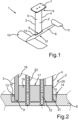
1 : Perspektivische Ansicht eines erfindungsgemäßen Hydrofoils zur Befestigung an einem Foilboard für das Kitesurfen; -
2 : Ansicht des Ausschnitts eines Längsschnitts durch den Verbindungsbereich zwischen Fuselage und Mast sowie -
3 : Ansicht des Ausschnitts eines Querschnitts durch den Verbindungsbereich zwischen Fuselage und Mast.
-
1 : Perspective view of a hydrofoil according to the invention for attachment to a foil board for kite surfing; -
2 : View of a detail of a longitudinal section through the connection area between fuselage and mast as well as -
3 : View of a section of a cross section through the connection area between fuselage and mast.
In Gebrauchslage des Hydrofoils 1 erstreckt sich der Mast 2 ausgehend vom Halteelement 7 in vertikaler Richtung im Wasser. An dem dem oberen Ende 6 gegenüberliegenden Ende 9 des Mastes 2, dem Mastfuß, ist eine Fuselage 8 angeordnet und mithilfe von zwei in dieser Ansicht nicht dargestellten Schrauben am Mast 2 befestigt. Während des Gebrauchs ist die Längsrichtung der Fuselage 8 in Fahrt- bzw. Fortbewegungsrichtung ausgerichtet. Am vorderen Ende der Fuselage 8 ist ein Frontflügel 10, auch Frontwing genannt, an dem Fuselage 8 befestigt. Am hinteren Ende der Fuselage 8 ist ein Heckflügel 11 angeordnet.In the operating position of the hydrofoil 1, the
Ein derartiges Hydrofoil sorgt dafür, dass aufgrund von hydrodynamischen Kräften ein an dem Hydrofoil befestigtes Wassersportbrett bei Fahrt auf oder durch das Wasser nach oben bewegt und somit von der Wasseroberfläche abgehoben wird. Aufgrund dieser Bewegung wird die mit dem Wasser in Berührung befindliche Fläche erheblich verkleinert, sodass auch bei geringen Windstärken und/oder vergleichsweise kleinen Segel- oder Lenkdrachenflächen zum Teil beträchtliche Fahrgeschwindigkeiten mit dem Wassersportbrett erreicht werden können.Such a hydrofoil ensures that, due to hydrodynamic forces, a water sports board attached to the hydrofoil is moved upwards when driving on or through the water and is thus lifted off the water surface. Due to this movement, the area in contact with the water is significantly reduced, so that even with low wind speeds and/or ver Equally small sailing or stunt kite areas, considerable driving speeds can be achieved with the water sports board.
Das erfindungswesentliche technische Merkmal des erfindungsgemäß ausgeführten, in
Bei dem in
Hierbei ist der Mast 2 als Aluminiumstrangpressprofil ausgeführt und im Inneren teilweise hohl, wobei der Mast 2 in seinem Inneren zur Herstellung einer Schaubverbindung 12 über zwei sich in Längsrichtung des Masts 2 erstreckende rohrförmige Streben 22 verfügt, die jeweils ein Innengewinde aufweisen.The
In diese Innengewinde sind zur Befestigung der Fuselage 8 am Mast 2 jeweils Senkschrauben mit Innensechskant eingeschraubt.Countersunk screws with a hexagon socket are screwed into these internal threads to fasten the
Erfindungswesentlich ist, dass der Mast 2 in eine Adapteraufnahme 16 eingesteckt ist, wobei sich das untere Ende 9 des Masts 2 innerhalb einer Ausnehmung der Fuselage 8 und somit innerhalb der Fuselage 8 befindet. Eine Kraftübertragung zwischen Fuselage 8 und Mast 2 findet somit aufgrund der formschlüssigen Verbindung in diesem Bereich über eine vergleichsweise große Kontaktfläche zwischen Adapter 13 und Fuselage 8 statt.It is essential to the invention that the
Im Übrigen verfügt der Adapter 13 über eine Anschlussstruktur 16, die in das Innere des Masts 2 hineinragt und hier eine formschlüssige Verbindung mit den Innenwand 18 des Masts 2 herstellt, wobei ein Formschluss sowohl zwischen der Anschlussstruktur 16 und der Innenwand 18 des Masts 2 als auch zwischen der Anschlussstruktur 16 des Masts und den vertikal im Inneren des Masts 2 verlaufenden Streben 22 gebildet wird.In addition, the
Der Adapter 13 ist in einer Ausnehmung 14 der Fuselage 8 angeordnet, wobei sich ein Formschluss zwischen der Ausnehmung 14 und den Außenflächen des Adapters 13 ergibt. Die Außenflächen des Adapters 13 sind derart angeschrägt, dass der Adapter 13 an dem der Fuselage 8 zugewandten, unteren Ende über seinen kleinsten Durchmesser verfügt, während der Durchmesser in Richtung auf das der Oberseite der Fuselage 8 zugewandten Ende des Adapters 13 stetig ansteigt. Der Adapter 13 ist aus Kunststoff gefertigt, sodass kein direkter Kontakt zwischen dem Mast 2 und der Fuselage 8 besteht.The
Im Übrigen ist sowohl das untere Ende 9 des Masts 2 als auch die Ausnehmung 14 der Fuselage 8 durch den Adapter 13 sicher gegenüber der Umgebung, vor allem gegenüber dem Seewasser abgedichtet. Auf diese Weise wird sichergestellt, dass kein Wasser in einen Bereich, in dem die Schrauben der Schraubverbindung 12 im Inneren der Fuselage 8 aus der Fuselage 8 austreten, gelangen kann. Ferner sind die Schrauben mithilfe einer Anti-Seize-Paste gegenüber der Umgebung abgedichtet, sodass auch über den Bereich der Schraubenköpfe kein Seewasser in den Gewindebereich und damit einen Kontaktbereich unterschiedlicher Metalle eindringen kann. Dies ist insbesondere von Bedeutung, da für die Schraubverbindung üblicherweise Schrauben aus Edelstahl verwendet werden, während für die Fuselage 8 und/oder den Mast 2 bevorzugt ein aluminiumhaltiges Material verwendet wird.Moreover, both the
Ergänzend zeigt
Deutlich zu erkennen ist wiederum, dass mit Hilfe des Adapters 13 sowohl ein Formschluss zwischen der Fuselage 8 und dem Adapter 13 als auch zwischen dem Adapter 13 und dem Mast 2 hergestellt wird. Das untere Ende 9 des Masts 2, das sich innerhalb des Adapteraufnahme 16 des Adapters 13 befindet, wird so sicher innerhalb der Ausnehmung 14 der Fuselage 8 gehalten, sodass Kräfte und/oder Drehmomente direkt innerhalb der Fuselage 8 zwischen dem Mast 2 und der Fuselage 8 über den Adapter 13 übertragen werden. Erfindungswesentliche ist hierbei, dass vergleichsweise große Flächen geschaffen werden, über die eine Übertragung auftretender Kräfte und Drehmomente erfolgt, so das erhöhte Flächenlasten und Spannungen in einzelnen Bereichen ausgeschlossen werden.Again, it can be clearly seen that with the help of the adapter 13 a form fit between the
BezugszeichenlisteReference List
- 11
- Hydrofoilhydrofoil
- 22
- Mastmast
- 33
- Anströmkanteleading edge
- 44
- Abströmkantetrailing edge
- 55
- Seitenflächeside face
- 66
- oberes Mastendeupper end of the mast
- 77
- Halterholder
- 88th
- Fuselagefuselage
- 99
- unteres Mastendelower end of the mast
- 1010
- Frontflügelfront wing
- 1111
- Heckflügelrear wing
- 1212
- Schraubverbindungscrew connection
- 1313
- Adapteradapter
- 1414
- Ausnehmungrecess
- 1515
- Adapteraußenflächeadapter outer surface
- 1616
- Adapteraufnahmeadapter mount
- 1717
- Anschlussstrukturconnector structure
- 1818
- Innenwand des Mastsinner wall of the mast
- 1919
- Strukturelementstructural element
- 2020
- Klebeverbindungadhesive connection
- 2121
- Mastaußenflächemast outer surface
- 2222
- Strebestrut
Claims (21)
Applications Claiming Priority (2)
| Application Number | Priority Date | Filing Date | Title |
|---|---|---|---|
| DE202019103496.3 | 2019-06-25 | ||
| DE202019103496.3U DE202019103496U1 (en) | 2019-06-25 | 2019-06-25 | Hydrofoil for attachment to a water sports board |
Publications (2)
| Publication Number | Publication Date |
|---|---|
| DE102020116552A1 DE102020116552A1 (en) | 2020-12-31 |
| DE102020116552B4 true DE102020116552B4 (en) | 2023-08-31 |
Family
ID=68105158
Family Applications (2)
| Application Number | Title | Priority Date | Filing Date |
|---|---|---|---|
| DE202019103496.3U Active DE202019103496U1 (en) | 2019-06-25 | 2019-06-25 | Hydrofoil for attachment to a water sports board |
| DE102020116552.8A Active DE102020116552B4 (en) | 2019-06-25 | 2020-06-23 | Hydrofoil for attachment to a water sports board |
Family Applications Before (1)
| Application Number | Title | Priority Date | Filing Date |
|---|---|---|---|
| DE202019103496.3U Active DE202019103496U1 (en) | 2019-06-25 | 2019-06-25 | Hydrofoil for attachment to a water sports board |
Country Status (2)
| Country | Link |
|---|---|
| US (1) | US11345449B2 (en) |
| DE (2) | DE202019103496U1 (en) |
Families Citing this family (15)
| Publication number | Priority date | Publication date | Assignee | Title |
|---|---|---|---|---|
| US10597118B2 (en) | 2016-09-12 | 2020-03-24 | Kai Concepts, LLC | Watercraft device with hydrofoil and electric propeller system |
| DE102019126843A1 (en) * | 2019-10-07 | 2021-04-08 | Boards & More Gmbh | Foil arrangement |
| US11613331B2 (en) * | 2020-03-06 | 2023-03-28 | Bi-Thermal Aspen Earth, L.L.C. | Composite masts and mast-fuselage connection assemblies for hydrofoil sports boards |
| US12246811B2 (en) | 2020-04-22 | 2025-03-11 | Kai Concepts, LLC | Watercraft device with a handheld controller |
| DE102021102124A1 (en) | 2020-12-22 | 2022-06-23 | Boards & More Gmbh | Foil arrangement and water sports equipment |
| EP4267453A1 (en) * | 2020-12-22 | 2023-11-01 | Boards & More GmbH | Foil assembly and piece of aquatic sports equipment |
| US12263912B2 (en) | 2021-03-05 | 2025-04-01 | Bi-Thermal Aspen Earth, L.L.C. | Composite hydrofoil components and systems |
| US20230242218A1 (en) * | 2022-01-28 | 2023-08-03 | Beta Foils Corporation | Hydrofoiling board |
| US12552495B2 (en) * | 2022-05-09 | 2026-02-17 | Robert Martin Johnston | Modular hydrofoil system for watercraft |
| US20230391424A1 (en) * | 2022-06-03 | 2023-12-07 | Square One Distribution, Inc. | Attachable-and-releaseable (swappable) fin for sport board, and adjustable mast for foiling systems |
| WO2024173165A2 (en) | 2023-02-14 | 2024-08-22 | Kai Concepts, LLC | Watercraft device with a handheld controller |
| AT527112B1 (en) * | 2023-04-13 | 2025-06-15 | Creaglobe Gmbh | HYDROFOIL FOR A WATERCRAFT |
| WO2025024628A1 (en) * | 2023-07-25 | 2025-01-30 | Naiad Maritime Group, Inc. | Active bow foil for ship motion control |
| CN116767433B (en) * | 2023-07-28 | 2025-12-12 | 深圳市苇渡智能科技有限公司 | Power systems for hydrofoils and electric hydrofoils |
| WO2026015649A1 (en) * | 2024-07-09 | 2026-01-15 | Bader John M | Modular mast for hydrofoil |
Citations (5)
| Publication number | Priority date | Publication date | Assignee | Title |
|---|---|---|---|---|
| US20050266746A1 (en) | 2003-11-25 | 2005-12-01 | Murphy Michael J | Extruded strut, fuselage and front wing assembly for towable hydrofoil |
| US20150017850A1 (en) | 2013-03-14 | 2015-01-15 | Hydrofoiled, Inc. | Universal Hydrofoil Connector System and Method of Attachment |
| EP2939917B1 (en) | 2014-04-30 | 2017-03-01 | F One | Modular hydrofoil device |
| US20170355429A1 (en) | 2016-06-09 | 2017-12-14 | Adherend Innovations, LLC | Hydrofoil assembly for watersports and associated methods of manufacture |
| EP3461734A1 (en) | 2017-09-27 | 2019-04-03 | Boards & More GmbH | Foil arrangement |
-
2019
- 2019-06-25 DE DE202019103496.3U patent/DE202019103496U1/en active Active
-
2020
- 2020-06-23 DE DE102020116552.8A patent/DE102020116552B4/en active Active
- 2020-06-24 US US16/911,045 patent/US11345449B2/en active Active
Patent Citations (5)
| Publication number | Priority date | Publication date | Assignee | Title |
|---|---|---|---|---|
| US20050266746A1 (en) | 2003-11-25 | 2005-12-01 | Murphy Michael J | Extruded strut, fuselage and front wing assembly for towable hydrofoil |
| US20150017850A1 (en) | 2013-03-14 | 2015-01-15 | Hydrofoiled, Inc. | Universal Hydrofoil Connector System and Method of Attachment |
| EP2939917B1 (en) | 2014-04-30 | 2017-03-01 | F One | Modular hydrofoil device |
| US20170355429A1 (en) | 2016-06-09 | 2017-12-14 | Adherend Innovations, LLC | Hydrofoil assembly for watersports and associated methods of manufacture |
| EP3461734A1 (en) | 2017-09-27 | 2019-04-03 | Boards & More GmbH | Foil arrangement |
Also Published As
| Publication number | Publication date |
|---|---|
| DE102020116552A1 (en) | 2020-12-31 |
| US20200407026A1 (en) | 2020-12-31 |
| DE202019103496U1 (en) | 2019-09-12 |
| US11345449B2 (en) | 2022-05-31 |
Similar Documents
| Publication | Publication Date | Title |
|---|---|---|
| DE102020116552B4 (en) | Hydrofoil for attachment to a water sports board | |
| DE102007019692B4 (en) | Wing-hull section of an airplane | |
| EP2154064B1 (en) | Rudder assembly for ships with high speeds with a cavitation reducing, twisted, in particular floating rudder | |
| DE202007015941U1 (en) | Oars for ships | |
| DE102018124323A1 (en) | Hydrofoil | |
| EP3461734B1 (en) | Foil arrangement | |
| EP2060483A1 (en) | High-performance rudder for ships | |
| DE102021119503A1 (en) | Attachment system for attaching a hydrofoil to a water sports board | |
| DE102009024845A1 (en) | propeller | |
| DE3043851A1 (en) | SAILING BOARD | |
| DE102013204033A1 (en) | Watercraft, in particular container or towboat | |
| DE602004000372T2 (en) | Device for a hole in a plate and so decorated plate | |
| EP4034456B1 (en) | Foil assembly | |
| DE4304158A1 (en) | Buoyancy fin | |
| AT527112B1 (en) | HYDROFOIL FOR A WATERCRAFT | |
| DE102019126843A1 (en) | Foil arrangement | |
| DE102024102216B3 (en) | Method for mounting a spoiler module on a body shell of a motor vehicle, body shell and motor vehicle | |
| DE3321219A1 (en) | Wind-driven vessel with a sailboard | |
| DE683298C (en) | Hull with buoyancy surfaces | |
| WO2026033246A1 (en) | Fastening system for fastening a hydrofoil to a water-sports board | |
| DE202007017450U1 (en) | High efficiency rudder for ships | |
| DE102005015338B4 (en) | Fin connection | |
| DE202015007384U1 (en) | Water sports equipment | |
| DE3112152A1 (en) | SWORD FOR A WATER VEHICLE | |
| DE102021001355A1 (en) | Arrangement for slidably positioning a fin in a fin box |
Legal Events
| Date | Code | Title | Description |
|---|---|---|---|
| R012 | Request for examination validly filed | ||
| R123 | Application deemed withdrawn due to non-payment of filing fee | ||
| R073 | Re-establishment requested | ||
| R074 | Re-establishment allowed | ||
| R016 | Response to examination communication | ||
| R018 | Grant decision by examination section/examining division | ||
| R020 | Patent grant now final |