DE102019212552B4 - Device for releasing, partially releasing and closing a flow opening, cooling device - Google Patents
Device for releasing, partially releasing and closing a flow opening, cooling device Download PDFInfo
- Publication number
- DE102019212552B4 DE102019212552B4 DE102019212552.2A DE102019212552A DE102019212552B4 DE 102019212552 B4 DE102019212552 B4 DE 102019212552B4 DE 102019212552 A DE102019212552 A DE 102019212552A DE 102019212552 B4 DE102019212552 B4 DE 102019212552B4
- Authority
- DE
- Germany
- Prior art keywords
- cable
- winch
- drive shaft
- cable winch
- component
- Prior art date
- Legal status (The legal status is an assumption and is not a legal conclusion. Google has not performed a legal analysis and makes no representation as to the accuracy of the status listed.)
- Active
Links
- 238000001816 cooling Methods 0.000 title claims description 16
- 238000005096 rolling process Methods 0.000 claims abstract description 4
- 238000004804 winding Methods 0.000 claims description 11
- 230000000903 blocking effect Effects 0.000 claims description 5
- 230000007257 malfunction Effects 0.000 claims description 5
- 239000002826 coolant Substances 0.000 claims description 4
- 238000006073 displacement reaction Methods 0.000 claims description 4
- 238000012544 monitoring process Methods 0.000 claims description 4
- 238000011144 upstream manufacturing Methods 0.000 claims description 3
- 238000004378 air conditioning Methods 0.000 description 5
- XLYOFNOQVPJJNP-UHFFFAOYSA-N water Substances O XLYOFNOQVPJJNP-UHFFFAOYSA-N 0.000 description 3
- 230000005540 biological transmission Effects 0.000 description 2
- 239000000498 cooling water Substances 0.000 description 2
- 238000007373 indentation Methods 0.000 description 2
- 239000000463 material Substances 0.000 description 2
- 229910000831 Steel Inorganic materials 0.000 description 1
- 230000004308 accommodation Effects 0.000 description 1
- 238000006243 chemical reaction Methods 0.000 description 1
- 238000001514 detection method Methods 0.000 description 1
- 230000000694 effects Effects 0.000 description 1
- 238000005259 measurement Methods 0.000 description 1
- 239000002184 metal Substances 0.000 description 1
- 230000002093 peripheral effect Effects 0.000 description 1
- 230000036316 preload Effects 0.000 description 1
- 239000010959 steel Substances 0.000 description 1
- 239000004753 textile Substances 0.000 description 1
Images
Classifications
-
- B—PERFORMING OPERATIONS; TRANSPORTING
- B60—VEHICLES IN GENERAL
- B60K—ARRANGEMENT OR MOUNTING OF PROPULSION UNITS OR OF TRANSMISSIONS IN VEHICLES; ARRANGEMENT OR MOUNTING OF PLURAL DIVERSE PRIME-MOVERS IN VEHICLES; AUXILIARY DRIVES FOR VEHICLES; INSTRUMENTATION OR DASHBOARDS FOR VEHICLES; ARRANGEMENTS IN CONNECTION WITH COOLING, AIR INTAKE, GAS EXHAUST OR FUEL SUPPLY OF PROPULSION UNITS IN VEHICLES
- B60K11/00—Arrangement in connection with cooling of propulsion units
- B60K11/08—Air inlets for cooling; Shutters or blinds therefor
- B60K11/085—Air inlets for cooling; Shutters or blinds therefor with adjustable shutters or blinds
-
- Y—GENERAL TAGGING OF NEW TECHNOLOGICAL DEVELOPMENTS; GENERAL TAGGING OF CROSS-SECTIONAL TECHNOLOGIES SPANNING OVER SEVERAL SECTIONS OF THE IPC; TECHNICAL SUBJECTS COVERED BY FORMER USPC CROSS-REFERENCE ART COLLECTIONS [XRACs] AND DIGESTS
- Y02—TECHNOLOGIES OR APPLICATIONS FOR MITIGATION OR ADAPTATION AGAINST CLIMATE CHANGE
- Y02T—CLIMATE CHANGE MITIGATION TECHNOLOGIES RELATED TO TRANSPORTATION
- Y02T10/00—Road transport of goods or passengers
- Y02T10/80—Technologies aiming to reduce greenhouse gasses emissions common to all road transportation technologies
- Y02T10/88—Optimized components or subsystems, e.g. lighting, actively controlled glasses
Landscapes
- Engineering & Computer Science (AREA)
- Chemical & Material Sciences (AREA)
- Combustion & Propulsion (AREA)
- Transportation (AREA)
- Mechanical Engineering (AREA)
- Power-Operated Mechanisms For Wings (AREA)
Abstract
Die Erfindung betrifft eine Vorrichtung (7) zum Freigeben, teilweise Freigeben und Verschließen einer Durchströmungsöffnung (9), mit einem Trägerrahmen, der die Durchströmungsöffnung (9) aufweist, und mit zumindest einem verlagerbaren Bauteil, mit einer dem Bauteil zu dessen Verlagerung zugeordneten Aktuatoreinrichtung (15), die eine drehbar gelagerte Antriebswelle (12), eine auf der Antriebswelle (12) drehfest angeordnete Seilwinde (19) und ein an der Seilwinde (19) einendig befestigtes Zugseil (18) aufweist, das anderendig an dem Bauteil befestigt ist und durch zumindest eine Umlenkrolle (21) zu dem Bauteil geführt ist. Es ist vorgesehen, dass das Bauteil ein Rollo (10) ist, das einendig an der Antriebswelle (12) zum Auf- und Abrollen und anderendig an dem Zugseil (18) befestigt ist, wobei die Seilwinde (19) kegelförmig ausgebildet ist.
Description
Die Erfindung betrifft eine Vorrichtung zum Freigeben, teilweise Freigeben und Verschließen einer Durchströmungsöffnung, mit einem Trägerrahmen, der die Durchströmungsöffnung aufweist, mit zumindest einem an dem Trägerrahmen verlagerbaren Bauteil, mit einer dem Bauteil zu dessen Verlagerung zugeordneten Aktuatoreinrichtung, die eine drehbar gelagerte Antriebswelle, eine auf der Antriebswelle drehfest angeordnete Seilwinde und ein an der Seilwinde einendig befestigtes Zugseil aufweist, das anderendig an dem Bauteil befestigt ist und durch zumindest eine Umlenkrolle zu dem Bauteil geführt ist.The invention relates to a device for releasing, partially releasing and closing a through-flow opening, with a support frame which has the through-flow opening, with at least one component that can be displaced on the support frame, with an actuator device assigned to the component for its displacement, which has a rotatably mounted drive shaft, a on the drive shaft non-rotatably arranged cable winch and a cable winch fixed at one end, which is fixed at the other end to the component and is guided by at least one deflection roller to the component.
Weiterhin betrifft die Erfindung eine Kühleinrichtung für ein Frontend eines Kraftfahrzeugs, mit zumindest einem Wärmetauscher, der eine Vielzahl von luftumströmbaren Kühlmittelkanälen aufweist, und mit einer dem Wärmetauscher vorgeschalteten Vorrichtung zum Freigeben, teilweise Freigeben und Verschließen einer Durchströmungsöffnung zu dem Wärmetauscher, die einen Trägerrahmen mit der Durchströmungsöffnung und zumindest ein an dem Trägerrahmen beweglich gelagertes Bauteil zum Freigeben, teilweise Freigeben und Verschließen der Durchströmungsöffnung aufweist. Die Vorrichtung ist dabei wie vorstehend beschrieben ausgebildet.Furthermore, the invention relates to a cooling device for a front end of a motor vehicle, with at least one heat exchanger, which has a multiplicity of coolant ducts around which air can flow, and with a device connected upstream of the heat exchanger for releasing, partially releasing and closing a flow opening to the heat exchanger, which has a support frame with the Has through-flow opening and at least one component movably mounted on the support frame for releasing, partially releasing and closing the through-flow opening. The device is designed as described above.
Vorrichtungen der eingangs genannten Art sind aus dem Stand der Technik bekannt. So beschreibt beispielsweise die Offenlegungsschrift
Der Erfindung liegt die Aufgabe zugrunde, eine verbesserte Vorrichtung zu schaffen, welche ein einfaches und sicheres Betätigen des Bauteils mittels des Zugseils erlaubt und insbesondere eine Zwangsführung für das Bauteil durch das Zugseil bietet, sodass sich das Bauteil nicht unabhängig von dem Zugseil bewegen kann.The object of the invention is to create an improved device that allows the component to be actuated easily and safely by means of the traction cable and, in particular, offers forced guidance for the component through the traction cable, so that the component cannot move independently of the traction cable.
Erfindungsgemäß ist hierzu vorgesehen, dass das Bauteil ein Rollo ist, das einendig an der Antriebswelle zum Auf- und Abrollen, auf beziehungsweise von der Antriebswelle, und anderendig an dem Zugseil befestigt ist, wobei die Seilwinde im Längsschnitt kegelförmig ausgebildet ist. Das Bauteil ist also ein auf- und abrollbares Rollo. Dadurch, dass das Bauteil beziehungsweise das Rollo anderendig mit dem Zugseil verbunden ist, ergibt sich, dass das Rollo einendig fest mit der Antriebswelle und anderendig fest mit der auf der Antriebswelle angeordneten Seilwinde verbunden ist, wodurch bei einer Bewegung der Antriebswelle beide Enden des Rollos mit der Seilwinde beziehungsweise dem Zugseil gekoppelt sind, sodass abhängig von der Stellung des Zugseils oder der Drehstellung der Antriebswelle in jeder Stellung die Position des Bauteils bestimmbar ist. Ein Bewegen des Rollos unabhängig von einer Bewegung des Zugseils ist nicht möglich. Wird nunmehr die Aktuatoreinrichtung für einen funktionsfreien Betrieb überwacht, so ist schnell feststellbar, ob ein Seilriss vorliegt oder nicht, weil in beide Betätigungsrichtungen bei fehlerfreiem Zugseil eine Reaktion an dem Rollo festzustellen ist. Durch die konische beziehungsweise kegelförmige Ausbildung der Seilwinde wird erreicht, dass das Zugseil auf einen sich verändernden Radius aufgerollt wird. Dadurch wird beispielsweise sichergestellt oder zumindest ermöglicht, dass das Zugseil stets eine Zugkraft auf das Rollo ausübt und nicht erschlaffen kann, wenn beispielsweise das Rollo schneller abgerollt als das Zugseil aufgerollt wird, wie es bei einer zylinderförmigen Seilwinde der Fall wäre. Damit ist durch die konische Form gewährleistet, dass das Zugseil unabhängig von der Stellung des Rollos stets auf Zug gespannt ist.According to the invention, the component is a roller blind, which is attached at one end to the drive shaft for rolling up and down, onto or off the drive shaft, and at the other end to the traction cable, with the cable winch being conical in longitudinal section. The component is therefore a roller blind that can be rolled up and down. The fact that the component or the roller blind is connected to the pull cable at the other end means that the roller blind is firmly connected at one end to the drive shaft and at the other end to the cable winch arranged on the drive shaft, which means that when the drive shaft moves, both ends of the roller blind the cable winch or the traction cable are coupled, so that the position of the component can be determined in any position depending on the position of the traction cable or the rotational position of the drive shaft. It is not possible to move the roller blind independently of the movement of the pull cord. If the actuator device is now monitored for function-free operation, it can be quickly determined whether there is a cable break or not, because a reaction on the roller blind can be determined in both directions of actuation with a fault-free pull cable. The conical or conical design of the cable winch ensures that the traction cable is rolled up to a changing radius. This ensures, for example, or at least enables, that the pull cable always exerts a pulling force on the blind and cannot slacken if, for example, the blind is unrolled faster than the pull cable is rolled up, as would be the case with a cylindrical cable winch. The conical shape ensures that the pull cable is always under tension, regardless of the position of the blind.
Gemäß einer bevorzugten Weiterbildung der Erfindung ist ein Kegelwinkel der Seilwinde abhängig von einem Wickelradius und einer Wickelhöhe des Rollos auf der Antriebswelle derart gewählt, dass das Zugseil stets auf Zug gespannt, insbesondere zumindest im Wesentlichen stets gleich gespannt ist. Wird der Wickelradius und die Wickelhöhe des Rollos berücksichtigt bei der Bestimmung des Kegelwickels ist es damit möglich, den oben genannten Effekt einfach zu gewährleisten. Die Wickelhöhe des Rollos ergibt sich dabei aus der Wandstärke des Rollos und der Wickelradius aus der Anzahl der auf der Antriebswelle bereits befindlichen Wicklungen des Rollos. Dabei wird der Kegelwinkel insbesondere auch in Abhängigkeit von einem Durchmesser des Zugseils gewählt, um bei einem Aufrollen des Rollos ein vorteilhaftes Abrollen des Zugseils zum Gleichhalten der Zugkraft beziehungsweise -spannung zu ermöglichen.According to a preferred development of the invention, a cone angle of the cable winch is selected depending on a winding radius and a winding height of the roller blind on the drive shaft such that the pull cable is always tensioned, in particular at least essentially always the same tension. If the winding radius and the winding height of the roller blind are taken into account when determining the cone winding, it is possible to achieve the above mentioned easy to ensure effect. The winding height of the roller blind results from the wall thickness of the roller blind and the winding radius from the number of windings of the roller blind already on the drive shaft. In this case, the cone angle is also selected in particular as a function of a diameter of the pull cable in order to enable an advantageous unrolling of the pull cable to keep the tensile force or tension constant when the roller blind is rolled up.
Besonders bevorzugt ist die Umlenkrolle federvorgespannt beweglich gelagert, sodass sie als Spannrolle für das Zugseil wirkt. Dadurch werden höhere Toleranzen für den Kegelwinkel ermöglicht, da Abweichungen durch ein federkraftbedingtes Verlagern der Umlenkrolle einfach ausgeglichen werden. Durch die Federvorspannung wird gewährleistet, dass das Zugseil zwischen dem Bauteil und der Seilwinde stets auf Zug gespannt ist.Particularly preferably, the deflection pulley is spring-loaded and movably mounted, so that it acts as a tensioning pulley for the traction cable. This enables higher tolerances for the cone angle, since deviations are easily compensated for by shifting the deflection roller due to spring force. The spring preload ensures that the traction cable between the component and the cable winch is always under tension.
Gemäß einer bevorzugten Weiterbildung der Erfindung ist der Seilwinde ein Gehäuse zugeordnet, wobei das Gehäuse zumindest im Querschnitt wenigstens einen Abschnitt aufweist, der sich in Längserstreckung der Seilwinde parallel zu der Seilwinde erstreckt. Das Gehäuse deckt somit die Seilwinde derart ab, dass es zumindest abschnittsweise der Kegelform der Seilwinde folgt, sodass der Abstand zwischen Gehäuse und Seilwinde über die Längserstreckung des Gehäuses gesehen konstant ist. Hierdurch ergibt sich der Vorteil, dass das Zugseil an der Seilwinde durch das Gehäuse vorteilhaft geführt ist, und insbesondere ein Überschlagen von benachbarten Zugseilabschnitten verhindert wird, wenn beispielsweise der Abstand zwischen Gehäuse und Seilwinde kleiner als der Durchmesser des Zugseils gewählt ist. Das Zugseil ist außerdem in dem Gehäuse sicher vor äußeren Einflüssen geschützt, sodass beispielsweise auch eine unberechtigte Manipulation der Vorrichtung verhindert wird.According to a preferred development of the invention, the cable winch is assigned a housing, the housing having at least one section, at least in cross section, which extends parallel to the cable winch in the longitudinal extension of the cable winch. The housing thus covers the cable winch in such a way that it follows the conical shape of the cable winch at least in sections, so that the distance between the housing and cable winch is constant when viewed over the longitudinal extent of the housing. This has the advantage that the traction cable on the cable winch is advantageously guided through the housing and, in particular, overturning of adjacent traction cable sections is prevented if, for example, the distance between the housing and cable winch is selected to be smaller than the diameter of the traction cable. The traction cable is also securely protected from external influences in the housing, so that, for example, unauthorized manipulation of the device is also prevented.
Besonders bevorzugt weist die Seilwinde eine nutförmige Vertiefung zur Aufnahme eines Seilabschnitts des Zugseils auf, die sich gewindeförmig entlang des Außenumfangs der Seilwinde erstreckt, sodass das Zugseil entlang der Vertiefung auf der Seilwinde aufrollbar ist. Durch die nutförmige Vertiefung wird das Zugseil beim Aufrollen gezielt entlang der Seilwinde geführt, wodurch das Zugseil im aufgerollten Zustand stets den gleichen Verlauf an der Seilwinde aufweist, wodurch sichergestellt wird, dass die Position des Bauteils mit der Drehstellung und Anzahl der Umdrehungen der Antriebswelle beziehungsweise Seilwinde erwartungsgemäß korrespondiert. Durch die nutförmige Vertiefung wird außerdem ein Überschlagen benachbarter Zugseilabschnitte zumindest weitestgehend verhindert.The cable winch particularly preferably has a groove-shaped recess for receiving a cable section of the traction cable, which extends in the form of a thread along the outer circumference of the cable winch, so that the traction cable can be rolled up on the cable winch along the recess. Due to the groove-shaped indentation, the traction cable is guided specifically along the cable winch when it is being rolled up, which means that the traction cable always runs the same way on the cable winch when it is rolled up, which ensures that the position of the component corresponds to the rotational position and number of revolutions of the drive shaft or cable winch corresponds as expected. The groove-shaped indentation also prevents neighboring sections of the traction cable from overturning, at least as far as possible.
Vorzugsweise ist ein radialer Abstand zwischen der Seilwinde und dem Gehäuse im Bereich der Vertiefung größer als ein Durchmesser des Zugseils und ein Abstand zwischen dem Außenumfang der Seilwinde, also axial beabstandet zu der Vertiefung, und dem Gehäuse kleiner als der Durchmesser des Zugseils. Dadurch ist gewährleistet, dass das Zugseil sicher in der nutförmigen Vertiefung geführt ist und nicht beispielsweise einen Gewindegang überspringen kann. Alternativ weist die Seilwinde eine durchgehende Außenumfangsfläche auf, und das Gehäuse weist einen radialen Abstand zu dem Außenumfang auf, der nur geringfügig größer als der Durchmesser des Zugseils ist, sodass auch hier ein Überschlagen benachbarter Zugseilabschnitte unmöglich ist. In beiden Fällen wird gewährleistet, dass dann, wenn beispielsweise aufgrund eines Zugspannungsverlusts ein ungeordnetes Aufrollen des Zugseils erfolgt, bei welchem ein Zugseilabschnitt einen benachbarten Zugseilabschnitt oder eine zwischen zwei nutförmigen Vertiefungen liegende Erhebung überschlägt, das Zugseil zwischen Gehäuse und Seilwinde verklemmt und dadurch die Seilwinde blockiert. Ein Überschlagen des Zugseils kann nur dann auftreten, wenn die üblicherweise vorhandene Zugseilspannung wegfällt. Dies ist beispielsweise dann der Fall, wenn das Zugseil reißen und damit die Verbindung zwischen Seilwinde und dem freien Rolloende lösen sollte. Durch die fehlende Zugspannung kann das Zugseil ungeordnet auf die Seilwinde aufgerollt werden, wobei dann aufgrund eines Überschlags ein Blockieren der Aktuatoreinrichtung durch das vorteilhafte Gehäuse herbeigeführt wird. Diese Blockade ist durch eine einfache Funktionsüberwachung der Aktuatoreinrichtung, insbesondere eines Elektromotors der Aktuatoreinrichtung feststellbar, sodass zeitnah insbesondere eine Beschädigung des Zugseils feststellbar ist.A radial distance between the cable winch and the housing in the area of the depression is preferably greater than a diameter of the traction cable and a distance between the outer circumference of the cable winch, i.e. axially spaced from the depression, and the housing is smaller than the diameter of the traction cable. This ensures that the traction cable is guided securely in the groove-shaped recess and cannot, for example, skip a thread. Alternatively, the cable winch has a continuous outer peripheral surface, and the housing has a radial distance from the outer circumference that is only slightly larger than the diameter of the traction cable, so that overturning adjacent traction cable sections is also impossible here. In both cases, it is ensured that if, for example, due to a loss of tension, the traction cable is rolled up in a disorderly manner, in which case a traction cable section overturns an adjacent traction cable section or an elevation lying between two groove-shaped depressions, the traction cable jams between the housing and the cable winch, thereby blocking the cable winch . Overturning of the traction cable can only occur if the traction cable tension that is usually present is lost. This is the case, for example, if the pull cable breaks and the connection between the cable winch and the free end of the roller blind should loosen. Due to the lack of tension, the traction cable can be rolled up onto the cable winch in a disorderly manner, with the actuator device then being blocked by the advantageous housing due to a rollover. This blockage can be detected by simply monitoring the function of the actuator device, in particular an electric motor of the actuator device, so that damage to the traction cable in particular can be detected promptly.
Weiterhin ist bevorzugt vorgesehen, dass die Aktuatoreinrichtung den oben bereits erwähnten Elektromotor aufweist, der zum Antreiben der Antriebswelle mit der Antriebswelle gekoppelt ist. Durch Überwachen von Stromfluss und/oder Spannungsverlauf des Elektromotors ist ein Blockieren des Elektromotors aufgrund eines Zugseil-Überschlags, wie obenstehend beschrieben, einfach und zeitnah feststellbar. Der Elektromotor ist dabei entweder direkt oder durch ein Getriebe, insbesondere Übersetzungsgetriebe, mit der Antriebswelle gekoppelt.Furthermore, it is preferably provided that the actuator device has the above-mentioned electric motor, which is coupled to the drive shaft to drive the drive shaft. By monitoring the flow of current and/or the course of the voltage in the electric motor, a blocking of the electric motor due to a haul rope rollover, as described above, can be detected easily and promptly. The electric motor is coupled to the drive shaft either directly or through a gear, in particular a transmission gear.
Weiterhin ist dem Elektromotor bevorzugt eine Sensoreinrichtung zum Überwachen des Elektromotors auf zumindest eine Fehlfunktion zugeordnet. Insbesondere weist die Sensoreinrichtung wenigstens ein Stromsensor und/oder wenigstens einen Spannungssensor auf, um den Betriebsstrom und/oder die Betriebsspannung des Elektromotors zu erfassen und zu überwachen. Nimmt beispielsweise der erfasste Betriebsstrom unerwartet zu, so wird festgestellt, dass der Elektromotor beziehungsweise die Aktuatoreinrichtung blockiert ist und ein Seilriss vorliegen muss.Furthermore, the electric motor is preferably assigned a sensor device for monitoring the electric motor for at least one malfunction. In particular, the sensor device has at least one current sensor and/or at least one voltage sensor in order to detect and monitor the operating current and/or the operating voltage of the electric motor. Takes example If the detected operating current is unexpected, it is determined that the electric motor or the actuator device is blocked and there must be a broken cable.
Bevorzugt ist daher die Sensoreinrichtung dazu ausgebildet, ein Blockieren der Antriebswelle als Fehlfunktion zu erfassen. Dadurch ist auf vorteilhafte Weise ein Seilriss erkennbar, wie obenstehend beschriebenThe sensor device is therefore preferably designed to detect a blocking of the drive shaft as a malfunction. As a result, a rope tear can be detected in an advantageous manner, as described above
Die erfindungsgemäße Kühleinrichtung mit den Merkmalen des Anspruchs 10 zeichnet sich durch die erfindungsgemäße Ausbildung der Vorrichtung aus. Es ergeben sich hierdurch die bereits genannten Vorteile.The cooling device according to the invention with the features of
Weitere Vorteile und bevorzugte Merkmale und Merkmalskombinationen ergeben sich insbesondere aus dem zuvor Beschriebenen sowie aus den Ansprüchen. Im Folgenden soll die Erfindung anhand der Zeichnungen näher erläutert werden. Dazu zeigen
-
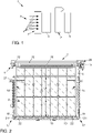
1 eine Kühleinrichtung für ein Frontend des Kraftfahrzeugs in einer vereinfachten Seitenansicht, -
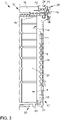
2 eine vorteilhafte Vorrichtung zum Freigeben, teilweise Freigeben und Verschließen einer Durchströmungsöffnung der Kühleinrichtung in einer Draufsicht, -
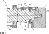
3 eine vergrößerte Teildarstellung der Vorrichtung in einer Draufsicht und -
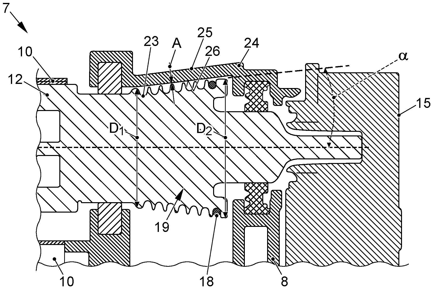
4 eine vereinfachte Schnittdarstellung der Vorrichtung.
-
1 a cooling device for a front end of the motor vehicle in a simplified side view, -
2 an advantageous device for releasing, partially releasing and closing a flow opening of the cooling device in a plan view, -
3 an enlarged partial representation of the device in a plan view and -
4 a simplified sectional view of the device.
Die Kühleinrichtung 1 weist gemäß dem vorliegenden Ausführungsbeispiel einen Wasserkühler 5 mit einer Vielzahl von mit Kühlwasser durchströmbaren Kühlwasserkanälen auf, einen Klimakondensator 6, der eine Vielzahl von Kühlmittelkanälen aufweist, durch welche ein Kühlmittel führbar ist, sowie eine Vorrichtung 7, die in Strömungsrichtung zwischen dem Wasserkühler 5 und dem Klimakondensator 6 angeordnet ist, und die dazu dient, den Luftstrom durch die Kühleinrichtung 1 zu beeinflussen. Optional weist die Kühleinrichtung 1 weiterhin einen ansteuerbaren Lüfter auf, der in Strömungsrichtung des Luftstroms durch die Kühleinrichtung bevorzugt hinter dem Klimakondensator 6 liegt und zumindest ein antreibbares Lüfterrad zum Erzeugen eines Luftstroms aufweist, für den Fall, dass Fahrtwind ausbleibt.According to the present exemplary embodiment, the cooling device 1 has a
Zum Betätigen des Rollos 10, also zum Verschieben des Rollos 10 von der in
Wie
Der Seilwinde 19 ist des Weiteren ein Gehäuse 24 zugeordnet, durch welches die Seilwinde zumindest abschnittsweise eingehaust ist. Das Gehäuse weise dabei einen Abschnitt 25 auf, der sich in Längserstreckung der Seilwinde 19 parallel zu der Seilwinde 19 erstreckt. Weil die Seilwinde 19 kegelförmig ausgebildet ist, erstreckt sich auch der Abschnitt 25 kegelförmig bezogen auf die Rotationsachse der Seilwinde 19. Dadurch ist gewährleistet, dass eine Innenseite 26 des Gehäuses 24 in dem Abschnitt 25 - in Längserstreckung der Seilwinde 19 gesehen - stets den gleichen radialen Abstand A zu dem Außenumfang der Seilwinde 19 aufweist. Der Radialabstand A ist dabei derart gewählt, dass er kleiner ist als der Durchmesser des Zugseils 18. Dadurch wird erreicht, dass das Zugseil 18 nicht zwischen der Seilwinde 19 und dem Gehäuse-Abschnitt 25 hindurchgezogen werden kann. Ein Aufrollen des Zugseils 18 ist somit nur in der Vertiefung 23 möglich.The
Wenn im Betrieb der Vorrichtung 7 beziehungsweise der Kühleinrichtung 1 aufgrund einer Fehlfunktion das Zugseil 18 seine Zugspannung verliert, beispielsweise weil es gerissen ist, würde ein ungeordnetes Aufrollen auf der Seilwinde 19 die Folge sein. Weil jedoch der Abstand A wie zuvor beschrieben gewählt ist, würde durch ein ungeordnetes Aufrollen das Zugseil 18 zwischen dem Außenumfang der Seilwinde 19 und dem Gehäuse 25 verklemmen und dadurch ein Weiterdrehen der Antriebswelle 12 oder der Seilwinde 19 erschweren oder verhindern.If the
Die Steuerungselektronik für den Aktuator kann das Blockieren der Antriebswelle 12 mittels einer einfachen und insbesondere in den Elektromotor integrierten Sensoreinrichtung 28, beispielsweise durch das Erfassen einer plötzlich ansteigenden Betriebsspannung oder einer Drehzahl der Antriebswelle 12, erkennen.The control electronics for the actuator can detect the blocking of the
Dadurch wird durch die vorteilhafte Ausbildung der Vorrichtung 7 erreicht, dass ein Fehlerzustand der Vorrichtung 7, insbesondere ein gerissenes oder beschädigtes Zugseil 18 einfach und sicher erkannt wird, ohne dass hierfür beispielsweise ein vollständiges Aufrollen und Abrollen des Rollos zur Wegerfassung notwendig ist.As a result, the advantageous design of the
BezugszeichenlisteReference List
- 11
- Kühleinrichtungcooling device
- 22
- Lufteinlassöffnungair intake opening
- 33
- Kraftfahrzeugmotor vehicle
- 44
- PfeilArrow
- 55
- Wasserkühlerwater cooler
- 66
- Klimakondensatorair conditioning condenser
- 77
- Vorrichtungcontraption
- 88th
- Trägerrahmencarrier frame
- 99
- Durchströmungsöffnungflow opening
- 1010
- Rolloroller blind
- 1111
- Oberseitetop
- 1212
- Antriebswelledrive shaft
- 1313
- PfeilArrow
- 1414
- Führungsnutguide groove
- 1515
- Aktuatoreinrichtungactuator device
- 1616
- EndeEnd
- 1717
- Seilzugeinrichtungcable device
- 1818
- Zugseilpull rope
- 1919
- Seilwindewinch
- 2020
- Unterseitebottom
- 2121
- Umlenkrollepulley
- 2222
- Vorspannfederbias spring
- 2323
- Vertiefungdeepening
- 2424
- GehäuseHousing
- 2525
- Abschnittsection
- 2626
- Innenseiteinside
- 2727
- Gitterstützstrukturlattice support structure
- 2828
- Sensoreinrichtungsensor device
Claims (10)
Priority Applications (1)
| Application Number | Priority Date | Filing Date | Title |
|---|---|---|---|
| DE102019212552.2A DE102019212552B4 (en) | 2019-08-22 | 2019-08-22 | Device for releasing, partially releasing and closing a flow opening, cooling device |
Applications Claiming Priority (1)
| Application Number | Priority Date | Filing Date | Title |
|---|---|---|---|
| DE102019212552.2A DE102019212552B4 (en) | 2019-08-22 | 2019-08-22 | Device for releasing, partially releasing and closing a flow opening, cooling device |
Publications (2)
| Publication Number | Publication Date |
|---|---|
| DE102019212552A1 DE102019212552A1 (en) | 2021-02-25 |
| DE102019212552B4 true DE102019212552B4 (en) | 2022-08-11 |
Family
ID=74495348
Family Applications (1)
| Application Number | Title | Priority Date | Filing Date |
|---|---|---|---|
| DE102019212552.2A Active DE102019212552B4 (en) | 2019-08-22 | 2019-08-22 | Device for releasing, partially releasing and closing a flow opening, cooling device |
Country Status (1)
| Country | Link |
|---|---|
| DE (1) | DE102019212552B4 (en) |
Citations (2)
| Publication number | Priority date | Publication date | Assignee | Title |
|---|---|---|---|---|
| EP3144182A1 (en) | 2015-08-20 | 2017-03-22 | SMP Deutschland GmbH | Cladding component for a vehicle |
| DE102016118555A1 (en) | 2016-09-29 | 2018-03-29 | Borgwarner Ludwigsburg Gmbh | Linear actuator for generating an adjustment movement in a motor vehicle |
-
2019
- 2019-08-22 DE DE102019212552.2A patent/DE102019212552B4/en active Active
Patent Citations (2)
| Publication number | Priority date | Publication date | Assignee | Title |
|---|---|---|---|---|
| EP3144182A1 (en) | 2015-08-20 | 2017-03-22 | SMP Deutschland GmbH | Cladding component for a vehicle |
| DE102016118555A1 (en) | 2016-09-29 | 2018-03-29 | Borgwarner Ludwigsburg Gmbh | Linear actuator for generating an adjustment movement in a motor vehicle |
Also Published As
| Publication number | Publication date |
|---|---|
| DE102019212552A1 (en) | 2021-02-25 |
Similar Documents
| Publication | Publication Date | Title |
|---|---|---|
| DE19618853C1 (en) | Motorised window drive with electronic anti-jamming protection e.g. for motor vehicles | |
| EP4294701B1 (en) | Steering column for a motor vehicle | |
| DE69824626T2 (en) | SOLDERABLE BRAKE FOR ROLLOS AND OTHER WINDOW COVERS | |
| DE102017211577A1 (en) | Automotive coolant heat exchanger with windable cover with variable winding speed and adapted traction means | |
| EP2683453B1 (en) | Drive unit for at least one traction means | |
| DE10245458A1 (en) | actuator | |
| DE102009041699B3 (en) | Curtain arrangement for an architectural opening | |
| DE102016220532A1 (en) | Steering column with energy absorption device for a motor vehicle | |
| EP4063312A1 (en) | Ejector for a forestry winch | |
| DE102019212552B4 (en) | Device for releasing, partially releasing and closing a flow opening, cooling device | |
| DE3907888C2 (en) | Vehicle seat belt retractor with tensioning device | |
| DE102019106828A1 (en) | Device for closing a motor vehicle cooling module | |
| EP1747923A2 (en) | Window roller blind with non-profiled thrust members | |
| EP2029382A1 (en) | Vehicle roof comprising a wind deflector | |
| DE102006035632B4 (en) | Roller blind arrangement for a vehicle roof | |
| EP3010613B1 (en) | Double-motor drive unit for traction means | |
| DE202017105164U1 (en) | steering column assembly | |
| EP1475282A1 (en) | Safety device and method of belt force limitation with such a device | |
| EP1736628B1 (en) | Guide for a sliding door | |
| DE102019105781B4 (en) | Device for covering a heat exchanger of a vehicle | |
| EP4074648A1 (en) | Ejector for a forestry winch | |
| DE29901034U1 (en) | Device for a roller shutter shaft | |
| DE60212029T2 (en) | Window lift with blocking of the driver and assembly process | |
| DE3600416A1 (en) | PASSIVE SAFETY BELT WITH A DRIVE DEVICE FOR MOVING AN END FITTING | |
| DE102009017654B4 (en) | Window shade, method of installing a window shade and method of making a window shade |
Legal Events
| Date | Code | Title | Description |
|---|---|---|---|
| R163 | Identified publications notified | ||
| R012 | Request for examination validly filed | ||
| R018 | Grant decision by examination section/examining division | ||
| R020 | Patent grant now final |