EP1736628B1 - Guide for a sliding door - Google Patents
Guide for a sliding door Download PDFInfo
- Publication number
- EP1736628B1 EP1736628B1 EP05405402A EP05405402A EP1736628B1 EP 1736628 B1 EP1736628 B1 EP 1736628B1 EP 05405402 A EP05405402 A EP 05405402A EP 05405402 A EP05405402 A EP 05405402A EP 1736628 B1 EP1736628 B1 EP 1736628B1
- Authority
- EP
- European Patent Office
- Prior art keywords
- sliding door
- tape
- door
- rail
- pulling
- Prior art date
- Legal status (The legal status is an assumption and is not a legal conclusion. Google has not performed a legal analysis and makes no representation as to the accuracy of the status listed.)
- Active
Links
Images

Classifications
-
- E—FIXED CONSTRUCTIONS
- E05—LOCKS; KEYS; WINDOW OR DOOR FITTINGS; SAFES
- E05D—HINGES OR SUSPENSION DEVICES FOR DOORS, WINDOWS OR WINGS
- E05D15/00—Suspension arrangements for wings
- E05D15/06—Suspension arrangements for wings for wings sliding horizontally more or less in their own plane
- E05D15/0621—Details, e.g. suspension or supporting guides
- E05D15/0626—Details, e.g. suspension or supporting guides for wings suspended at the top
-
- E—FIXED CONSTRUCTIONS
- E05—LOCKS; KEYS; WINDOW OR DOOR FITTINGS; SAFES
- E05Y—INDEXING SCHEME RELATING TO HINGES OR OTHER SUSPENSION DEVICES FOR DOORS, WINDOWS OR WINGS AND DEVICES FOR MOVING WINGS INTO OPEN OR CLOSED POSITION, CHECKS FOR WINGS AND WING FITTINGS NOT OTHERWISE PROVIDED FOR, CONCERNED WITH THE FUNCTIONING OF THE WING
- E05Y2201/00—Constructional elements; Accessories therefore
- E05Y2201/10—Covers; Housings
- E05Y2201/11—Covers
-
- E—FIXED CONSTRUCTIONS
- E05—LOCKS; KEYS; WINDOW OR DOOR FITTINGS; SAFES
- E05Y—INDEXING SCHEME RELATING TO HINGES OR OTHER SUSPENSION DEVICES FOR DOORS, WINDOWS OR WINGS AND DEVICES FOR MOVING WINGS INTO OPEN OR CLOSED POSITION, CHECKS FOR WINGS AND WING FITTINGS NOT OTHERWISE PROVIDED FOR, CONCERNED WITH THE FUNCTIONING OF THE WING
- E05Y2201/00—Constructional elements; Accessories therefore
- E05Y2201/60—Suspension or transmission members; Accessories therefore
- E05Y2201/622—Suspension or transmission members elements
- E05Y2201/684—Rails
-
- E—FIXED CONSTRUCTIONS
- E05—LOCKS; KEYS; WINDOW OR DOOR FITTINGS; SAFES
- E05Y—INDEXING SCHEME RELATING TO HINGES OR OTHER SUSPENSION DEVICES FOR DOORS, WINDOWS OR WINGS AND DEVICES FOR MOVING WINGS INTO OPEN OR CLOSED POSITION, CHECKS FOR WINGS AND WING FITTINGS NOT OTHERWISE PROVIDED FOR, CONCERNED WITH THE FUNCTIONING OF THE WING
- E05Y2600/00—Mounting or coupling arrangements for elements provided for in this subclass
- E05Y2600/10—Adjustable or movable
- E05Y2600/30—Adjustable or movable characterised by the type of motion
- E05Y2600/31—Linear motion
-
- E—FIXED CONSTRUCTIONS
- E05—LOCKS; KEYS; WINDOW OR DOOR FITTINGS; SAFES
- E05Y—INDEXING SCHEME RELATING TO HINGES OR OTHER SUSPENSION DEVICES FOR DOORS, WINDOWS OR WINGS AND DEVICES FOR MOVING WINGS INTO OPEN OR CLOSED POSITION, CHECKS FOR WINGS AND WING FITTINGS NOT OTHERWISE PROVIDED FOR, CONCERNED WITH THE FUNCTIONING OF THE WING
- E05Y2800/00—Details, accessories and auxiliary operations not otherwise provided for
- E05Y2800/34—Form stability
- E05Y2800/342—Deformable
-
- E—FIXED CONSTRUCTIONS
- E05—LOCKS; KEYS; WINDOW OR DOOR FITTINGS; SAFES
- E05Y—INDEXING SCHEME RELATING TO HINGES OR OTHER SUSPENSION DEVICES FOR DOORS, WINDOWS OR WINGS AND DEVICES FOR MOVING WINGS INTO OPEN OR CLOSED POSITION, CHECKS FOR WINGS AND WING FITTINGS NOT OTHERWISE PROVIDED FOR, CONCERNED WITH THE FUNCTIONING OF THE WING
- E05Y2900/00—Application of doors, windows, wings or fittings thereof
- E05Y2900/10—Application of doors, windows, wings or fittings thereof for buildings or parts thereof
- E05Y2900/13—Application of doors, windows, wings or fittings thereof for buildings or parts thereof characterised by the type of wing
- E05Y2900/132—Doors
Definitions
- the invention relates to the field of sliding doors in buildings, and more particularly to a guide for such a sliding door according to the preamble of claim 1.
- Such a guide is for example from the US 5,203,116 known. It describes a guide rail into which a paper strip is drawn when the door is opened and thus covers the inner regions of the rail. The paper strip is rolled up when closing the door on a roll. For this purpose, the winding on a torsion spring, which applies the necessary tension for winding the paper tape.
- the described type of cover is limited to smaller windows or doors in the living area.
- JP 2005 133298 discloses a guide for a sliding door with a band for covering the rail in a fully or partially opened state of the sliding door, wherein the band is introduced when opening the door in a covering position in the rail and when moving the door through a U shaped deflection slides.
- US 4,893,435 shows a door drive in which a toothed belt for moving the door revolves around a Umlenk leopardrad.
- the guide for a sliding door in a building has a rail with a band for covering the rail in a fully or partially opened state of the sliding door.
- the band is introduced when opening the sliding door in a covering position in the rail.
- the tape is not wound, but moved over a pulley.
- the deflection roller By means of the deflection roller, it is possible to hold the band outside the area to be covered of the sliding door in an extended state.
- the band is mostly stretched except for the areas where the band wraps around one or more pulleys.
- no additional essential space for winding the tape is needed.
- the band can be guided in a narrow area along the rail, so that increase the theoretically possible minimum dimensions of the rail only a few millimeters according to the thickness of the tape.
- the winding is delicate and involves the risk that the tape is not rolled up exactly when rolling up or unwinding, and tilted or jammed. This is particularly the case when a band of a stiff and thicker material such as metal or plastic is used. A certain stiffness is required so that the tape stays straight in the rail and does not sag.
- the invention is particularly suitable for use with a fire door, which may have lengths of about three to more than five meters. Usually they are open and are closed only in exceptional cases, so that a cover of the rail in the open state with respect to aesthetics and contamination of the rail is particularly advantageous. In an open state of the door so a portion of the rail is covered by the band in the open area of the sliding door
- the band is fastened at a first end to the sliding door and is deflected by at least one first stationary deflection roller in a direction opposite to a direction of displacement of the sliding door.
- the band is attached to a means for pulling the band, for example a toothed belt, a V-belt or a wire rope.
- the sliding direction of the sliding door is a linear movement. Depending on the direction of movement, it is referred to as the opening direction or closing direction of the sliding door.
- the band is deflected by the first deflection roller in the opposite direction (ie the closing direction of the door). The reverse applies when closing the sliding door.
- the means for pulling the tape on a second deflection roller which deflects the tape again in the direction of displacement of the sliding door, wherein the tape is attached to the second end of the sliding door. So it is the band pulled by the movement of the sliding door itself from the covering position in the area behind the first guide roller.
- the first diverting pulley is attached to a first end of the rail and the second diverting pulley is attached to a second end of the rail.
- this embodiment of the invention as well as the subsequent, means for tensioning the tape.
- the Means for clamping can be realized by a resilient suspension of at least one of the pulleys or by a resilient attachment between the sliding door and the band at least one end of the sliding door.
- the means for pulling the tape on a traction means such as a V-belt, a toothed belt or a wire rope, which traction means is attached to the second end of the belt, deflected by a second deflection roller in the direction of displacement of the sliding door is attached to the sliding door at the second end.
- a traction means such as a V-belt, a toothed belt or a wire rope, which traction means is attached to the second end of the belt, deflected by a second deflection roller in the direction of displacement of the sliding door is attached to the sliding door at the second end.
- the tape does not run completely around the pulleys from one end of the door to the other, but is about half replaced by the traction means.
- the traction means can be better used, inter alia, for other purposes such as driving or slowing down the door movement.
- the means for pulling the tape on a tensioning means which clamping means is attached to the second end of the belt and is rollable on a winding roll.
- the winding roll may be biased by a spring or driven by a motor.
- the tensioning means is, for example, a wire rope or another thin element which requires less space than the band during winding.
- the winding of the tape is replaced by a winding of the clamping means, wherein the tape itself is substantially stretched and unwound.
- the traction means respectively the tensioning means runs along the belt to a tümahen end of the belt.
- the band and the traction means and the clamping means are both attached to the door near the end of the first side of the sliding door. This can be at a motor driven door the force to close the door on the traction means or clamping means are transmitted without loading the belt.
- the traction means and the clamping means in the covered region of the rail are guided substantially parallel but spaced from each other. This prevents that the traction means respectively the clamping means in the covered area rest on the tape and thereby bulge down.
- the said spacing is achieved by the traction means or the tensioning means is guided via a first deflection roller to the first side of the sliding door, and the band is additionally guided by a third deflection roller further down along the covering position to the first side of the sliding door.
- the band is secured to the sliding door at a first end and is deflected by at least one first fixed pulley in a vertical direction with a weight attached to the second end of the band.
- the door construction also extends down the frame, but allows a simple construction - for doors whose opening is not much wider than high.
- the band is attached to both ends of the rail, so it is not circumferential.
- the belt is brought into the covering position via a pair of revolving deflection rollers attached to the sliding door.
- the band In the covering position, the band, as in the previous embodiments, rests on the running surfaces of the rail.
- the belt In the area above the door, the belt is in a higher storage position.
- the rail is preferably arranged above the sliding door, wherein the sliding door is suspended by a suspension in the rail slidably.
- the band is preferably made of fabric or plastic or metal or a series of linked rigid and flat members.
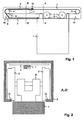
- FIGS. 1 to 3 show a first embodiment of the invention in different views.
- FIG. 1 shows a simplified side view of a sliding door 1, which is suspended by means of a suspension 9 with rollers 2 in a rail 8 horizontally displaceable. The rollers 2 roll on a tread or rolling surface 15 of the rail 8.
- a first end of a belt 3 is fixed, which is guided over a first guide roller 4 and a third guide roller 6 and so after the first guide roller 4 a Movement opposite to the direction of movement of the sliding door 1 performs.
- the belt 3 is connected at an attachment point 10 with a toothed belt 7, which toothed belt 7 is guided around a second deflection roller 5 again in the direction of movement of the sliding door 1 and attached at its end to the right side of the sliding door 1 is.
- the toothed belt 7 acts as a traction device, which pulls the band 3 around part of the orbit.
- the toothed belt 7 is guided along the belt 3 and substantially parallel thereto.
- the toothed belt 7 but, with the exception of the attachment point 10, not attached to the band 3.
- the toothed belt 7 is guided separately and above the belt 3.
- the toothed belt 7 is deflected by the first deflection roller 4 to a height above the rolling surface of the rail 8.
- the belt 3 is lowered by a third deflection roller 6 to the height of the rolling surface in the covering position and thus spaced from the toothed belt 7.
- the toothed belt 7 or one of the deflection rollers can be provided with a drive for moving the sliding door 1.
- FIG. 2 schematically shows a cross section AA 'in the region of the suspension 9.
- the band 3 In the upper part of the rail 8 is the space-saving arrangement of the opposite direction for suspension 9 moving belt 3 and the belt 7 visible.
- the band 3 In the in FIG. 1 drawn position of the sliding door 1, the band 3 is not visible in cross section. If the sliding door 1 is moved to the left, then the band 3 enters the position shown in dashed lines. In the FIG. 1 For reasons of illustration, the band 3 is thicker than the toothed belt 7.
- the Figures 2 and 3 show more typical proportions, with a toothed belt 7 with two rows of offset teeth and a height of about 1 to 2cm, and a band 3 with a height of several tenths of a millimeter (in a metal band) to a few millimeters (in a plastic band).
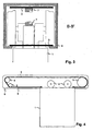
- FIG. 3 schematically shows a cross section BB 'in the region of the spaced guide of toothed belt 7 and 3 band.
- the band 3 is in the covered area on the rolling surfaces 15, respectively, is pulled over these surfaces 15.
- the moving in the same direction lower portion of the toothed belt 7 is spaced from the band 3.
- the belt 3 and the toothed belt 7 can be loose on each other.
- the rail 8 is not covered when the door 1 is closed - that is, shifted to the left - on the right side.
- the right-hand side can also be designed as a mirror image of the left-hand side, so that, for example, if the sliding door 1 has the function of a displaceable room divider, the rail 8 is always covered on both sides of the sliding door 1.
- FIG. 4 shows in principle an arrangement according to another embodiment of the invention.
- the band 3 itself is performed in the rail 8 completely encircling, and is attached at its second end to the right side of the sliding door 1.
- the band 3 also act on the right of the sliding door 1 as a cover.
- FIG. 5 shows in principle an arrangement according to another embodiment of the invention.
- the band is brought over the first guide roller 4 in a vertical course and is stretched by a weight 11.
- FIG. 6 shows in principle an arrangement according to another embodiment of the invention.
- the tape will be similar as in the FIG. 1 pulled by another element via an attachment point 10.
- the other element or clamping means here a wire rope 13 is not connected to the sliding door 1, but wound up on a winding roll 14.
- the fact that the clamping means has a substantially smaller cross-sectional area than the band 3, the problems mentioned above, which would be associated with the winding of the band 3, do not occur.
- FIG. 7 shows in principle an arrangement according to another embodiment of the invention.
- the band 3 at both ends fixed or possibly still sprung connected to the rail 8.
- the band 3 rests on the rolling surface 15 of the rail 8.
- the band 3 is conveyed over two follower pulleys 12 on the sliding door 1 upwards in runs from then on above the suspensions 9 in the upper region of the rail 8.
- the lower of the two follower pulleys 12 is mounted in a holder, which surrounds the vertically extending portion of the band 3 (viewed in cross-section of the rail) on the left and right. Any drive for pulling the sliding door 1 can also be performed left and right of this band section.
Abstract
Description
Die Erfindung bezieht sich auf das Gebiet der Schiebetüren in Gebäuden, und insbesondere auf eine Führung für eine solche Schiebetüre gemäss dem Oberbegriff des Patentanspruches 1.The invention relates to the field of sliding doors in buildings, and more particularly to a guide for such a sliding door according to the preamble of
Eine derartige Führung ist beispielsweise aus der
JP 2005 133298 offenbart eine Führung für eine Schiebetüre mit einem Band zur Abdeckung der Schiene in einem ganz oder teilweise geöffneten Zustand der Schiebetür, wobei das Band beim Öffnen der Türe in eine Abdeckposition in der Schiene eingebracht wird und beim Bewegen der Türe durch eine U-förmige Umlenkung gleitet. JP 2005 133298 discloses a guide for a sliding door with a band for covering the rail in a fully or partially opened state of the sliding door, wherein the band is introduced when opening the door in a covering position in the rail and when moving the door through a U shaped deflection slides.
US 4,893,435 zeigt einen Türantrieb, bei welchem ein Zahnriemen zur Bewegung der Türe um ein Umlenkzahnrad umläuft. US 4,893,435 shows a door drive in which a toothed belt for moving the door revolves around a Umlenkzahnrad.
Es ist deshalb Aufgabe der Erfindung, eine Führung für eine Schiebetür in einem Gebäude der eingangs genannten Art zu schaffen, welche eine Abdeckung der Führung auch bei grösseren Türen erlaubt.It is therefore an object of the invention to provide a guide for a sliding door in a building of the type mentioned, which allows a cover of the guide even with larger doors.
Diese Aufgabe löst eine Führung für eine Schiebetür in einem Gebäude mit den Merkmalen des Patentanspruches 1.This object is achieved by a guide for a sliding door in a building having the features of
Die Führung für eine Schiebetür in einem Gebäude weist eine Schiene mit einem Band zur Abdeckung der Schiene in einem ganz oder teilweise geöffneten Zustand der Schiebetür auf. Dabei wird das Band beim Öffnen der Schiebetür in eine Abdeckposition in der Schiene eingebracht. Beim Schliessen der Türe wird das Band nicht aufgewickelt, sondern über eine Umlenkrolle bewegt.The guide for a sliding door in a building has a rail with a band for covering the rail in a fully or partially opened state of the sliding door. In this case, the band is introduced when opening the sliding door in a covering position in the rail. When closing the door, the tape is not wound, but moved over a pulley.
Mittels der Umlenkrolle wird es möglich, das Band auch ausserhalb des abzudeckenden Bereiches der Schiebetür in einem gestreckten Zustand zuhalten. Das Band ist also grösstenteils gestreckt, mit Ausnahme der Bereiche, in welchen das Band eine oder mehrere Umlenkrollen umschlingt. Dadurch wird kein zusätzlicher wesentlicher Raum zum Aufwickeln des Bandes benötigt. Beispielsweise kann stattdessen das Band in einem schmalen Bereich entlang der Schiene geführt werden, so dass sich die theoretisch möglichen minimalen Abmessungen der Schiene nur um wenige Millimeter entsprechend der Dicke des Bandes erhöhen.By means of the deflection roller, it is possible to hold the band outside the area to be covered of the sliding door in an extended state. Thus, the band is mostly stretched except for the areas where the band wraps around one or more pulleys. As a result, no additional essential space for winding the tape is needed. For example, instead, the band can be guided in a narrow area along the rail, so that increase the theoretically possible minimum dimensions of the rail only a few millimeters according to the thickness of the tape.
Ferner wird es damit möglich, das Aufwickeln des Bandes zu vermeiden. Das Aufwickeln ist heikel und birgt die Gefahr, dass das Band beim Auf- oder Abwickeln nicht exakt (gerade) aufgerollt wird, und sich verkantet oder verklemmt. Dies ist insbesondere der Fall, wenn ein Band aus einem steifen und dickeren Material wie Metall oder Kunststoff verwendet wird. Eine gewisse Steifigkeit ist erforderlich, damit das Band in der Schiene gerade liegen bleibt und nicht durchhängt.It also makes it possible to avoid the winding of the tape. The winding is delicate and involves the risk that the tape is not rolled up exactly when rolling up or unwinding, and tilted or jammed. This is particularly the case when a band of a stiff and thicker material such as metal or plastic is used. A certain stiffness is required so that the tape stays straight in the rail and does not sag.
Ein solches Band würde beim Aufwickeln eine dicke Rolle ergeben, welche wiederum einen entsprechenden Platzbedarf ergibt. Je länger die Türe ist, desto grösser wäre der Raumbedarf für ein aufgewickeltes Band. Dadurch ist die Erfindung insbesondere für den Einsatz mit einer Brandschutztüre geeignet, die Längen von über drei bis über fünf Metern aufweisen können. In der Regel stehen sie offen und werden nur im Ausnahmefall geschlossen, so dass eine Abdeckung der Schiene im offenen Zustand bezüglich Ästhetik und Verschmutzung der Schiene besonders vorteilhaft ist. In einem offenen Zustand der Türe ist also im offenen Bereich der Schiebetür ein Bereich der Schiene durch das Band abgedecktSuch a band would result in a thick roll when winding, which in turn results in a corresponding space requirement. The longer the door is, the larger would be the space required for a wound tape. Thus, the invention is particularly suitable for use with a fire door, which may have lengths of about three to more than five meters. Usually they are open and are closed only in exceptional cases, so that a cover of the rail in the open state with respect to aesthetics and contamination of the rail is particularly advantageous. In an open state of the door so a portion of the rail is covered by the band in the open area of the sliding door
In einer bevorzugten Ausführungsform der Erfindung ist das Band an einem ersten Ende an der Schiebetür befestigt und wird durch mindestens eine erste feststehende Umlenkrolle in eine Gegenrichtung zu einer Verschiebungsrichtung der Schiebetür umgelenkt. An einem zweiten Ende, welches dem ersten Ende gegenüberliegt, ist das Band an einem Mittel zum Ziehen des Bandes befestigt, beispielsweise an einem Zahnriemen, einem Keilriemen oder einem Drahtseil. Die Verschiebungsrichtung der Schiebetür ist eine Linearbewegung. Je nach Richtung der Bewegung wird sie als Öffnungsrichtung oder Schliessrichtung der Schiebetüre bezeichnet. Bei Verschiebung der Schiebetüre in die Öffnungsrichtung wird das Band durch die erste Umlenkrolle in die entgegengesetzte Richtung (also der Schliessrichtung der Türe) umgelenkt. Das Umgekehrte gilt beim Schliessen der Schiebetüre.In a preferred embodiment of the invention, the band is fastened at a first end to the sliding door and is deflected by at least one first stationary deflection roller in a direction opposite to a direction of displacement of the sliding door. At a second end opposite the first end, the band is attached to a means for pulling the band, for example a toothed belt, a V-belt or a wire rope. The sliding direction of the sliding door is a linear movement. Depending on the direction of movement, it is referred to as the opening direction or closing direction of the sliding door. Upon displacement of the sliding door in the opening direction, the band is deflected by the first deflection roller in the opposite direction (ie the closing direction of the door). The reverse applies when closing the sliding door.
In einer weiteren bevorzugten Ausführungsform der Erfindung weist das Mittel zum Ziehen des Bandes eine zweite Umlenkrolle auf, welche das Band wieder in die Verschiebungsrichtung der Schiebetür umlenkt, wobei das Band am zweiten Ende an der Schiebetür befestigt ist. Es wird also das Band durch die Bewegung der Schiebetür selber aus der Abdeckposition in den Bereich hinter der ersten Umlenkrolle gezogen. Damit sind keine weiteren Mittel wie Federn oder Antriebe zum Zurückziehen des Bandes erforderlich. Die erste Umlenkrolle ist an einem ersten Ende der Schiene und die zweite Umlenkrolle an einem zweiten Ende der Schiene angebracht.In a further preferred embodiment of the invention, the means for pulling the tape on a second deflection roller, which deflects the tape again in the direction of displacement of the sliding door, wherein the tape is attached to the second end of the sliding door. So it is the band pulled by the movement of the sliding door itself from the covering position in the area behind the first guide roller. Thus, no further means such as springs or drives to retract the tape are required. The first diverting pulley is attached to a first end of the rail and the second diverting pulley is attached to a second end of the rail.
Vorzugsweise weist diese Ausführungsform der Erfindung, wie auch die nachfolgenden, Mittel zum Spannen des Bandes auf. Dadurch werden Längenschwankungen des umlaufenden Bandes respektive der Schiene ausgeglichen. Die Mittel zum Spannen können durch eine federnde Aufhängung mindestens einer der Umlenkrollen oder durch eine federnde Befestigung zwischen der Schiebetüre und dem Band an mindestens einem Ende der Schiebetüre realisiert sein.Preferably, this embodiment of the invention, as well as the subsequent, means for tensioning the tape. As a result, variations in length of the circulating belt or the rail are compensated. The Means for clamping can be realized by a resilient suspension of at least one of the pulleys or by a resilient attachment between the sliding door and the band at least one end of the sliding door.
In einer Variante zur eben beschriebenen Ausführungsform der Erfindung weist das Mittel zum Ziehen des Bandes ein Zugmittel wie beispielsweise einen Keilriemen, einen Zahnriemen oder ein Drahtseil auf, welches Zugmittel am zweiten Ende des Bandes befestigt ist, über eine zweite Umlenkrolle in die Verschiebungsrichtung der Schiebetür umgelenkt wird und am zweiten Ende an der Schiebetür befestigt ist. Im Gegensatz zur vorherigen Ausführungsform läuft also das Band nicht vollständig um die Umlenkrollen von einem Ende der Türe zum anderen, sondern ist ungefähr zur Hälfte durch das Zugmittel ersetzt. Dadurch kann das Zugmittel unter anderem besser für andere Zwecke wie für den Antrieb oder das Abbremsen der Türbewegung eingesetzt werden.In a variant of the just described embodiment of the invention, the means for pulling the tape on a traction means such as a V-belt, a toothed belt or a wire rope, which traction means is attached to the second end of the belt, deflected by a second deflection roller in the direction of displacement of the sliding door is attached to the sliding door at the second end. In contrast to the previous embodiment, therefore, the tape does not run completely around the pulleys from one end of the door to the other, but is about half replaced by the traction means. As a result, the traction means can be better used, inter alia, for other purposes such as driving or slowing down the door movement.
In einer anderen Variante zur vorherigen Ausführungsform der Erfindung weist das Mittel zum Ziehen des Bandes ein Spannmittel auf, welches Spannmittel am zweiten Ende des Bandes befestigt ist und an einer Wickelrolle aufrollbar ist. Die Wickelrolle kann durch eine Feder vorgespannt sein oder durch einen Motor angetrieben sein. Das Spannmittel ist beispielsweise ein Drahtseil oder ein anderes dünnes Element, welches beim Aufwickeln weniger Raum als das Band benötigt. Hier wird also das Aufwickeln des Bandes durch ein Aufwickeln des Spannmittels ersetzt, wobei das Band selber im wesentlichen gestreckt und unaufgewickelt bleibt.In another variant of the previous embodiment of the invention, the means for pulling the tape on a tensioning means, which clamping means is attached to the second end of the belt and is rollable on a winding roll. The winding roll may be biased by a spring or driven by a motor. The tensioning means is, for example, a wire rope or another thin element which requires less space than the band during winding. Here, therefore, the winding of the tape is replaced by a winding of the clamping means, wherein the tape itself is substantially stretched and unwound.
In einer weiteren bevorzugten Ausführungsform der Erfindung verläuft das Zugmittel respektive das Spannmittel dem Band entlang bis zu einem tümahen Ende des Bandes. Das heisst, dass das Zugmittel respektive das Spannmittel im wesentlichen parallel zum Band verlaufen und sich miteinander bewegen. Das Band und das Zugmittel respektive das Spannmittel sind beide am türnahen Ende an der ersten Seite der Schiebetür befestigt. Dadurch kann bei einer motorisch angetriebenen Türe die Kraft zum Schliessen der Türe über das Zugmittel oder Spannmittel übertragen werden, ohne das Band zu belasten. Vorzugsweise sind das Zugmittel und das Spannmittel im abgedeckten Bereich der Schiene im wesentlichen parallel aber von einander beabstandet geführt. Dadurch wird verhindert, dass das Zugmittel respektive das Spannmittel im abgedeckten Bereich auf dem Band aufliegen und dadurch nach unten ausbauchen.In a further preferred embodiment of the invention, the traction means respectively the tensioning means runs along the belt to a tümahen end of the belt. This means that the traction means and the tensioning means are substantially parallel to the belt and move together. The band and the traction means and the clamping means are both attached to the door near the end of the first side of the sliding door. This can be at a motor driven door the force to close the door on the traction means or clamping means are transmitted without loading the belt. Preferably, the traction means and the clamping means in the covered region of the rail are guided substantially parallel but spaced from each other. This prevents that the traction means respectively the clamping means in the covered area rest on the tape and thereby bulge down.
Vorzugsweise wird die genannte Beabstandung erreicht, indem das Zugmittel respektive das Spannmittel über eine erste Umlenkrolle zur ersten Seite der Schiebetür geführt wird, und das Band zusätzlich durch eine dritte Umlenkrolle weiter unten entlang der Abdeckposition zur ersten Seite der Schiebetür geführt wird.Preferably, the said spacing is achieved by the traction means or the tensioning means is guided via a first deflection roller to the first side of the sliding door, and the band is additionally guided by a third deflection roller further down along the covering position to the first side of the sliding door.
In einer anderen bevorzugten Ausführungsform der Erfindung ist das Band an einem ersten Ende an der Schiebetür befestigt und wird durch mindestens eine erste feststehende Umlenkrolle in eine vertikale Richtung umgelenkt, wobei ein Gewicht am zweiten Ende des Bandes befestigt ist. Damit erstreckt sich die Türkonstruktion auch entlang des Rahmens nach unten, erlaubt aber eine einfache Konstruktion - für Türen, deren Öffnung nicht wesentlich breiter als hoch ist.In another preferred embodiment of the invention, the band is secured to the sliding door at a first end and is deflected by at least one first fixed pulley in a vertical direction with a weight attached to the second end of the band. Thus, the door construction also extends down the frame, but allows a simple construction - for doors whose opening is not much wider than high.
In einer anderen bevorzugten Ausführungsform der Erfindung ist das Band an beiden Enden an der Schiene befestigt, ist also nicht umlaufend. Beim Öffnen der Schiebetür wird das Band über ein Paar von an der Schiebetür befestigten, mitlaufenden Umlenkrollen in die Abdeckposition gebracht. In der Abdeckposition liegt das Band, wie auch bei den bisherigen Ausführungsformen, auf den Laufflächen der Schiene auf. Im Bereich über der Türe befindet sich das Band in einer höheren Lagerposition. Durch eine Z- oder S-förmige Bewegung des Bandes um das Paar von mitlaufenden Umlenkrollen wird es beim Öffnen der Türe aus der Lagerposition in die Abdeckposition abgerollt.In another preferred embodiment of the invention, the band is attached to both ends of the rail, so it is not circumferential. When the sliding door is opened, the belt is brought into the covering position via a pair of revolving deflection rollers attached to the sliding door. In the covering position, the band, as in the previous embodiments, rests on the running surfaces of the rail. In the area above the door, the belt is in a higher storage position. By a Z- or S-shaped movement of the band around the pair of idler pulleys, it is unrolled from the storage position to the capping position upon opening the door.
Die Schiene ist vorzugsweise oberhalb der Schiebetür angeordnet, wobei die Schiebetür durch eine Aufhängung in der Schiene verschiebbar aufgehängt ist. Das Band besteht vorzugsweise aus Stoff oder Kunststoff oder Metall oder aus einer Folge von verketteten starren und flachen Gliedern.The rail is preferably arranged above the sliding door, wherein the sliding door is suspended by a suspension in the rail slidably. The band is preferably made of fabric or plastic or metal or a series of linked rigid and flat members.
In weiteren bevorzugten Variante der oben beschriebenen Ausführungsformen der Erfindung ist es das Band selber, das durch einen motorischen Antrieb oder Schwerkraftantrieb getrieben wird und die Türe zuzieht. Damit sind keine weiteren Mittel zur Kraftübertragung wie Drahtseile oder Zahnriemen nötig.In a further preferred variant of the embodiments of the invention described above, it is the belt itself, which is driven by a motor drive or gravity drive and pulls the door. Thus, no further means for power transmission such as wire ropes or timing belts are needed.
Weitere bevorzugte Ausführungsformen gehen aus den abhängigen Patentansprüchen hervor.Further preferred embodiments emerge from the dependent claims.
Im folgenden wird der Erfindungsgegenstand anhand von bevorzugten Ausführungsbeispielen, welche in den beiliegenden Zeichnungen dargestellt sind, näher erläutert. Es zeigen jeweils schematisch:
Figuren 1bis 3- eine erste Ausführungsform der Erfindung in verschiedenen Ansichten; und
Figuren 4bis 7- prinzipiell unterschiedliche Anordnungen gemäss weiteren Ausführungsformen der Erfindung.
- FIGS. 1 to 3
- a first embodiment of the invention in various views; and
- FIGS. 4 to 7
- in principle, different arrangements according to further embodiments of the invention.
Die in den Zeichnungen verwendeten Bezugszeichen und deren Bedeutung sind in der Bezugszeichenliste zusammengefasst aufgelistet. Grundsätzlich sind in den Figuren gleiche Teile mit gleichen Bezugszeichen versehen.The reference numerals used in the drawings and their meaning are listed in the list of reference numerals. Basically, the same parts are provided with the same reference numerals in the figures.
Vorzugsweise ist der Zahnriemen 7 entlang des Bandes 3 und im wesentlichen parallel zu diesem geführt. Dabei ist der Zahnriemen 7 aber, mit Ausnahme des Befestigungspunktes 10, nicht am Band 3 befestigt. Im Bereich der Abdeckung ist der Zahnriemen 7 separat und oberhalb des Bandes 3 geführt. Dazu wird der Zahnriemen 7 durch die erste Umlenkrolle 4 auf eine Höhe oberhalb der Rollfläche der Schiene 8 umgelenkt. Das Band 3 wird durch eine dritte Umlenkrolle 6 auf die Höhe der Rollfläche in die Abdeckposition heruntergeführt und so vom Zahnriemen 7 beabstandet. Der Zahnriemen 7 oder eine der Umlenkrollen können mit einem Antrieb zur Bewegung der Schiebetür 1 versehen sein.Preferably, the
In der Ausführungsform gemäss der
- 11
- Schiebetürsliding door
- 22
- Laufrollecaster
- 33
- Bandtape
- 44
- erste Umlenkrollefirst pulley
- 55
- zweite Umlenkrollesecond deflection roller
- 66
- dritte Umlenkrollethird pulley
- 77
- Zahnriementoothed belt
- 88th
- Schienerail
- 99
- Aufhängungsuspension
- 1010
- Befestigungspunktattachment point
- 1111
- GewichtWeight
- 1212
- mitlaufende Umlenkrollenfollower pulleys
- 1313
- DrahtseilWire rope
- 1414
- Wickelrollereel
- 1515
- Rollflächerolling surface
Claims (8)
- Guiding mechanism for a sliding door (1) in a building, comprising a rail (8) for guiding the sliding door (1) when it is displaced, with a tape (3) for covering the rail (8) in a completely or partially open condition of the sliding door (1), wherein the tape (3) is attached to the sliding door (1) at a first end and when opening the sliding door (1) is brought into a covering position in the rail (8), characterised in that the tape (3) by means of at least one first deflecting roller (4) is deflected into an opposite direction to a displacement direction of the sliding door (1), and at a second end is attached to a means (13, 14; 7; 1) for pulling the tape (3).
- Guiding mechanism for a sliding door (1) in accordance with claim 1, wherein the means for pulling the tape (3) comprises a second deflecting roller (5), which deflects the tape once again into the displacement direction of the sliding door (1), and the tape at the second end is attached to the sliding door (1).
- Guiding mechanism for a sliding door (1) in accordance with claim 1, wherein the means for pulling the tape (3) comprises a means for pulling (7), which means for pulling (7) is attached at the second end of the tape (3), by means of a second deflection roller (5) is deflected into the displacement direction of the sliding door (1) and at the second end is attached to the sliding door (1).
- Guiding mechanism for a sliding door (1) in accordance with claim 1, wherein the means for pulling the tape (3) comprises a tensioning means (13), which tensioning means (13) is attached to the second end of the tape (3) and is capable of being rolled-up on a winding roller (14).
- Guiding mechanism for a sliding door (1) in accordance with claim 3 or 4, wherein the means for pulling (7) or, respectively, the tensioning means (13) extends along the tape (3) up to an end close to the door, the tape (3) at its first end is attached to a first side of the sliding door (1), and the means for pulling (7) or, respectively, the tensioning means (13) at an end close to the door is also attached to the first side of the sliding door (1), and the means for pulling (7) or, respectively, the tensioning means (13) are guided in the covered zone of the rail (8) at a distance from one another.
- Guiding mechanism for a sliding door (1) in accordance with claim 5, wherein the means for pulling (7), respectively, the tensioning means (13) by the first deflection roller (4) are deflected to the first side of the sliding door (1), and the tape (3) by the first deflection roller (4) and additionally by a third deflection roller (6) is deflected to the first side of the sliding door (1) and into the covering position.
- Guiding mechanism for a sliding door (1) in accordance with one of the preceding claims, wherein the rail (8) is arranged above the sliding door (1) and the sliding door (1) by a suspension device (9) is suspended capable of being displaced in the rail (8).
- Guiding mechanism for a sliding door (1) in accordance with one of the preceding claims, wherein the tape (3) consists of cloth or plastic material or metal or of a sequence of interlinked rigid and flat links.
Priority Applications (2)
| Application Number | Priority Date | Filing Date | Title |
|---|---|---|---|
| AT05405402T ATE553274T1 (en) | 2005-06-24 | 2005-06-24 | GUIDE FOR A SLIDING DOOR |
| EP05405402A EP1736628B1 (en) | 2005-06-24 | 2005-06-24 | Guide for a sliding door |
Applications Claiming Priority (1)
| Application Number | Priority Date | Filing Date | Title |
|---|---|---|---|
| EP05405402A EP1736628B1 (en) | 2005-06-24 | 2005-06-24 | Guide for a sliding door |
Publications (2)
| Publication Number | Publication Date |
|---|---|
| EP1736628A1 EP1736628A1 (en) | 2006-12-27 |
| EP1736628B1 true EP1736628B1 (en) | 2012-04-11 |
Family
ID=35266897
Family Applications (1)
| Application Number | Title | Priority Date | Filing Date |
|---|---|---|---|
| EP05405402A Active EP1736628B1 (en) | 2005-06-24 | 2005-06-24 | Guide for a sliding door |
Country Status (2)
| Country | Link |
|---|---|
| EP (1) | EP1736628B1 (en) |
| AT (1) | ATE553274T1 (en) |
Families Citing this family (4)
| Publication number | Priority date | Publication date | Assignee | Title |
|---|---|---|---|---|
| DE102007006358A1 (en) * | 2007-02-08 | 2008-08-21 | Dura Automotive Body & Glass Systems Gmbh | Sliding door for a motor vehicle |
| DE102008008128A1 (en) * | 2008-02-08 | 2009-08-13 | GM Global Technology Operations, Inc., Detroit | Cover of guide parts of a motor vehicle sliding door |
| DE202010010233U1 (en) * | 2010-07-14 | 2011-11-14 | MACO Vermögensverwaltung GmbH | fitting device |
| ITVI20110266A1 (en) * | 2011-10-04 | 2013-04-05 | Axer S R L | SLIDING WINDOW COMPLETE WITH DISAPPEARANCE |
Family Cites Families (4)
| Publication number | Priority date | Publication date | Assignee | Title |
|---|---|---|---|---|
| US4893435A (en) * | 1989-04-07 | 1990-01-16 | Remote-A-Matic, Inc. | Low profile sliding door opener |
| US5203116A (en) | 1992-05-07 | 1993-04-20 | Hong Jen Chen | Rail assembly for sliding door |
| DE19934229A1 (en) * | 1999-07-21 | 2001-02-01 | Otis Elevator Co | Lintel arrangement for an automatic sliding door |
| JP4338496B2 (en) * | 2003-10-28 | 2009-10-07 | 不二サッシ株式会社 | Lid structure in the opening of the lower frame of the sliding door structure |
-
2005
- 2005-06-24 AT AT05405402T patent/ATE553274T1/en active
- 2005-06-24 EP EP05405402A patent/EP1736628B1/en active Active
Also Published As
| Publication number | Publication date |
|---|---|
| ATE553274T1 (en) | 2012-04-15 |
| EP1736628A1 (en) | 2006-12-27 |
Similar Documents
| Publication | Publication Date | Title |
|---|---|---|
| EP1034954B1 (en) | Roller sun-blind for vehicle roof | |
| EP1258378B1 (en) | Roller blind for transparent roof element | |
| DE2341328C3 (en) | rolling gate | |
| EP1525368B1 (en) | Roller blind device | |
| EP1010559A1 (en) | Roller blind for motor vehicle | |
| EP1006012A2 (en) | Roller blind for vehicle | |
| DE3905224A1 (en) | ROLLING GATE | |
| EP1264065B1 (en) | Rolling door | |
| CH669422A5 (en) | ||
| EP0429898B1 (en) | Roller shutter with a guiding device for the flexible screen | |
| DE3736153C2 (en) | Roller shutters for roof windows | |
| DE3245009A1 (en) | Roller door | |
| EP1736628B1 (en) | Guide for a sliding door | |
| DE19610268A1 (en) | Winding and unwinding mechanism for roller blind | |
| EP0778379A1 (en) | Awning with positive return with springs running along the same | |
| DE10225360C1 (en) | Roller blind, as a motor vehicle sun blind, has openings in the edges to form tabs which are moved upwards around the side guide rails to hold the edges in place when unwound | |
| DE4034614C2 (en) | ||
| DE19651067C2 (en) | Sectional gate | |
| DE10316785B4 (en) | net device | |
| DE202019103697U1 (en) | Roller blind assembly | |
| DE10259750B3 (en) | Drive for a sliding door system or the like | |
| DE10150693A1 (en) | Awning with guide rollers with grooves | |
| DE202005007354U1 (en) | Sunscreen device e.g. sunscreen blind, has carriage provided with guiding unit for pulling unit such that end area of pulling unit is wound and unwounded by shaft along with screen unit when track edges are not guided by rails | |
| EP2444584B1 (en) | Gate column for a rolling gate | |
| AT798U1 (en) | ELEVATOR DEVICE FOR COVERING A BUILDING OPENING, IN PARTICULAR A ROLLER SHUTTER |
Legal Events
| Date | Code | Title | Description |
|---|---|---|---|
| PUAI | Public reference made under article 153(3) epc to a published international application that has entered the european phase |
Free format text: ORIGINAL CODE: 0009012 |
|
| AK | Designated contracting states |
Kind code of ref document: A1 Designated state(s): AT BE BG CH CY CZ DE DK EE ES FI FR GB GR HU IE IS IT LI LT LU MC NL PL PT RO SE SI SK TR |
|
| AX | Request for extension of the european patent |
Extension state: AL BA HR LV MK YU |
|
| 17P | Request for examination filed |
Effective date: 20070402 |
|
| AKX | Designation fees paid |
Designated state(s): AT CH DE LI |
|
| 17Q | First examination report despatched |
Effective date: 20071105 |
|
| GRAP | Despatch of communication of intention to grant a patent |
Free format text: ORIGINAL CODE: EPIDOSNIGR1 |
|
| GRAC | Information related to communication of intention to grant a patent modified |
Free format text: ORIGINAL CODE: EPIDOSCIGR1 |
|
| GRAS | Grant fee paid |
Free format text: ORIGINAL CODE: EPIDOSNIGR3 |
|
| GRAA | (expected) grant |
Free format text: ORIGINAL CODE: 0009210 |
|
| AK | Designated contracting states |
Kind code of ref document: B1 Designated state(s): AT CH DE LI |
|
| REG | Reference to a national code |
Ref country code: CH Ref legal event code: EP |
|
| REG | Reference to a national code |
Ref country code: AT Ref legal event code: REF Ref document number: 553274 Country of ref document: AT Kind code of ref document: T Effective date: 20120415 |
|
| REG | Reference to a national code |
Ref country code: CH Ref legal event code: NV Representative=s name: FREI PATENTANWALTSBUERO AG |
|
| REG | Reference to a national code |
Ref country code: DE Ref legal event code: R096 Ref document number: 502005012613 Country of ref document: DE Effective date: 20120606 |
|
| PLBE | No opposition filed within time limit |
Free format text: ORIGINAL CODE: 0009261 |
|
| STAA | Information on the status of an ep patent application or granted ep patent |
Free format text: STATUS: NO OPPOSITION FILED WITHIN TIME LIMIT |
|
| 26N | No opposition filed |
Effective date: 20130114 |
|
| REG | Reference to a national code |
Ref country code: DE Ref legal event code: R097 Ref document number: 502005012613 Country of ref document: DE Effective date: 20130114 |
|
| REG | Reference to a national code |
Ref country code: CH Ref legal event code: PCAR Free format text: NEW ADDRESS: POSTFACH, 8032 ZUERICH (CH) |
|
| PGFP | Annual fee paid to national office [announced via postgrant information from national office to epo] |
Ref country code: DE Payment date: 20190619 Year of fee payment: 15 |
|
| PGFP | Annual fee paid to national office [announced via postgrant information from national office to epo] |
Ref country code: AT Payment date: 20190621 Year of fee payment: 15 |
|
| REG | Reference to a national code |
Ref country code: DE Ref legal event code: R119 Ref document number: 502005012613 Country of ref document: DE |
|
| REG | Reference to a national code |
Ref country code: AT Ref legal event code: MM01 Ref document number: 553274 Country of ref document: AT Kind code of ref document: T Effective date: 20200624 |
|
| PG25 | Lapsed in a contracting state [announced via postgrant information from national office to epo] |
Ref country code: DE Free format text: LAPSE BECAUSE OF NON-PAYMENT OF DUE FEES Effective date: 20210101 Ref country code: AT Free format text: LAPSE BECAUSE OF NON-PAYMENT OF DUE FEES Effective date: 20200624 |
|
| PGFP | Annual fee paid to national office [announced via postgrant information from national office to epo] |
Ref country code: CH Payment date: 20230702 Year of fee payment: 19 |