DE102019123791A1 - Torque transmission device with a lubricated support bearing - Google Patents
Torque transmission device with a lubricated support bearing Download PDFInfo
- Publication number
- DE102019123791A1 DE102019123791A1 DE102019123791.2A DE102019123791A DE102019123791A1 DE 102019123791 A1 DE102019123791 A1 DE 102019123791A1 DE 102019123791 A DE102019123791 A DE 102019123791A DE 102019123791 A1 DE102019123791 A1 DE 102019123791A1
- Authority
- DE
- Germany
- Prior art keywords
- torque transmission
- fluid
- torque
- housing
- transmission unit
- Prior art date
- Legal status (The legal status is an assumption and is not a legal conclusion. Google has not performed a legal analysis and makes no representation as to the accuracy of the status listed.)
- Pending
Links
Images


Classifications
-
- F—MECHANICAL ENGINEERING; LIGHTING; HEATING; WEAPONS; BLASTING
- F16—ENGINEERING ELEMENTS AND UNITS; GENERAL MEASURES FOR PRODUCING AND MAINTAINING EFFECTIVE FUNCTIONING OF MACHINES OR INSTALLATIONS; THERMAL INSULATION IN GENERAL
- F16D—COUPLINGS FOR TRANSMITTING ROTATION; CLUTCHES; BRAKES
- F16D13/00—Friction clutches
- F16D13/58—Details
- F16D13/74—Features relating to lubrication
-
- B—PERFORMING OPERATIONS; TRANSPORTING
- B60—VEHICLES IN GENERAL
- B60K—ARRANGEMENT OR MOUNTING OF PROPULSION UNITS OR OF TRANSMISSIONS IN VEHICLES; ARRANGEMENT OR MOUNTING OF PLURAL DIVERSE PRIME-MOVERS IN VEHICLES; AUXILIARY DRIVES FOR VEHICLES; INSTRUMENTATION OR DASHBOARDS FOR VEHICLES; ARRANGEMENTS IN CONNECTION WITH COOLING, AIR INTAKE, GAS EXHAUST OR FUEL SUPPLY OF PROPULSION UNITS IN VEHICLES
- B60K6/00—Arrangement or mounting of plural diverse prime-movers for mutual or common propulsion, e.g. hybrid propulsion systems comprising electric motors and internal combustion engines ; Control systems therefor, i.e. systems controlling two or more prime movers, or controlling one of these prime movers and any of the transmission, drive or drive units Informative references: mechanical gearings with secondary electric drive F16H3/72; arrangements for handling mechanical energy structurally associated with the dynamo-electric machine H02K7/00; machines comprising structurally interrelated motor and generator parts H02K51/00; dynamo-electric machines not otherwise provided for in H02K see H02K99/00
- B60K6/20—Arrangement or mounting of plural diverse prime-movers for mutual or common propulsion, e.g. hybrid propulsion systems comprising electric motors and internal combustion engines ; Control systems therefor, i.e. systems controlling two or more prime movers, or controlling one of these prime movers and any of the transmission, drive or drive units Informative references: mechanical gearings with secondary electric drive F16H3/72; arrangements for handling mechanical energy structurally associated with the dynamo-electric machine H02K7/00; machines comprising structurally interrelated motor and generator parts H02K51/00; dynamo-electric machines not otherwise provided for in H02K see H02K99/00 the prime-movers consisting of electric motors and internal combustion engines, e.g. HEVs
- B60K6/22—Arrangement or mounting of plural diverse prime-movers for mutual or common propulsion, e.g. hybrid propulsion systems comprising electric motors and internal combustion engines ; Control systems therefor, i.e. systems controlling two or more prime movers, or controlling one of these prime movers and any of the transmission, drive or drive units Informative references: mechanical gearings with secondary electric drive F16H3/72; arrangements for handling mechanical energy structurally associated with the dynamo-electric machine H02K7/00; machines comprising structurally interrelated motor and generator parts H02K51/00; dynamo-electric machines not otherwise provided for in H02K see H02K99/00 the prime-movers consisting of electric motors and internal combustion engines, e.g. HEVs characterised by apparatus, components or means specially adapted for HEVs
- B60K6/38—Arrangement or mounting of plural diverse prime-movers for mutual or common propulsion, e.g. hybrid propulsion systems comprising electric motors and internal combustion engines ; Control systems therefor, i.e. systems controlling two or more prime movers, or controlling one of these prime movers and any of the transmission, drive or drive units Informative references: mechanical gearings with secondary electric drive F16H3/72; arrangements for handling mechanical energy structurally associated with the dynamo-electric machine H02K7/00; machines comprising structurally interrelated motor and generator parts H02K51/00; dynamo-electric machines not otherwise provided for in H02K see H02K99/00 the prime-movers consisting of electric motors and internal combustion engines, e.g. HEVs characterised by apparatus, components or means specially adapted for HEVs characterised by the driveline clutches
- B60K6/387—Actuated clutches, i.e. clutches engaged or disengaged by electric, hydraulic or mechanical actuating means
-
- B—PERFORMING OPERATIONS; TRANSPORTING
- B60—VEHICLES IN GENERAL
- B60K—ARRANGEMENT OR MOUNTING OF PROPULSION UNITS OR OF TRANSMISSIONS IN VEHICLES; ARRANGEMENT OR MOUNTING OF PLURAL DIVERSE PRIME-MOVERS IN VEHICLES; AUXILIARY DRIVES FOR VEHICLES; INSTRUMENTATION OR DASHBOARDS FOR VEHICLES; ARRANGEMENTS IN CONNECTION WITH COOLING, AIR INTAKE, GAS EXHAUST OR FUEL SUPPLY OF PROPULSION UNITS IN VEHICLES
- B60K6/00—Arrangement or mounting of plural diverse prime-movers for mutual or common propulsion, e.g. hybrid propulsion systems comprising electric motors and internal combustion engines ; Control systems therefor, i.e. systems controlling two or more prime movers, or controlling one of these prime movers and any of the transmission, drive or drive units Informative references: mechanical gearings with secondary electric drive F16H3/72; arrangements for handling mechanical energy structurally associated with the dynamo-electric machine H02K7/00; machines comprising structurally interrelated motor and generator parts H02K51/00; dynamo-electric machines not otherwise provided for in H02K see H02K99/00
- B60K6/20—Arrangement or mounting of plural diverse prime-movers for mutual or common propulsion, e.g. hybrid propulsion systems comprising electric motors and internal combustion engines ; Control systems therefor, i.e. systems controlling two or more prime movers, or controlling one of these prime movers and any of the transmission, drive or drive units Informative references: mechanical gearings with secondary electric drive F16H3/72; arrangements for handling mechanical energy structurally associated with the dynamo-electric machine H02K7/00; machines comprising structurally interrelated motor and generator parts H02K51/00; dynamo-electric machines not otherwise provided for in H02K see H02K99/00 the prime-movers consisting of electric motors and internal combustion engines, e.g. HEVs
- B60K6/22—Arrangement or mounting of plural diverse prime-movers for mutual or common propulsion, e.g. hybrid propulsion systems comprising electric motors and internal combustion engines ; Control systems therefor, i.e. systems controlling two or more prime movers, or controlling one of these prime movers and any of the transmission, drive or drive units Informative references: mechanical gearings with secondary electric drive F16H3/72; arrangements for handling mechanical energy structurally associated with the dynamo-electric machine H02K7/00; machines comprising structurally interrelated motor and generator parts H02K51/00; dynamo-electric machines not otherwise provided for in H02K see H02K99/00 the prime-movers consisting of electric motors and internal combustion engines, e.g. HEVs characterised by apparatus, components or means specially adapted for HEVs
- B60K6/40—Arrangement or mounting of plural diverse prime-movers for mutual or common propulsion, e.g. hybrid propulsion systems comprising electric motors and internal combustion engines ; Control systems therefor, i.e. systems controlling two or more prime movers, or controlling one of these prime movers and any of the transmission, drive or drive units Informative references: mechanical gearings with secondary electric drive F16H3/72; arrangements for handling mechanical energy structurally associated with the dynamo-electric machine H02K7/00; machines comprising structurally interrelated motor and generator parts H02K51/00; dynamo-electric machines not otherwise provided for in H02K see H02K99/00 the prime-movers consisting of electric motors and internal combustion engines, e.g. HEVs characterised by apparatus, components or means specially adapted for HEVs characterised by the assembly or relative disposition of components
- B60K6/405—Housings
-
- B—PERFORMING OPERATIONS; TRANSPORTING
- B60—VEHICLES IN GENERAL
- B60K—ARRANGEMENT OR MOUNTING OF PROPULSION UNITS OR OF TRANSMISSIONS IN VEHICLES; ARRANGEMENT OR MOUNTING OF PLURAL DIVERSE PRIME-MOVERS IN VEHICLES; AUXILIARY DRIVES FOR VEHICLES; INSTRUMENTATION OR DASHBOARDS FOR VEHICLES; ARRANGEMENTS IN CONNECTION WITH COOLING, AIR INTAKE, GAS EXHAUST OR FUEL SUPPLY OF PROPULSION UNITS IN VEHICLES
- B60K6/00—Arrangement or mounting of plural diverse prime-movers for mutual or common propulsion, e.g. hybrid propulsion systems comprising electric motors and internal combustion engines ; Control systems therefor, i.e. systems controlling two or more prime movers, or controlling one of these prime movers and any of the transmission, drive or drive units Informative references: mechanical gearings with secondary electric drive F16H3/72; arrangements for handling mechanical energy structurally associated with the dynamo-electric machine H02K7/00; machines comprising structurally interrelated motor and generator parts H02K51/00; dynamo-electric machines not otherwise provided for in H02K see H02K99/00
- B60K6/20—Arrangement or mounting of plural diverse prime-movers for mutual or common propulsion, e.g. hybrid propulsion systems comprising electric motors and internal combustion engines ; Control systems therefor, i.e. systems controlling two or more prime movers, or controlling one of these prime movers and any of the transmission, drive or drive units Informative references: mechanical gearings with secondary electric drive F16H3/72; arrangements for handling mechanical energy structurally associated with the dynamo-electric machine H02K7/00; machines comprising structurally interrelated motor and generator parts H02K51/00; dynamo-electric machines not otherwise provided for in H02K see H02K99/00 the prime-movers consisting of electric motors and internal combustion engines, e.g. HEVs
- B60K6/42—Arrangement or mounting of plural diverse prime-movers for mutual or common propulsion, e.g. hybrid propulsion systems comprising electric motors and internal combustion engines ; Control systems therefor, i.e. systems controlling two or more prime movers, or controlling one of these prime movers and any of the transmission, drive or drive units Informative references: mechanical gearings with secondary electric drive F16H3/72; arrangements for handling mechanical energy structurally associated with the dynamo-electric machine H02K7/00; machines comprising structurally interrelated motor and generator parts H02K51/00; dynamo-electric machines not otherwise provided for in H02K see H02K99/00 the prime-movers consisting of electric motors and internal combustion engines, e.g. HEVs characterised by the architecture of the hybrid electric vehicle
- B60K6/48—Parallel type
-
- F—MECHANICAL ENGINEERING; LIGHTING; HEATING; WEAPONS; BLASTING
- F16—ENGINEERING ELEMENTS AND UNITS; GENERAL MEASURES FOR PRODUCING AND MAINTAINING EFFECTIVE FUNCTIONING OF MACHINES OR INSTALLATIONS; THERMAL INSULATION IN GENERAL
- F16H—GEARING
- F16H57/00—General details of gearing
- F16H57/04—Features relating to lubrication or cooling or heating
- F16H57/0467—Elements of gearings to be lubricated, cooled or heated
- F16H57/0469—Bearings or seals
- F16H57/0471—Bearing
-
- B—PERFORMING OPERATIONS; TRANSPORTING
- B60—VEHICLES IN GENERAL
- B60K—ARRANGEMENT OR MOUNTING OF PROPULSION UNITS OR OF TRANSMISSIONS IN VEHICLES; ARRANGEMENT OR MOUNTING OF PLURAL DIVERSE PRIME-MOVERS IN VEHICLES; AUXILIARY DRIVES FOR VEHICLES; INSTRUMENTATION OR DASHBOARDS FOR VEHICLES; ARRANGEMENTS IN CONNECTION WITH COOLING, AIR INTAKE, GAS EXHAUST OR FUEL SUPPLY OF PROPULSION UNITS IN VEHICLES
- B60K6/00—Arrangement or mounting of plural diverse prime-movers for mutual or common propulsion, e.g. hybrid propulsion systems comprising electric motors and internal combustion engines ; Control systems therefor, i.e. systems controlling two or more prime movers, or controlling one of these prime movers and any of the transmission, drive or drive units Informative references: mechanical gearings with secondary electric drive F16H3/72; arrangements for handling mechanical energy structurally associated with the dynamo-electric machine H02K7/00; machines comprising structurally interrelated motor and generator parts H02K51/00; dynamo-electric machines not otherwise provided for in H02K see H02K99/00
- B60K6/20—Arrangement or mounting of plural diverse prime-movers for mutual or common propulsion, e.g. hybrid propulsion systems comprising electric motors and internal combustion engines ; Control systems therefor, i.e. systems controlling two or more prime movers, or controlling one of these prime movers and any of the transmission, drive or drive units Informative references: mechanical gearings with secondary electric drive F16H3/72; arrangements for handling mechanical energy structurally associated with the dynamo-electric machine H02K7/00; machines comprising structurally interrelated motor and generator parts H02K51/00; dynamo-electric machines not otherwise provided for in H02K see H02K99/00 the prime-movers consisting of electric motors and internal combustion engines, e.g. HEVs
- B60K6/42—Arrangement or mounting of plural diverse prime-movers for mutual or common propulsion, e.g. hybrid propulsion systems comprising electric motors and internal combustion engines ; Control systems therefor, i.e. systems controlling two or more prime movers, or controlling one of these prime movers and any of the transmission, drive or drive units Informative references: mechanical gearings with secondary electric drive F16H3/72; arrangements for handling mechanical energy structurally associated with the dynamo-electric machine H02K7/00; machines comprising structurally interrelated motor and generator parts H02K51/00; dynamo-electric machines not otherwise provided for in H02K see H02K99/00 the prime-movers consisting of electric motors and internal combustion engines, e.g. HEVs characterised by the architecture of the hybrid electric vehicle
- B60K6/48—Parallel type
- B60K2006/4825—Electric machine connected or connectable to gearbox input shaft
-
- F—MECHANICAL ENGINEERING; LIGHTING; HEATING; WEAPONS; BLASTING
- F16—ENGINEERING ELEMENTS AND UNITS; GENERAL MEASURES FOR PRODUCING AND MAINTAINING EFFECTIVE FUNCTIONING OF MACHINES OR INSTALLATIONS; THERMAL INSULATION IN GENERAL
- F16H—GEARING
- F16H45/00—Combinations of fluid gearings for conveying rotary motion with couplings or clutches
- F16H2045/002—Combinations of fluid gearings for conveying rotary motion with couplings or clutches comprising a clutch between prime mover and fluid gearing
-
- F—MECHANICAL ENGINEERING; LIGHTING; HEATING; WEAPONS; BLASTING
- F16—ENGINEERING ELEMENTS AND UNITS; GENERAL MEASURES FOR PRODUCING AND MAINTAINING EFFECTIVE FUNCTIONING OF MACHINES OR INSTALLATIONS; THERMAL INSULATION IN GENERAL
- F16H—GEARING
- F16H45/00—Combinations of fluid gearings for conveying rotary motion with couplings or clutches
- F16H45/02—Combinations of fluid gearings for conveying rotary motion with couplings or clutches with mechanical clutches for bridging a fluid gearing of the hydrokinetic type
- F16H2045/021—Combinations of fluid gearings for conveying rotary motion with couplings or clutches with mechanical clutches for bridging a fluid gearing of the hydrokinetic type three chamber system, i.e. comprising a separated, closed chamber specially adapted for actuating a lock-up clutch
-
- F—MECHANICAL ENGINEERING; LIGHTING; HEATING; WEAPONS; BLASTING
- F16—ENGINEERING ELEMENTS AND UNITS; GENERAL MEASURES FOR PRODUCING AND MAINTAINING EFFECTIVE FUNCTIONING OF MACHINES OR INSTALLATIONS; THERMAL INSULATION IN GENERAL
- F16H—GEARING
- F16H45/00—Combinations of fluid gearings for conveying rotary motion with couplings or clutches
- F16H45/02—Combinations of fluid gearings for conveying rotary motion with couplings or clutches with mechanical clutches for bridging a fluid gearing of the hydrokinetic type
- F16H2045/0221—Combinations of fluid gearings for conveying rotary motion with couplings or clutches with mechanical clutches for bridging a fluid gearing of the hydrokinetic type with damping means
- F16H2045/0252—Combinations of fluid gearings for conveying rotary motion with couplings or clutches with mechanical clutches for bridging a fluid gearing of the hydrokinetic type with damping means having a damper arranged on input side of the lock-up clutch
-
- F—MECHANICAL ENGINEERING; LIGHTING; HEATING; WEAPONS; BLASTING
- F16—ENGINEERING ELEMENTS AND UNITS; GENERAL MEASURES FOR PRODUCING AND MAINTAINING EFFECTIVE FUNCTIONING OF MACHINES OR INSTALLATIONS; THERMAL INSULATION IN GENERAL
- F16H—GEARING
- F16H45/00—Combinations of fluid gearings for conveying rotary motion with couplings or clutches
- F16H45/02—Combinations of fluid gearings for conveying rotary motion with couplings or clutches with mechanical clutches for bridging a fluid gearing of the hydrokinetic type
- F16H2045/0273—Combinations of fluid gearings for conveying rotary motion with couplings or clutches with mechanical clutches for bridging a fluid gearing of the hydrokinetic type characterised by the type of the friction surface of the lock-up clutch
- F16H2045/0294—Single disk type lock-up clutch, i.e. using a single disc engaged between friction members
-
- F—MECHANICAL ENGINEERING; LIGHTING; HEATING; WEAPONS; BLASTING
- F16—ENGINEERING ELEMENTS AND UNITS; GENERAL MEASURES FOR PRODUCING AND MAINTAINING EFFECTIVE FUNCTIONING OF MACHINES OR INSTALLATIONS; THERMAL INSULATION IN GENERAL
- F16H—GEARING
- F16H41/00—Rotary fluid gearing of the hydrokinetic type
- F16H41/24—Details
- F16H41/30—Details relating to venting, lubrication, cooling, circulation of the cooling medium
-
- Y—GENERAL TAGGING OF NEW TECHNOLOGICAL DEVELOPMENTS; GENERAL TAGGING OF CROSS-SECTIONAL TECHNOLOGIES SPANNING OVER SEVERAL SECTIONS OF THE IPC; TECHNICAL SUBJECTS COVERED BY FORMER USPC CROSS-REFERENCE ART COLLECTIONS [XRACs] AND DIGESTS
- Y02—TECHNOLOGIES OR APPLICATIONS FOR MITIGATION OR ADAPTATION AGAINST CLIMATE CHANGE
- Y02T—CLIMATE CHANGE MITIGATION TECHNOLOGIES RELATED TO TRANSPORTATION
- Y02T10/00—Road transport of goods or passengers
- Y02T10/60—Other road transportation technologies with climate change mitigation effect
- Y02T10/62—Hybrid vehicles
Landscapes
- Engineering & Computer Science (AREA)
- Mechanical Engineering (AREA)
- General Engineering & Computer Science (AREA)
- Chemical & Material Sciences (AREA)
- Combustion & Propulsion (AREA)
- Transportation (AREA)
- General Details Of Gearings (AREA)
Abstract
Die Erfindung betrifft eine Drehmomentübertragungsvorrichtung (10) zur Übertragung eines Drehmoments zwischen einem Antriebselement (12) und einem Abtriebselement, aufweisend eine erste Drehmomentübertragungseinheit (28), mit einem um eine Drehachse (43) und gegenüber einem Aufnahmegehäuse (86) drehbaren Eingang (56) und einem durch ein Gehäuse (44) begrenzten und ein flüssiges erstes Fluid aufnehmenden ersten Fluidraum (50), eine in Bezug auf eine Drehmomentübertragung zwischen dem Antriebselement (12) und dem Abtriebselement in Reihe zu der ersten Drehmomentübertragungseinheit (28) angeordnete zweite Drehmomentübertragungseinheit (22), mit einem ein zweites Fluid aufnehmenden und gegenüber dem ersten Fluidraum (50) abgedichteten zweiten Fluidraum (80) und ein axial zwischen der ersten und zweite Drehmomentübertragungseinheit (22, 28) angeordnetes Abstützlager (94) zur Abstützung wenigstens der ersten Drehmomentübertragungseinheit (28) an dem Aufnahmegehäuse (86), wobei das Abstützlager (94) durch das erste oder zweite Fluid geschmiert ist.

Description
Die Erfindung betrifft eine Drehmomentübertragungsvorrichtung nach dem Oberbegriff von Anspruch 1.The invention relates to a torque transmission device according to the preamble of claim 1.
Eine Drehmomentübertragungsvorrichtung ist beispielsweise aus
Die Aufgabe der vorliegenden Erfindung besteht darin, die Zuverlässigkeit und die Robustheit des Abstützlagers zu erhöhen und die Abstützung der ersten Drehmomentübertragungseinheit bauraumsparend und kostengünstig umzusetzen.The object of the present invention is to increase the reliability and robustness of the support bearing and to implement the support of the first torque transmission unit in a space-saving and cost-effective manner.
Wenigstens eine dieser Aufgaben wird durch eine Drehmomentübertragungsvorrichtung mit den Merkmalen nach Anspruch 1 gelöst. Dadurch kann das Abstützlager zuverlässig betrieben werden und weist eine erhöhte Lebensdauer auf. Die Reibungsverluste in dem Abstützlager werden verringert. Weiterhin kann die Abstützung der ersten Drehmomentübertragungseinheit einfach und bauraumsparend erfolgen.At least one of these objects is achieved by a torque transmission device having the features according to claim 1. As a result, the support bearing can be operated reliably and has an increased service life. The friction losses in the support bearing are reduced. Furthermore, the first torque transmission unit can be supported in a simple and space-saving manner.
Die Drehmomentübertragungsvorrichtung kann in einem Antriebsstrang eines Fahrzeugs angeordnet sein. Die Drehmomentübertragungsvorrichtung kann mit einem weiteren Antriebselement verbunden sein. Das weitere Antriebselement kann ein Elektromotor sein. Der Elektromotor weist insbesondere einen Stator und einen drehbaren Rotor auf. Der Stator kann mit dem Aufnahmegehäuse fest verbunden sein. Der Rotor kann mit dem Gehäuse fest verbunden sein. Das Aufnahmegehäuse kann ein Statorgehäuse und/oder ein Getriebegehäuse sein.The torque transfer device can be arranged in a drive train of a vehicle. The torque transmission device can be connected to a further drive element. The further drive element can be an electric motor. The electric motor has in particular a stator and a rotatable rotor. The stator can be firmly connected to the receiving housing. The rotor can be firmly connected to the housing. The receiving housing can be a stator housing and / or a gear housing.
Die erste Drehmomentübertragungseinheit kann einen Drehmomentwandler, eine nasse Kupplung, insbesondere eine nasse Anfahrkupplung oder nasse Doppelkupplung, einen Drehschwingungsdämpfer und/oder ein Fliehkraftpendel aufweisen. Das Gehäuse kann vollständig mit dem ersten Fluid befüllbar sein. Das erste Fluid kann ein Arbeitsfluid zur Bewirkung einer Drehmomentübertragung, bevorzugt in dem Drehmomentwandler, sein.The first torque transmission unit can have a torque converter, a wet clutch, in particular a wet starting clutch or wet double clutch, a torsional vibration damper and / or a centrifugal pendulum. The housing can be completely filled with the first fluid. The first fluid can be a working fluid for effecting a torque transmission, preferably in the torque converter.
Die zweite Drehmomentübertragungseinheit kann eine Kupplung, insbesondere eine Trennkupplung zur wahlweisen Drehmomentübertragung zwischen dem Antriebselement und der ersten Drehmomentübertragungseinheit, einen Drehschwingungsdämpfer und/oder ein Fliehkraftpendel aufweisen. Das zweite Fluid kann Luft oder eine Flüssigkeit sein. Das zweite Fluid kann eine Spritzkühlung wenigstens eines Bauteils der zweiten Drehmomentübertragungseinheit bewirken.The second torque transmission unit can have a clutch, in particular a separating clutch for optional torque transmission between the drive element and the first torque transmission unit, a torsional vibration damper and / or a centrifugal pendulum. The second fluid can be air or a liquid. The second fluid can effect spray cooling of at least one component of the second torque transmission unit.
Das Abstützlager ist bevorzugt durch das erste oder zweite Fluid flüssigkeitsgeschmiert. Das Abstützlager kann ein Gleitlager oder ein Wälzlager aufweisen.The support bearing is preferably liquid-lubricated by the first or second fluid. The support bearing can have a plain bearing or a roller bearing.
In einer bevorzugten Ausführung der Erfindung ist axial zwischen der ersten und zweiten Drehmomentübertragungseinheit eine zur Abstützung der ersten Drehmomentübertragungseinheit an dem Aufnahmegehäuse festgelegte Trennwand angeordnet, die mit dem Abstützlager, insbesondere unmittelbar, verbunden ist. Der Eingang der ersten Drehmomentübertragungseinheit kann über das Abstützlager drehbar an der Trennwand gelagert sein. Der Eingang kann mit dem Gehäuse drehfest verbunden oder einteilig ausgeführt sein.In a preferred embodiment of the invention, a partition fixed on the receiving housing to support the first torque transmission unit is arranged axially between the first and second torque transmission unit and is connected, in particular directly, to the support bearing. The input of the first torque transmission unit can be rotatably mounted on the partition wall via the support bearing. The input can be non-rotatably connected to the housing or can be made in one piece.
In einer speziellen Ausführung der Erfindung ist das Abstützlager in einem Lagerfluidraum, in dem zumindest teilweise ein Schmierfluid eingebracht ist, angeordnet. Der Lagerfluidraum kann außerhalb von dem ersten und zweiten Fluidraum angeordnet sein. Ein Volumen des Lagerfluidraums kann gegenüber dem durch die Außenabmessungen des Abstützlagers aufgespannten Lagervolumen 1,2 bis 3 mal größer sein.In a special embodiment of the invention, the support bearing is arranged in a bearing fluid space in which a lubricating fluid is at least partially introduced. The bearing fluid space can be arranged outside of the first and second fluid spaces. A volume of the bearing fluid space can be 1.2 to 3 times greater than the bearing volume spanned by the external dimensions of the support bearing.
In einer weiteren speziellen Ausführung der Erfindung ist das Schmierfluid mit dem ersten Fluid austauschbar. Das Schmierfluid kann einen Teil des ersten oder zweiten Fluids sein.In a further special embodiment of the invention, the lubricating fluid is exchangeable with the first fluid. The lubricating fluid can be part of the first or second fluid.
In einer bevorzugten Ausführung der Erfindung ist das in dem Lagerfluidraum vorhandene Schmierfluid über einen Schmierfluidkreislauf zu- und abführbar. Der Schmierfluidkreislauf kann durch einen Leckagestrom des ersten oder zweiten Fluids gespeist sein. Der Schmierfluidkreislauf kann parallel oder in Reihe zu einem Fluidkreislauf des ersten oder zweiten Fluids verlaufen.In a preferred embodiment of the invention, the lubricating fluid present in the bearing fluid space can be supplied and removed via a lubricating fluid circuit. The lubricating fluid circuit can be fed by a leakage flow of the first or second fluid. The lubricating fluid circuit can run parallel or in series with a fluid circuit of the first or second fluid.
In einer vorteilhaften Ausführung der Erfindung weist das Gehäuse oder ein mit dem Gehäuse verbundenes Bauteil eine an den Lagerfluidraum unmittelbar anschließende Schmierfluidöffnung auf. Der Lagerfluidraum kann bis auf die Schmierfluidöffnung und gegebenenfalls eine weitere Schmierfluidöffnung gegenüber dem ersten und zweiten Fluidraum fluiddicht abgetrennt sein.In an advantageous embodiment of the invention, the housing or a component connected to the housing has a lubricating fluid opening directly adjoining the bearing fluid space. The bearing fluid space can except for the lubricating fluid opening and optionally a further lubricating fluid opening can be separated off in a fluid-tight manner from the first and second fluid spaces.
In einer bevorzugten Ausführung der Erfindung verläuft der Schmierfluidkreislauf wenigstens abschnittsweise durch die erste Drehmomentübertragungseinheit. Der Schmierfluidkreislauf kann durch eine Getriebeeingangswelle der ersten Drehmomentübertragungseinheit verlaufen.In a preferred embodiment of the invention, the lubricating fluid circuit runs at least in sections through the first torque transmission unit. The lubricating fluid circuit can run through a transmission input shaft of the first torque transmission unit.
In einer speziellen Ausführung der Erfindung verläuft der Schmierfluidkreislauf wenigstens abschnittsweise durch die Trennwand. Die Trennwand kann hierfür eine Durchgangsöffnung aufweisen. Die Trennwand kann hierfür einen Schmierfluidkanal aufweisen.In a special embodiment of the invention, the lubricating fluid circuit runs at least in sections through the partition. The partition wall can have a through opening for this purpose. The partition wall can have a lubricating fluid channel for this purpose.
In einer weiteren speziellen Ausführung der Erfindung erstreckt sich die Trennwand von dem Aufnahmegehäuse ausgehend radial nach innen und weist in einem radial inneren Bereich einen axialen Abschnitt zur Aufnahme des Abstützlagers auf.In a further special embodiment of the invention, the partition wall extends radially inward from the receiving housing and has an axial section for receiving the support bearing in a radially inner region.
In einer bevorzugten Ausführung der Erfindung umfasst die erste Drehmomentübertragungseinheit einen Drehmomentwandler und die zweite Drehmomentübertragungseinheit eine trockene Trennkupplung, wobei das Gehäuse durch das erste Fluid vollständig gefüllt ist und das zweite Fluid Luft ist.In a preferred embodiment of the invention, the first torque transmission unit comprises a torque converter and the second torque transmission unit comprises a dry separating clutch, the housing being completely filled by the first fluid and the second fluid being air.
Weitere Vorteile und vorteilhafte Ausgestaltungen der Erfindung ergeben sich aus der Figurenbeschreibung und den Abbildungen.Further advantages and advantageous configurations of the invention emerge from the description of the figures and the illustrations.
Die Erfindung wird im Folgenden unter Bezugnahme auf die Abbildungen ausführlich beschrieben. Es zeigen im Einzelnen:
-
1 : Einen Querschnitt einer Drehmomentübertragungsvorrichtung in einer speziellen Ausführungsform der Erfindung. -
2 : Den Ausschnitt A aus1 in vergrößerter Ansicht. -
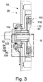
3 : Einen Ausschnitt eines Querschnitts einer Drehmomentübertragungsvorrichtung in einer weiteren speziellen Ausführungsform der Erfindung. -
4 : Den Ausschnitt B aus3 in vergrößerter Ansicht.
-
1 : A cross section of a torque transmission device in a special embodiment of the invention. -
2 : Cut out section A.1 in an enlarged view. -
3 : A section of a cross section of a torque transmission device in a further special embodiment of the invention. -
4th : Cut out section B.3 in an enlarged view.
Der Dämpferausgang
Der Kupplungsausgang
Die Aufnahmehülse
Das um die Drehachse
Das Turbinenrad
Die Trennkupplung
Die erste und zweite Drehmomentübertragungseinheit
An dem Wandlergehäuse
Die axial zwischen der ersten und zweiten Drehmomentübertragungseinheit
In der Aufnahmehülse
In
Der Lagerfluidraum
Dabei wird ein Teil des ersten Fluids durch eine Schmierfluidöffnung
In
BezugszeichenlisteList of reference symbols
- 1010
- DrehmomentübertragungsvorrichtungTorque transfer device
- 1212th
- AntriebselementDrive element
- 1414th
- DämpfereingangDamper input
- 1616
- DrehschwingungsdämpferTorsional vibration damper
- 1818th
- BogenfederBow feather
- 2020th
- DämpferausgangDamper output
- 2222nd
- zweite Drehmomentübertragungseinheitsecond torque transmission unit
- 2424
- KupplungsausgangClutch output
- 2626th
- TrennkupplungDisconnect clutch
- 2828
- erste Drehmomentübertragungseinheitfirst torque transmission unit
- 3030th
- KupplungsbetätigungsvorrichtungClutch actuator
- 3232
- KupplungsausgangClutch output
- 3434
- FliehkraftpendelCentrifugal pendulum
- 3636
- PendelmassenträgerPendulum mass carrier
- 3838
- PendelmassePendulum mass
- 3939
- DruckkolbenPlunger
- 4040
- EingangsnabeInput hub
- 4242
- AufnahmehülseReceiving sleeve
- 4343
- DrehachseAxis of rotation
- 4444
- Gehäusecasing
- 4646
- BetätigungselementActuator
- 4848
- BlattfederLeaf spring
- 5050
- erster Fluidraumfirst fluid space
- 5252
- WandlergehäuseConverter housing
- 5454
- DrehmomentwandlerTorque converter
- 5656
- Eingangentrance
- 5858
- PumpenradImpeller
- 6060
- TurbinenradTurbine wheel
- 6262
- DämpfereingangDamper input
- 6464
- DrehschwingungsdämpferTorsional vibration damper
- 6666
- DruckfederCompression spring
- 6868
- DämpferausgangDamper output
- 7070
- AbtriebsnabeOutput hub
- 7272
- GetriebeeingangswelleTransmission input shaft
- 7474
- KupplungsausgangClutch output
- 7676
- WandlerüberbrückungskupplungTorque converter lockup clutch
- 7878
- KupplungseingangClutch input
- 7979
- DichtelementSealing element
- 8080
- zweiter Fluidraumsecond fluid space
- 8282
- Rotorrotor
- 8484
- ElektromotorElectric motor
- 8686
- AufnahmegehäuseReceiving housing
- 8888
- Statorstator
- 9090
- Trennwandpartition wall
- 9292
- axialer Abschnittaxial section
- 9494
- AbstützlagerSupport bearing
- 9696
- DichtelementSealing element
- 9898
- LagerfluidraumBearing fluid space
- 100100
- DeckblechCover plate
- 102102
- SchmierfluidöffnungLubricating fluid opening
- 104104
- SchmierfluidkreislaufLubricating fluid circuit
- 106106
- SchmierfluidöffnungLubricating fluid opening
- 108108
- SchmierfluidkanalLubricating fluid channel
- 110110
- Kupplungcoupling
- 112112
- KupplungsgehäuseClutch housing
- 114114
- ZentralbohrungCentral bore
ZITATE ENTHALTEN IN DER BESCHREIBUNGQUOTES INCLUDED IN THE DESCRIPTION
Diese Liste der vom Anmelder aufgeführten Dokumente wurde automatisiert erzeugt und ist ausschließlich zur besseren Information des Lesers aufgenommen. Die Liste ist nicht Bestandteil der deutschen Patent- bzw. Gebrauchsmusteranmeldung. Das DPMA übernimmt keinerlei Haftung für etwaige Fehler oder Auslassungen.This list of the documents listed by the applicant was generated automatically and is included solely for the better information of the reader. The list is not part of the German patent or utility model application. The DPMA assumes no liability for any errors or omissions.
Zitierte PatentliteraturPatent literature cited
- DE 102009020672 A1 [0002]DE 102009020672 A1 [0002]
Claims (10)
Priority Applications (2)
| Application Number | Priority Date | Filing Date | Title |
|---|---|---|---|
| DE102019123791.2A DE102019123791A1 (en) | 2019-09-05 | 2019-09-05 | Torque transmission device with a lubricated support bearing |
| PCT/DE2020/100653 WO2021043357A1 (en) | 2019-09-05 | 2020-07-23 | Torque transmitting device with a lubricated support bearing |
Applications Claiming Priority (1)
| Application Number | Priority Date | Filing Date | Title |
|---|---|---|---|
| DE102019123791.2A DE102019123791A1 (en) | 2019-09-05 | 2019-09-05 | Torque transmission device with a lubricated support bearing |
Publications (1)
| Publication Number | Publication Date |
|---|---|
| DE102019123791A1 true DE102019123791A1 (en) | 2021-03-11 |
Family
ID=72046664
Family Applications (1)
| Application Number | Title | Priority Date | Filing Date |
|---|---|---|---|
| DE102019123791.2A Pending DE102019123791A1 (en) | 2019-09-05 | 2019-09-05 | Torque transmission device with a lubricated support bearing |
Country Status (2)
| Country | Link |
|---|---|
| DE (1) | DE102019123791A1 (en) |
| WO (1) | WO2021043357A1 (en) |
Families Citing this family (1)
| Publication number | Priority date | Publication date | Assignee | Title |
|---|---|---|---|---|
| US11364786B2 (en) * | 2020-11-12 | 2022-06-21 | Ford Global Technologies, Llc | Hybrid electric vehicle with a combined torque converter and an electric propulsion motor |
Citations (5)
| Publication number | Priority date | Publication date | Assignee | Title |
|---|---|---|---|---|
| DE102007060165A1 (en) * | 2007-12-13 | 2009-06-18 | Volkswagen Ag | Powertrain module for a motor vehicle |
| DE102009020672A1 (en) * | 2008-06-02 | 2009-12-03 | Luk Lamellen Und Kupplungsbau Beteiligungs Kg | Combined power transmission and drive unit for use in hybrid systems and hybrid systems |
| DE112011100243T5 (en) * | 2010-03-31 | 2012-10-31 | Aisin Aw Co., Ltd. | Hybrid drive device |
| DE102017130271A1 (en) * | 2017-07-17 | 2019-01-17 | Schaeffler Technologies AG & Co. KG | hybrid module |
| DE102017218744A1 (en) * | 2017-10-19 | 2019-04-25 | Zf Friedrichshafen Ag | Hybrid drive module for a motor vehicle |
Family Cites Families (3)
| Publication number | Priority date | Publication date | Assignee | Title |
|---|---|---|---|---|
| CN103158529B (en) * | 2011-12-14 | 2017-09-12 | 福特全球技术公司 | Torsional damper for hybrid electric speed changer |
| DE102017203459A1 (en) * | 2017-03-02 | 2018-09-06 | Zf Friedrichshafen Ag | Gear arrangement for a transmission of a vehicle or the like |
| WO2019070776A1 (en) * | 2017-10-06 | 2019-04-11 | Schaeffler Technologies AG & Co. KG | Motor assembly for hybrid vehicle |
-
2019
- 2019-09-05 DE DE102019123791.2A patent/DE102019123791A1/en active Pending
-
2020
- 2020-07-23 WO PCT/DE2020/100653 patent/WO2021043357A1/en active Application Filing
Patent Citations (5)
| Publication number | Priority date | Publication date | Assignee | Title |
|---|---|---|---|---|
| DE102007060165A1 (en) * | 2007-12-13 | 2009-06-18 | Volkswagen Ag | Powertrain module for a motor vehicle |
| DE102009020672A1 (en) * | 2008-06-02 | 2009-12-03 | Luk Lamellen Und Kupplungsbau Beteiligungs Kg | Combined power transmission and drive unit for use in hybrid systems and hybrid systems |
| DE112011100243T5 (en) * | 2010-03-31 | 2012-10-31 | Aisin Aw Co., Ltd. | Hybrid drive device |
| DE102017130271A1 (en) * | 2017-07-17 | 2019-01-17 | Schaeffler Technologies AG & Co. KG | hybrid module |
| DE102017218744A1 (en) * | 2017-10-19 | 2019-04-25 | Zf Friedrichshafen Ag | Hybrid drive module for a motor vehicle |
Also Published As
| Publication number | Publication date |
|---|---|
| WO2021043357A1 (en) | 2021-03-11 |
Similar Documents
| Publication | Publication Date | Title |
|---|---|---|
| DE102011010342A1 (en) | Torque transfer device | |
| WO2018228634A1 (en) | Torque-transmitting device | |
| WO2012175064A1 (en) | Torque transmission device | |
| DE102019112571B4 (en) | Torque transfer device with dry operated disconnect clutch | |
| EP3172461B1 (en) | Torque-transmitting device and transmission | |
| DE102012206680A1 (en) | Hybrid module for a drive train of a vehicle | |
| DE102019123791A1 (en) | Torque transmission device with a lubricated support bearing | |
| DE102019103771A1 (en) | Transmission unit and hybrid module with a transmission-side partition | |
| DE102019127216B4 (en) | Torque transfer device | |
| DE102019129313A1 (en) | Torque transmission device and hybrid drive device | |
| DE102019116436A1 (en) | Traction device with a separate cone element | |
| DE102019123789B4 (en) | torque transmission device | |
| DE102018122433A1 (en) | Coupling device | |
| DE102021106623B3 (en) | Coupling device with an axial toothing | |
| DE102015205398A1 (en) | Torque transfer device | |
| DE102017210295A1 (en) | Coupling device for transmitting a torque from a flywheel to a drive device and corresponding method | |
| DE102020102361A1 (en) | Coupling device and hybrid module | |
| DE102021100472A1 (en) | Torsional vibration damper and method for removing a torsional vibration damper | |
| DE102018205466A1 (en) | Hybrid drive module for a motor vehicle | |
| DE102017128362A1 (en) | Approach and retarder module | |
| DE102020115291A1 (en) | Torque transfer device | |
| DE102020127711A1 (en) | Torsional vibration damper with a balancing element | |
| WO2021160510A1 (en) | Drive system for a vehicle | |
| DE102018131709A1 (en) | Hybrid module with gearbox-side rotor support | |
| DE102021105885A1 (en) | Hybrid device with a rotor connected to the damper output side |
Legal Events
| Date | Code | Title | Description |
|---|---|---|---|
| R012 | Request for examination validly filed | ||
| R016 | Response to examination communication | ||
| R016 | Response to examination communication |