DE102018009845A1 - Rotor for an electrical machine, in particular a motor vehicle - Google Patents
Rotor for an electrical machine, in particular a motor vehicle Download PDFInfo
- Publication number
- DE102018009845A1 DE102018009845A1 DE102018009845.2A DE102018009845A DE102018009845A1 DE 102018009845 A1 DE102018009845 A1 DE 102018009845A1 DE 102018009845 A DE102018009845 A DE 102018009845A DE 102018009845 A1 DE102018009845 A1 DE 102018009845A1
- Authority
- DE
- Germany
- Prior art keywords
- rotor
- laminated core
- shaft
- rotor shaft
- axial direction
- Prior art date
- Legal status (The legal status is an assumption and is not a legal conclusion. Google has not performed a legal analysis and makes no representation as to the accuracy of the status listed.)
- Withdrawn
Links
- 238000001816 cooling Methods 0.000 claims description 45
- 239000002826 coolant Substances 0.000 claims description 27
- 239000002184 metal Substances 0.000 description 19
- 238000004804 winding Methods 0.000 description 11
- 230000005540 biological transmission Effects 0.000 description 6
- 238000000034 method Methods 0.000 description 4
- 238000011161 development Methods 0.000 description 3
- 230000018109 developmental process Effects 0.000 description 3
- 238000004519 manufacturing process Methods 0.000 description 3
- 229910000976 Electrical steel Inorganic materials 0.000 description 2
- 239000000110 cooling liquid Substances 0.000 description 2
- 239000007788 liquid Substances 0.000 description 2
- 230000001404 mediated effect Effects 0.000 description 2
- 230000002093 peripheral effect Effects 0.000 description 2
- BUHVIAUBTBOHAG-FOYDDCNASA-N (2r,3r,4s,5r)-2-[6-[[2-(3,5-dimethoxyphenyl)-2-(2-methylphenyl)ethyl]amino]purin-9-yl]-5-(hydroxymethyl)oxolane-3,4-diol Chemical compound COC1=CC(OC)=CC(C(CNC=2C=3N=CN(C=3N=CN=2)[C@H]2[C@@H]([C@H](O)[C@@H](CO)O2)O)C=2C(=CC=CC=2)C)=C1 BUHVIAUBTBOHAG-FOYDDCNASA-N 0.000 description 1
- 230000005347 demagnetization Effects 0.000 description 1
- 230000000694 effects Effects 0.000 description 1
- 238000009434 installation Methods 0.000 description 1
- 238000002955 isolation Methods 0.000 description 1
- 239000000463 material Substances 0.000 description 1
- 239000013585 weight reducing agent Substances 0.000 description 1
Images
Classifications
-
- H—ELECTRICITY
- H02—GENERATION; CONVERSION OR DISTRIBUTION OF ELECTRIC POWER
- H02K—DYNAMO-ELECTRIC MACHINES
- H02K1/00—Details of the magnetic circuit
- H02K1/06—Details of the magnetic circuit characterised by the shape, form or construction
- H02K1/22—Rotating parts of the magnetic circuit
- H02K1/32—Rotating parts of the magnetic circuit with channels or ducts for flow of cooling medium
-
- H—ELECTRICITY
- H02—GENERATION; CONVERSION OR DISTRIBUTION OF ELECTRIC POWER
- H02K—DYNAMO-ELECTRIC MACHINES
- H02K1/00—Details of the magnetic circuit
- H02K1/06—Details of the magnetic circuit characterised by the shape, form or construction
- H02K1/22—Rotating parts of the magnetic circuit
- H02K1/28—Means for mounting or fastening rotating magnetic parts on to, or to, the rotor structures
- H02K1/30—Means for mounting or fastening rotating magnetic parts on to, or to, the rotor structures using intermediate parts, e.g. spiders
Landscapes
- Engineering & Computer Science (AREA)
- Power Engineering (AREA)
- Iron Core Of Rotating Electric Machines (AREA)
Abstract
Die Erfindung betrifft einen Rotor (10) für eine elektrische Maschine, mit einer Rotorwelle (12), und mit einem auf der Rotorwelle (12) angeordneten Blechpaket (14), welches in axialer Richtung der Rotorwelle (12) zwischen auf der Rotorwelle (12) angeordneten Endscheiben (18, 20) angeordnet ist, die unter Vermittlung des Blechpakets (14) in axialer Richtung miteinander verspannt sind, wodurch das Blechpaket (14) in axialer Richtung verspannt ist, und mit wenigstens einem innerhalb der Rotorwelle (12) verlaufenden und von einem Kühlmedium zum Kühlen des Rotors (10) durchströmbaren Kühlkanal (22), mittels welchem das Blechpaket (14) mit dem Kühlmedium beaufschlagbar ist, wobei wenigstens eine der Endscheiben (18, 20) mittels einer zentralen, auf die Rotorwelle (12) aufgeschraubten Wellenmutter (24) in axialer Richtung zumindest mittelbar gegen die Rotorwelle (12) gespannt und dadurch an der Rotorwelle (12) gesichert ist.The invention relates to a rotor (10) for an electric machine, comprising a rotor shaft (12), and a laminated core (14) arranged on the rotor shaft (12), which is arranged in the axial direction of the rotor shaft (12) on the rotor shaft (12 arranged end plates (18, 20) is arranged, which are clamped together by means of the laminated core (14) in the axial direction, whereby the laminated core (14) is braced in the axial direction, and with at least one within the rotor shaft (12) extending and by a cooling medium for cooling the rotor (10) can be flowed through the cooling channel (22), by means of which the laminated core (14) is acted upon by the cooling medium, wherein at least one of the end plates (18, 20) by means of a central, on the rotor shaft (12) screwed Shaft nut (24) in the axial direction at least indirectly biased against the rotor shaft (12) and thereby secured to the rotor shaft (12).
Description
Die Erfindung betrifft einen Rotor für eine elektrische Maschine, insbesondere eines Kraftfahrzeugs, gemäß dem Oberbegriff von Patentanspruch 1.The invention relates to a rotor for an electrical machine, in particular a motor vehicle, according to the preamble of claim 1.
Ein solcher Rotor für eine elektrische Maschine ist beispielsweise bereits der
Des Weiteren offenbart die
Aufgabe der vorliegenden Erfindung ist es, einen Rotor der eingangs genannten Art derart weiterzuentwickeln, dass der Rotor auf besonders einfache Weise hergestellt werden kann.Object of the present invention is to develop a rotor of the type mentioned in such a way that the rotor can be produced in a particularly simple manner.
Diese Aufgabe wird durch einen Rotor mit den Merkmalen des Patentanspruchs 1 gelöst. Vorteilhafte Ausgestaltungen mit zweckmäßigen Weiterbildungen der Erfindung sind in den übrigen Ansprüchen angegeben.This object is achieved by a rotor having the features of patent claim 1. Advantageous embodiments with expedient developments of the invention are specified in the remaining claims.
Um einen Rotor der im Oberbegriff des Patentanspruchs 1 angegebenen Art derart weiterzuentwickeln, dass der Rotor besonders einfach und somit zeit- und kostengünstig hergestellt werden kann, ist es erfindungsgemäß vorgesehen, dass der Rotor wenigstens eine zentrale und somit koaxial zu der Rotorwelle angeordnete und auf der Rotorwelle angeordnete sowie auf der Rotorwelle aufgeschraubte Wellenmutter aufweist, mittels welcher wenigstens eine der Endscheiben in axialer Richtung des Rotors zumindest mittelbar, insbesondere direkt, gegen die Rotorwelle gespannt und dadurch an beziehungsweise auf der Rotorwelle, insbesondere in axialer Richtung, gesichert ist. Unter dem Merkmal, dass die wenigstens eine Endscheibe zumindest mittelbar gegen die Rotorwelle gespannt ist, ist zu verstehen, dass die wenigstens eine Endscheibe beispielsweise in axialer Richtung direkt an der Rotorwelle, insbesondere an dem Bund der Rotorwelle, abgestützt und gegen die Rotorwelle, insbesondere gegen den Bund, gespannt ist. Ferner ist es denkbar, dass die wenigstens eine Endscheibe über das Blechpaket sowie gegebenenfalls über die andere Endscheibe in axialer Richtung an der Rotorwelle, insbesondere an einem Bund der Rotorwelle, abgestützt ist und gegen die Rotorwelle, insbesondere gegen den Bund, unter Vermittlung des Blechpakets sowie gegebenenfalls unter Vermittlung der anderen Endscheibe gespannt ist. Der erfindungsgemäße Rotor kann besonders einfach, das heißt im Rahmen eines besonders einfachen Montageprozesses, hergestellt werden, da beispielsweise komplexe Wellen-Naben-Verbindungen zwischen dem Blechpaket und der Rotorwelle und/oder zwischen der jeweiligen Endscheibe und der Rotorwelle entfallen können. Hierzu ist es beispielsweise vorgesehen, dass das Blechpaket nicht direkt an der Rotorwelle gesichert ist, sondern dass das Blechpaket beispielsweise ausschließlich unter Vermittlung der Endscheiben an der Rotorwelle gesichert, das heißt an dieser gehalten ist. Die Endscheiben wirken als Klemm- oder Spannscheiben, mittels welchen das Blechpaket besonders einfach und somit kostengünstig an der Rotorwelle gesichert werden kann. Vorzugsweise ist zumindest eine der Endscheiben als eine Wuchtscheibe ausgebildet, mittels welcher der Rotor zu wuchten oder gewuchtet ist. Beispielsweise sind beide Endscheiben als Wuchtscheiben zum Wuchten des Rotors ausgebildet.In order to develop a rotor specified in the preamble of claim 1 type such that the rotor can be made particularly simple and thus time and cost, it is inventively provided that the rotor at least one central and thus arranged coaxially to the rotor shaft and on the Rotor shaft arranged and screwed onto the rotor shaft shaft nut, by means of which at least one of the end plates in the axial direction of the rotor at least indirectly, in particular directly, clamped against the rotor shaft and thereby secured to or on the rotor shaft, in particular in the axial direction. Under the feature that the at least one end plate is clamped at least indirectly against the rotor shaft, it is to be understood that the at least one end plate, for example in the axial direction directly on the rotor shaft, in particular on the collar of the rotor shaft, supported and against the rotor shaft, in particular against the covenant, is curious. Further, it is conceivable that the at least one end plate on the laminated core and optionally over the other end plate in the axial direction on the rotor shaft, in particular on a collar of the rotor shaft, is supported and against the rotor shaft, in particular against the federal government, mediated by the laminated core and if necessary, under the mediation of the other end plate is stretched. The rotor according to the invention can be produced particularly simply, that is to say in the context of a particularly simple assembly process, since, for example, complex shaft-hub connections between the laminated core and the rotor shaft and / or between the respective end disk and the rotor shaft can be dispensed with. For this purpose, it is for example provided that the laminated core is not secured directly to the rotor shaft, but that the laminated core, for example, exclusively secured by the intermediary of the end plates on the rotor shaft, that is held on this. The end plates act as clamping or clamping disks, by means of which the laminated core can be secured to the rotor shaft in a particularly simple and thus cost-effective manner. Preferably, at least one of the end disks is designed as a balancing disk, by means of which the rotor is to be balanced or balanced. For example, both end plates are designed as balancing disks for balancing the rotor.
Das Blechpaket weist beispielsweise in axialer Richtung des Rotors und somit des Blechpakets aufeinanderfolgende beziehungsweise hintereinander angeordnete Blechlagen auf. Unter dem Merkmal, dass das Blechpaket in axialer Richtung verspannt ist, ist zu verstehen, dass das zwischen den Endscheiben angeordnete Blechpaket in axialer Richtung zwischen den Endscheiben geklemmt beziehungsweise zusammengepresst ist, sodass die Blechlagen mittels der Endscheiben in axialer Richtung zusammengepresst sind. Durch die Sicherung beziehungsweise Halterung oder Befestigung des auch als Rotorkern bezeichneten Blechpakets über die axialen Endscheiben an der Rotorwelle können beispielsweise Innenflächen der Blechlagen, insbesondere in axialer Richtung und/oder in Umfangsrichtung, zumindest im Wesentlichen kräftefrei bleiben und daher unabhängig von der Befestigung gestaltet werden. Außerdem können das Blechpaket und somit die Blechlagen durch eine direkte Kühlung vorteilhaft gekühlt werden. Bei der Kühlung handelt es sich beispielsweise um eine Flüssigkeitskühlung, sodass das Kühlmedium vorzugsweise als eine Kühlflüssigkeit ausgebildet ist. Das Kühlmedium kann beispielsweise aus dem Kühlkanal austreten und in der Folge direkt das Blechpaket, insbesondere zumindest in radialer Richtung von innen nach außen, anströmen und somit direkt berühren, sodass eine besonders vorteilhafte Kühlung darstellbar ist. Damit ist es auch möglich, die radiale Dicke der beispielsweise als Blechschnitte ausgebildeten Blechlagen besonders gering zu halten und hierzu beispielsweise im Vergleich zu herkömmlichen Lösungen auf ein Minimum zu reduzieren, wodurch das Gewicht des Rotors in einem besonders geringen Rahmen gehalten werden kann. Dadurch kann eine besonders vorteilhafte Dynamik realisiert werden.The laminated core has, for example, in the axial direction of the rotor and thus of the laminated core successive or successively arranged sheet metal layers. Under the feature that the laminated core is clamped in the axial direction, it is to be understood that the laminated core arranged between the end plates is clamped or compressed in the axial direction between the end disks, so that the sheet metal layers are pressed together by means of the end disks in the axial direction. By securing or holding or fastening of the laminated core, which is also referred to as a rotor core, over the axial end disks on the rotor shaft, inner surfaces of the sheet metal layers, in particular in the axial direction and / or in the circumferential direction, can remain at least essentially free of force and can therefore be designed independently of the fastening. In addition, the laminated core and thus the sheet metal layers can be advantageously cooled by direct cooling. The cooling is, for example, a liquid cooling, so that the cooling medium is preferably designed as a cooling liquid. The cooling medium can emerge, for example, from the cooling channel and in the sequence directly the laminated core, in particular at least in the radial direction from the inside to the outside, flow and thus touch directly, so that a particularly advantageous cooling can be displayed. Thus, it is also possible, the radial thickness of the sheet metal layers, for example, formed as sheet metal layers To keep particularly low and to reduce this, for example, compared to conventional solutions to a minimum, whereby the weight of the rotor can be kept in a particularly small frame. As a result, a particularly advantageous dynamics can be realized.
In vollständig hergestelltem Zustand des Rotors beziehungsweise der elektrischen Maschine sind beispielsweise an dem Blechpaket Magnete, insbesondere Permanentmagnete, gehalten. Das Kühlmedium kann beispielsweise eine Oberfläche des Blechpakets direkt anströmen und somit direkt berühren. Da die radiale Dicke der Blechlagen gering gehalten werden kann, kann diese innere Oberfläche, welche beispielsweise direkt von dem Kühlmedium angeströmt werden kann, besonders nahe an die Magnete herangebracht werden, wodurch eine besonders vorteilhafte Kühlung realisiert werden kann.In fully manufactured state of the rotor or the electric machine magnets, in particular permanent magnets, for example, held on the laminated core. The cooling medium, for example, directly flow to a surface of the laminated core and thus touch directly. Since the radial thickness of the sheet metal layers can be kept low, this inner surface, which can be flowed directly from the cooling medium, for example, be brought particularly close to the magnets, whereby a particularly advantageous cooling can be realized.
Insgesamt ist erkennbar, dass bei der Erfindung das Blechpaket als verschraubtes Rotorblechpaket ausgebildet ist. Das Blechpaket ist dabei mittels der Wellenmutter und/oder mittels wenigstens einer Schaftschraube verschraubt und somit in axialer Richtung verspannt. In der Folge lässt sich eine besonders magnetnahe Kühlung realisieren. Daran anschließend kann beispielsweise wenigstens ein Wickelkopf einer Wicklung des Rotors mittels des Kühlmediums vorteilhaft gekühlt werden. Der Erfindung liegen insbesondere die folgenden Erkenntnisse zugrunde: Bei der Entwicklung einer elektrischen Maschine, insbesondere eines Elektromotors, ist eines der Hauptziele eine hohe Leistungs- und Drehmomentdichte bei gleichzeitig gutem Wirkungsgrad und geringem Ressourcenverbrauch. Dabei werden sowohl die mechanischen als auch die thermischen Grenzen so weit wie möglich ausgenutzt. Die Erfindung ermöglicht nun ein Wegfallen komplexer Wellen-Naben-Verbindungen im Vergleich zu herkömmlichen Lösungen, wobei das Blechpaket mittels der wenigstens einen Wellenmutter und/oder mittels wenigstens einer Schaftschraube beziehungsweise mittels mehrerer Schaftschrauben verschraubt und dadurch axial verspannt wird. Hierdurch kann eine besonders vorteilhafte Anbindung des Blechpakets über die Endscheiben an die Rotorwelle realisiert werden, sodass eine besonders vorteilhafte Drehmomentübertragung darstellbar ist. Hierunter ist insbesondere zu verstehen, dass besonders hohe Drehmomente zwischen dem Blechpaket und der Rotorwelle, insbesondere über die Endscheiben, übertragen werden kann. Dies ermöglicht eine radiale Einsparung des einfach auch als Blech bezeichneten Blechpakets beziehungsweise dessen in radialer Richtung verlaufender Dicke, wodurch Freiraum für eine effiziente Rotor- und Wickelkopfkühlung geschaffen wird.Overall, it can be seen that in the invention, the laminated core is designed as a bolted rotor laminated core. The laminated core is screwed by means of the shaft nut and / or by means of at least one shaft screw and thus clamped in the axial direction. As a result, a particularly magnetic cooling can be realized. Subsequently, for example, at least one end winding of a winding of the rotor can be advantageously cooled by means of the cooling medium. The invention is based, in particular, on the following findings: In the development of an electrical machine, in particular an electric motor, one of the main goals is a high power and torque density with simultaneously good efficiency and low resource consumption. Both mechanical and thermal limits are exploited as much as possible. The invention now makes it possible to omit complex shaft-hub connections in comparison to conventional solutions, wherein the laminated core is screwed by means of the at least one shaft nut and / or by means of at least one shaft screw or by means of several shaft screws and thereby axially braced. In this way, a particularly advantageous connection of the laminated core can be realized via the end plates to the rotor shaft, so that a particularly advantageous torque transmission can be displayed. This is to be understood in particular that particularly high torques between the laminated core and the rotor shaft, in particular via the end plates, can be transmitted. This allows a radial saving of the sheet metal stack, which is also referred to simply as a metal sheet, or its thickness extending in the radial direction, thereby creating free space for efficient rotor and winding head cooling.
Mit anderen Worten ist bei der Erfindung ein axiales Verspannen des auch als Elektroband bezeichneten Blechpakets mittels der Wellenmutter und/oder mittels der Schaftschrauben vorgesehen. In der Folge kann ein besonders großer Innendurchmesser des Blechpakets geschaffen werden, wodurch im Vergleich zu herkömmlichen Lösungen eine Material- und Gewichtsersparnis realisiert werden kann. Der Innendurchmesser begrenzt beispielsweise eine Öffnung, insbesondere eine Durchgangsöffnung, des Blechpakets, wobei beispielsweise die Rotorwelle in der Durchgangsöffnung aufgenommen ist und beispielsweise die Durchgangsöffnung durchdringt.In other words, in the invention, an axial bracing of the laminated core, also referred to as electrical steel, is provided by means of the shaft nut and / or by means of the shaft screws. As a result, a particularly large inner diameter of the laminated core can be created, which in comparison to conventional solutions, a material and weight savings can be realized. The inner diameter limits, for example, an opening, in particular a passage opening, of the laminated core, wherein, for example, the rotor shaft is received in the passage opening and, for example, penetrates the passage opening.
Als das Kühlmedium wird beispielsweise ein Öl, insbesondere ein Getriebeöl, verwendet. Da der Kühlkanal innerhalb der einfach auch als Welle bezeichneten Rotorwelle verläuft, kann das Kühlmedium in der Welle, insbesondere dem Blechpaket, zugeführt werden.As the cooling medium, for example, an oil, in particular a transmission oil used. Since the cooling channel extends within the rotor shaft, which is simply referred to as a shaft, the cooling medium in the shaft, in particular the laminated core, can be supplied.
Das Blechpaket ist beispielsweise zumindest in einem in axialer Richtung zwischen den Endscheiben verlaufenden Längenbereich in radialer Richtung nach außen hin von der Rotorwelle beabstandet, wodurch ein in radialer Richtung zwischen dem Längenbereich und der Rotorwelle angeordneter und beispielsweise in radialer Richtung nach außen hin durch das Blechpaket und in radialer Richtung nach innen hin durch den Längenbereich begrenzter Zwischenraum gebildet ist. Dabei mündet beispielsweise der Kühlkanal, insbesondere über wenigstens eine Austrittsöffnung, in den Zwischenraum, sodass das den Kühlkanal durchströmende Kühlmedium über die Austrittsöffnung in den Zwischenraum strömen kann. In der Folge kann beispielsweise das auch als Rotorblech bezeichnete Blechpaket in radialer Richtung von innen nach außen mit dem über die Austrittsöffnung aus dem Kühlkanal austretenden Kühlmedium bedüst und somit beaufschlagt beziehungsweise versorgt werden. In der Folge kann eine Filmkühlung an dem Rotorblech gebildet werden. Danach strömt das Kühlmedium beispielsweise über die Wickelköpfe der Wicklung ab, sodass nach der Filmkühlung des Rotorbleches eine vorteilhafte Wickelkopfkühlung dargestellt werden kann. Insbesondere ermöglicht die Erfindung die Realisierung der folgenden Vorteile:
- - Gewichtsreduktion aufgrund des Einsparens von Elektroband
- - Kostenreduktion aufgrund einer Vereinfachung der Ausgestaltung der Welle
- - Erhöhung der Kühlleistung aufgrund geringem thermischen Durchgangswiderstand und großer nutzbarer Oberfläche
- - integrierte Wickelkopfkühlung im Anschluss an die Rotorkühlung möglich, wobei in einem Kühlkreis ein Volumenstrom des Kühlmediums vorteilhaft gering gehalten werden kann.
- - Weight reduction due to the saving of electrical steel
- - Cost reduction due to a simplification of the design of the shaft
- - Increasing the cooling capacity due to low thermal resistance and large usable surface
- - integrated winding winding cooling following the rotor cooling possible, wherein in a cooling circuit, a volume flow of the cooling medium can be advantageously kept low.
Weitere Vorteile, Merkmale und Einzelheiten der Erfindung ergeben sich aus der nachfolgenden Beschreibung bevorzugter Ausführungsbeispiele sowie anhand der Zeichnung. Die vorstehend in der Beschreibung genannten Merkmale und Merkmalskombinationen sowie die nachfolgend in der Figurenbeschreibung genannten und/oder in den Figuren alleine gezeigten Merkmale und Merkmalskombinationen sind nicht nur in der jeweils angegebenen Kombination, sondern auch in anderen Kombinationen oder in Alleinstellung verwendbar, ohne den Rahmen der Erfindung zu verlassen.Further advantages, features and details of the invention will become apparent from the following description of preferred embodiments and from the drawing. The features and feature combinations mentioned above in the description as well as the features and feature combinations mentioned below in the description of the figures and / or in the figures alone can be used not only in the respectively specified combination but also in other combinations or in isolation, without the scope of To leave invention.
Die Zeichnung zeigt in:
-
1 eine schematische und geschnittene Seitenansicht eines erfindungsgemäßen Rotors gemäß einer ersten Ausführungsform für eine elektrische Maschine; -
2 ausschnittsweise eine schematische und geschnittene Seitenansicht des Rotors gemäß1 ; -
3 eine schematische und geschnittene Seitenansicht des Rotors gemäß einer zweiten Ausführungsform; -
4 ausschnittsweise eine schematische und geschnittene Seitenansicht des Rotors gemäß3 ; -
5 eine schematische und geschnittene Seitenansicht des Rotors gemäß einer dritten Ausführungsform; -
6 ausschnittsweise eine schematische und geschnittene Seitenansicht des Rotors gemäß5 ; -
7 eine schematische und geschnittene Seitenansicht des Rotors gemäß einer vierten Ausführungsform; -
8 ausschnittsweise eine schematische und geschnittene Seitenansicht des Rotors gemäß7 ; -
9 eine schematische und geschnittene Seitenansicht des Rotors gemäß einer fünften Ausführungsform; -
10 ausschnittsweise eine schematische und geschnittene Seitenansicht des Rotors gemäß9 ; -
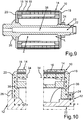
11 eine schematische und geschnittene Seitenansicht des Rotors gemäß einer sechsten Ausführungsform; -
12 ausschnittsweise eine schematische und geschnittene Seitenansicht des Rotors gemäß11 ; -
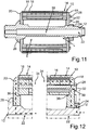
13 eine schematische und geschnittene Seitenansicht des Rotors gemäß einer siebten Ausführungsform; -
14 ausschnittsweise eine schematische und geschnittene Seitenansicht des Rotors gemäß13 ; -
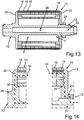
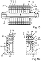
15 eine schematische und geschnittene Seitenansicht des Rotors gemäß einer achten Ausführungsform; -
16 ausschnittsweise eine schematische und geschnittene Seitenansicht des Rotors gemäß15 ; -
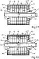
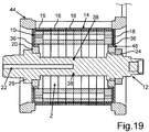
17 eine schematische und geschnittene Seitenansicht des Rotors gemäß einer neunten Ausführungsform; -
18 eine weitere schematische und geschnittene Seitenansicht des Rotors gemäß17 ; und -
19 eine weitere schematische und geschnittene Seitenansicht des Rotors gemäß17 .
-
1 a schematic and sectional side view of a rotor according to the invention according to a first embodiment of an electric machine; -
2 partially a schematic and sectional side view of the rotor according to1 ; -
3 a schematic and sectional side view of the rotor according to a second embodiment; -
4 partially a schematic and sectional side view of the rotor according to3 ; -
5 a schematic and sectional side view of the rotor according to a third embodiment; -
6 partially a schematic and sectional side view of the rotor according to5 ; -
7 a schematic and sectional side view of the rotor according to a fourth embodiment; -
8th partially a schematic and sectional side view of the rotor according to7 ; -
9 a schematic and sectional side view of the rotor according to a fifth embodiment; -
10 partially a schematic and sectional side view of the rotor according to9 ; -
11 a schematic and sectional side view of the rotor according to a sixth embodiment; -
12 partially a schematic and sectional side view of the rotor according to11 ; -
13 a schematic and sectional side view of the rotor according to a seventh embodiment; -
14 partially a schematic and sectional side view of the rotor according to13 ; -
15 a schematic and sectional side view of the rotor according to an eighth embodiment; -
16 partially a schematic and sectional side view of the rotor according to15 ; -
17 a schematic and sectional side view of the rotor according to a ninth embodiment; -
18 a further schematic and sectional side view of the rotor according to17 ; and -
19 a further schematic and sectional side view of the rotor according to17 ,
In den Fig. sind gleiche oder funktionsgleiche Elemente mit gleichen Bezugszeichen versehen.In the figures, the same or functionally identical elements are provided with the same reference numerals.
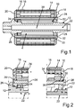
Der Rotor
In axialer Richtung des Rotors
Der Rotor
Um nun den Rotor
Darüber hinaus sind Schraubelemente in Form von Schaftschrauben
In
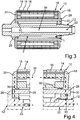
Besonders gut aus
Das Blechpaket
Da die Schaftschrauben
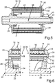
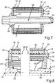
Schließlich veranschaulichen
Bei der Entwicklung einer beispielsweise als Elektromotor ausgebildeten oder als Elektromotor betreibbaren elektrischen Maschine ist eines der Hauptziele eine hohe Leistungs- und Drehmomentdichte bei gleichzeitig sehr gutem Wirkungsgrad und geringem Ressourcenverbrauch. Dabei werden sowohl die mechanischen als auch die thermischen Grenzen soweit möglich ausgenutzt. Zudem ist ein möglichst einfacher Montageprozess mit geringer Bauteilvielfalt vorteilhaft. Um die mechanischen und thermischen Grenzen so weit wie möglich ausnutzen zu können, darf eine maximale Betriebstemperatur entsprechend der Temperaturklasse nicht überschritten werden. Insbesondere droht bei zu hoher thermischer Belastung eine Entmagnetisierung, insbesondere von Magneten, die beispielsweise als Permanentmagnete ausgebildet und/oder an dem Blechpaket
Im Folgenden wird anhand von
Im Weiteren wird ein Kühlkonzept beschrieben. Eine Zuführung des Kühlmediums erfolgt über den beispielsweise als Axialbohrung ausgebildeten Kühlkanal
BezugszeichenlisteLIST OF REFERENCE NUMBERS
- 1010
- Rotorrotor
- 1212
- Rotorwellerotor shaft
- 1414
- Blechpaketlaminated core
- 1616
- Blechlagesheet metal layer
- 1818
- Endscheibeend disk
- 2020
- Endscheibeend disk
- 2222
- Kühlkanalcooling channel
- 2424
- Wellenmuttershaft nut
- 2626
- BundFederation
- 2828
- Schaftschraubeset screw
- 3030
- DurchgangsöffnungThrough opening
- 3232
- Schraubenkopfscrew head
- 3434
- gestrichelte Liniedashed line
- 3636
- Anschlagattack
- 3838
- Austrittsöffnungoutlet opening
- 4040
- Sicherungsringcirclip
- 4242
- Hülseshell
- 4444
- Gehäusecasing
- 4646
- Öffnungopening
- LL
- Längenbereichlength range
- ZZ
- Zwischenraumgap
ZITATE ENTHALTEN IN DER BESCHREIBUNG QUOTES INCLUDE IN THE DESCRIPTION
Diese Liste der vom Anmelder aufgeführten Dokumente wurde automatisiert erzeugt und ist ausschließlich zur besseren Information des Lesers aufgenommen. Die Liste ist nicht Bestandteil der deutschen Patent- bzw. Gebrauchsmusteranmeldung. Das DPMA übernimmt keinerlei Haftung für etwaige Fehler oder Auslassungen.This list of the documents listed by the applicant has been generated automatically and is included solely for the better information of the reader. The list is not part of the German patent or utility model application. The DPMA assumes no liability for any errors or omissions.
Zitierte PatentliteraturCited patent literature
- EP 0215129 A1 [0002]EP 0215129 A1 [0002]
- EP 1385253 A1 [0003]EP 1385253 A1 [0003]
Claims (6)
Priority Applications (1)
| Application Number | Priority Date | Filing Date | Title |
|---|---|---|---|
| DE102018009845.2A DE102018009845A1 (en) | 2018-12-14 | 2018-12-14 | Rotor for an electrical machine, in particular a motor vehicle |
Applications Claiming Priority (1)
| Application Number | Priority Date | Filing Date | Title |
|---|---|---|---|
| DE102018009845.2A DE102018009845A1 (en) | 2018-12-14 | 2018-12-14 | Rotor for an electrical machine, in particular a motor vehicle |
Publications (1)
| Publication Number | Publication Date |
|---|---|
| DE102018009845A1 true DE102018009845A1 (en) | 2019-06-27 |
Family
ID=66767885
Family Applications (1)
| Application Number | Title | Priority Date | Filing Date |
|---|---|---|---|
| DE102018009845.2A Withdrawn DE102018009845A1 (en) | 2018-12-14 | 2018-12-14 | Rotor for an electrical machine, in particular a motor vehicle |
Country Status (1)
| Country | Link |
|---|---|
| DE (1) | DE102018009845A1 (en) |
Cited By (7)
| Publication number | Priority date | Publication date | Assignee | Title |
|---|---|---|---|---|
| WO2021099045A1 (en) | 2019-11-22 | 2021-05-27 | Zf Friedrichshafen Ag | Rotor for an electrical machine |
| WO2021185490A1 (en) * | 2020-03-18 | 2021-09-23 | Mahle International Gmbh | Rotor of an electric motor |
| DE102021202703A1 (en) | 2021-03-19 | 2022-09-22 | Volkswagen Aktiengesellschaft | Rotor of an electrical machine |
| EP4395134A1 (en) * | 2022-12-28 | 2024-07-03 | Toyota Jidosha Kabushiki Kaisha | Rotor |
| DE102023102138A1 (en) | 2023-01-30 | 2024-08-01 | Bayerische Motoren Werke Aktiengesellschaft | Rotor for an electric machine and motor vehicle with at least one electric machine |
| DE102023105236A1 (en) | 2023-03-03 | 2024-09-05 | Bayerische Motoren Werke Aktiengesellschaft | Rotor for an electrical machine, in particular of a motor vehicle, and electrical machine, in particular for a motor vehicle |
| DE102023107821A1 (en) * | 2023-03-28 | 2024-10-02 | Valeo Eautomotive Germany Gmbh | Rotor for an electrical machine with improved fixation of a shaft nut for axial securing of a rotor laminated core |
Citations (2)
| Publication number | Priority date | Publication date | Assignee | Title |
|---|---|---|---|---|
| EP0215129A1 (en) | 1985-02-28 | 1987-03-25 | Fanuc Ltd. | Permanent magnet field rotor assembly |
| EP1385253A1 (en) | 2002-07-26 | 2004-01-28 | MS-Technologie GmbH | High speed rotor |
-
2018
- 2018-12-14 DE DE102018009845.2A patent/DE102018009845A1/en not_active Withdrawn
Patent Citations (2)
| Publication number | Priority date | Publication date | Assignee | Title |
|---|---|---|---|---|
| EP0215129A1 (en) | 1985-02-28 | 1987-03-25 | Fanuc Ltd. | Permanent magnet field rotor assembly |
| EP1385253A1 (en) | 2002-07-26 | 2004-01-28 | MS-Technologie GmbH | High speed rotor |
Cited By (8)
| Publication number | Priority date | Publication date | Assignee | Title |
|---|---|---|---|---|
| WO2021099045A1 (en) | 2019-11-22 | 2021-05-27 | Zf Friedrichshafen Ag | Rotor for an electrical machine |
| WO2021185490A1 (en) * | 2020-03-18 | 2021-09-23 | Mahle International Gmbh | Rotor of an electric motor |
| DE102021202703A1 (en) | 2021-03-19 | 2022-09-22 | Volkswagen Aktiengesellschaft | Rotor of an electrical machine |
| EP4395134A1 (en) * | 2022-12-28 | 2024-07-03 | Toyota Jidosha Kabushiki Kaisha | Rotor |
| DE102023102138A1 (en) | 2023-01-30 | 2024-08-01 | Bayerische Motoren Werke Aktiengesellschaft | Rotor for an electric machine and motor vehicle with at least one electric machine |
| DE102023105236A1 (en) | 2023-03-03 | 2024-09-05 | Bayerische Motoren Werke Aktiengesellschaft | Rotor for an electrical machine, in particular of a motor vehicle, and electrical machine, in particular for a motor vehicle |
| WO2024183997A1 (en) | 2023-03-03 | 2024-09-12 | Bayerische Motoren Werke Aktiengesellschaft | Rotor for an electrical machine, in particular belonging to a motor vehicle, and electrical machine, in particular for a motor vehicle |
| DE102023107821A1 (en) * | 2023-03-28 | 2024-10-02 | Valeo Eautomotive Germany Gmbh | Rotor for an electrical machine with improved fixation of a shaft nut for axial securing of a rotor laminated core |
Similar Documents
| Publication | Publication Date | Title |
|---|---|---|
| DE102018009845A1 (en) | Rotor for an electrical machine, in particular a motor vehicle | |
| EP3673568B1 (en) | Multipart rotor shaft for an electric machine | |
| EP3480929B1 (en) | Cooled housing for the stator of a direct drive | |
| DE102013208980A1 (en) | retarder | |
| DE102012106740A1 (en) | Electric machine for a hybrid or electric vehicle | |
| WO2015018575A1 (en) | Cooling system for a hybrid drive arrangement | |
| DE102015014535A1 (en) | Electric machine, in particular for a motor vehicle | |
| DE102019120787A1 (en) | Electric drive unit, hybrid module and drive arrangement for a motor vehicle | |
| WO2024120778A1 (en) | Electric wheel hub drive for a motor vehicle | |
| DE102014202912A1 (en) | Electric machine with a fluid channel | |
| DE102015007138A1 (en) | Rotor for an electric machine of a drive train of a motor vehicle, drive train for a motor vehicle with such a rotor and method for mounting a rotor | |
| DE102022213027A1 (en) | Rotor and electric machine | |
| WO2017186755A1 (en) | Drive system for individually driving two individual propellers of a double propeller | |
| DE102021213255A1 (en) | Rotor arrangement for an electric machine, electric machine with the rotor arrangement and vehicle with the electric machine | |
| EP3807112A1 (en) | Drive unit for a powertrain of an electrically driveable motor vehicle, and drive assembly | |
| DE102017122908A1 (en) | Segmented switched reluctance motor for force-current electrification | |
| WO2023217503A1 (en) | Axial flow machine for a motor vehicle, in particular for a car | |
| DE102012204774A1 (en) | Electric machine assembly of motor vehicle, has stator which is supported on housing via annular stator carrier that is inserted into receiving opening of hybrid housing | |
| WO2019206358A1 (en) | Clutch arrangement with support component formed as a sheet-metal part and connected to a rotor carrier; and drivetrain | |
| EP3668808A1 (en) | Direct drive for border winder in metalworking | |
| DE102012223372A1 (en) | Electric machine i.e. inner rotor-motor, for hybrid drive arrangement for vehicle, has stator with stator carrier, and coolant supply element discharging coolant from coolant channel and arranged axially at radial outer edge of carrier | |
| DE102020210497A1 (en) | Rotor of a permanently excited electrical machine | |
| DE102020209709A1 (en) | electrical machine | |
| DE102012003101A1 (en) | Stator carrier for an electric machine | |
| WO2025040415A1 (en) | Stator arrangement for an electric machine with simplified assembly of the stator laminated core in the stator housing |
Legal Events
| Date | Code | Title | Description |
|---|---|---|---|
| R230 | Request for early publication | ||
| R081 | Change of applicant/patentee |
Owner name: DAIMLER AG, DE Free format text: FORMER OWNER: DAIMLER AG, 70327 STUTTGART, DE |
|
| R119 | Application deemed withdrawn, or ip right lapsed, due to non-payment of renewal fee |