EP0215129A1 - Permanent magnet field rotor assembly - Google Patents
Permanent magnet field rotor assembly Download PDFInfo
- Publication number
- EP0215129A1 EP0215129A1 EP86901515A EP86901515A EP0215129A1 EP 0215129 A1 EP0215129 A1 EP 0215129A1 EP 86901515 A EP86901515 A EP 86901515A EP 86901515 A EP86901515 A EP 86901515A EP 0215129 A1 EP0215129 A1 EP 0215129A1
- Authority
- EP
- European Patent Office
- Prior art keywords
- rotor shaft
- yokes
- end plates
- permanent magnet
- rotor assembly
- Prior art date
- Legal status (The legal status is an assumption and is not a legal conclusion. Google has not performed a legal analysis and makes no representation as to the accuracy of the status listed.)
- Granted
Links
Images
Classifications
-
- H—ELECTRICITY
- H02—GENERATION; CONVERSION OR DISTRIBUTION OF ELECTRIC POWER
- H02K—DYNAMO-ELECTRIC MACHINES
- H02K1/00—Details of the magnetic circuit
- H02K1/06—Details of the magnetic circuit characterised by the shape, form or construction
- H02K1/22—Rotating parts of the magnetic circuit
- H02K1/27—Rotor cores with permanent magnets
- H02K1/2706—Inner rotors
- H02K1/272—Inner rotors the magnetisation axis of the magnets being perpendicular to the rotor axis
- H02K1/274—Inner rotors the magnetisation axis of the magnets being perpendicular to the rotor axis the rotor consisting of two or more circumferentially positioned magnets
- H02K1/2753—Inner rotors the magnetisation axis of the magnets being perpendicular to the rotor axis the rotor consisting of two or more circumferentially positioned magnets the rotor consisting of magnets or groups of magnets arranged with alternating polarity
- H02K1/276—Magnets embedded in the magnetic core, e.g. interior permanent magnets [IPM]
- H02K1/2766—Magnets embedded in the magnetic core, e.g. interior permanent magnets [IPM] having a flux concentration effect
- H02K1/2773—Magnets embedded in the magnetic core, e.g. interior permanent magnets [IPM] having a flux concentration effect consisting of tangentially magnetized radial magnets
-
- Y—GENERAL TAGGING OF NEW TECHNOLOGICAL DEVELOPMENTS; GENERAL TAGGING OF CROSS-SECTIONAL TECHNOLOGIES SPANNING OVER SEVERAL SECTIONS OF THE IPC; TECHNICAL SUBJECTS COVERED BY FORMER USPC CROSS-REFERENCE ART COLLECTIONS [XRACs] AND DIGESTS
- Y10—TECHNICAL SUBJECTS COVERED BY FORMER USPC
- Y10T—TECHNICAL SUBJECTS COVERED BY FORMER US CLASSIFICATION
- Y10T29/00—Metal working
- Y10T29/49—Method of mechanical manufacture
- Y10T29/49002—Electrical device making
- Y10T29/49009—Dynamoelectric machine
- Y10T29/49012—Rotor
Definitions
- the present invention relates to a permanent-magnet rotor assembly and, more specifically, to improvements in a fastening structure for fastening end plates to the rotor shaft of a permanent-magnet rotor assembly.
- a permanent-magnet rotor assembly comprises a rotor shaft, a plurality of yokes extending along the axis of the rotor shaft and arranged around the rotor shaft at circumferential intervals, permanent magnets each being held between the two adjacent yokes, and a pair of end plates attached to the opposite ends of the yokes and fastened to the rotor shaft, respectively.
- the end plates are placed in contact with the yokes and the permanent magnets, and are fastened to the opposite ends of the yokes, respectively, with stud bolts or fastening bolts penetrating the yokes. Therefore, the end plates must be formed of a nonmagnetic material, such as a stainless steel, to prevent a short-circuiting of the magnetic paths through the end plates.
- the end plates must be firmly secured to the rotor shaft. Accordingly, it has been a conventional practice to form an end plate integrally with a boss having a large wall thickness, by casting and/or machining and to secure the end plate to a rotor shaft by fitting the rotor shaft in the boss by a shrinkage fit.
- nonmagnetic materials in general, are expensive, forming an end plate integrally with a boss having a large wall thickness of a non- magnetic material is very costly.
- the present invention provides a permanent magnet rotor assembly comprising a rotor shaft, a plurality of yokes arranged around the rotor shaft at circumferential intervals and extending along the axis of the rotor shaft, permanent magnets each being held between the two adjacent yokes, a pair of end plates attached to the opposite ends of the yokes, respectively, each end plate being formed of a nonmagnetic material and having in the central portion thereof a boss capable of fitting on the rotor shaft, the boss being secured to the rotor shaft by the compressive force of a fastening ring fitted on the boss by a shrinkage fit.
- the boss of the end plate is secured firmly to the rotor shaft by the compressive force of the fastening ring.
- the fastening ring need not be formed of a nonmagnetic material, and hence the fastening ring is inexpensive.
- the end plate formed of a nonmagnetic material may have a small thickness, the end plate also is inexpensive.
- the end plate can be secured to the rotor shaft without requiring a welding process, thermal deformation of the rotor shaft and deterioration of the rotational accuracy of the rotor assembly can be prevented.
- the boss of the end plate is formed by drawing. Therefore, the end plate can be easily manufactured at a low cost by using the least necessary amount of a nonmagnetic material.
- a permanent magnet rotor assembly has a rotor shaft 11.
- Four yokes 12 extending axially of the rotor shaft are arranged around the rotor shaft at circumferential intervals.
- Each yoke 12 consists of a plurality of thin electromagnetic steel plates laminated along the axial direction.
- Permanent magnets 13 each having a rectangular cross section are extended in the axial direction and are held between the two adjacent yokes 12, respectively, with the longer sides thereof extended radially.
- the electromagnetic steel plates forming the yokes 12 each have a substantially sectorial shape and are provided at the opposite ends of the outer edges thereof with projections 12a and 12b which engage the outer corners of the permanent magnet 13 to restrain the same from radially slipping out of position.
- the permanent magnets 13 each have magnetic poles of opposite nature, namely, an N-pole and an S-pole, in the circumferentially opposite sides thereof.
- the permanent magnets 13 are arranged so that the same magnetic poles of the two adjacent permanent magnets 13 are disposed on the opposite sides of each yoke 12. Accordingly, the alternate yokes 12 form field poles of opposite nature.
- a pair of end plates 14 and 15 are provided on the axially opposite ends of the yokes 12, respectively.
- the end plates 14 and 15 are joined to the axially opposite ends of the yokes 12 by means of fastening bolts 16 inserted axially through the yokes 12, and nuts 17, respectively.
- the end plates 14 and 15 restrict the axial movement of the permanent magnets 13.
- the end plates 14 and 15 are each formed of a thin nonmagnetic plate, namely, a thin stainless steel plate.
- the end plates 14 and 15 have, in the respective central portions thereof, bosses 14a and 15a fitting the outer circumference of the rotor shaft 11, respectively.
- the permanent magnet rotor assembly is provided with fastening rings 18 and 19 fitted on the bosses 14a and 15a of the end plates 14 and 15, respectively, by thermal insertion.
- the fastening rings 18 and 19 are fitted on the bosses 14a and 15a of the end plates 14 and 15, respectively, by thermal insertion, the bosses 14a and 15a are secured firmly to the rotor shaft 11 by radial compressive pressure produced by the thermal shrinkage of the fastening rings 18 and 19.
- the fastening rings 18 and 19 need not be formed of a nonmagnetic material, but may be formed of an inexpensive ferrous metal. Therefore, the fastening rings are manufactured at a low cost.
- the end plates 14 and 15 are placed contiguously to the yokes 12, they must be formed of a nonmagnetic material.
- the respective entire portions of the end plates 14 and 15 including the bosses 14a and 15a each can be formed of thin plates of a nonmagnetic material, the end plates 14 and 15 can be manufactured at a low cost.
- the bosses 14a and 15a of the end plates 14 and 15, in particular, can be easily formed at a low cost using the least necessary amount of material by drawing a work formed by punching a thin plate.
- each yoke may be a single metallic body.
- the permanent magnet rotor assembly according to the present invention is applicable to motors and generators of the permanent magnet type for various purposes.
Abstract
Description
- The present invention relates to a permanent-magnet rotor assembly and, more specifically, to improvements in a fastening structure for fastening end plates to the rotor shaft of a permanent-magnet rotor assembly.
- Generally, a permanent-magnet rotor assembly comprises a rotor shaft, a plurality of yokes extending along the axis of the rotor shaft and arranged around the rotor shaft at circumferential intervals, permanent magnets each being held between the two adjacent yokes, and a pair of end plates attached to the opposite ends of the yokes and fastened to the rotor shaft, respectively.
- In such a permanent magnet rotor assembly, the end plates are placed in contact with the yokes and the permanent magnets, and are fastened to the opposite ends of the yokes, respectively, with stud bolts or fastening bolts penetrating the yokes. Therefore, the end plates must be formed of a nonmagnetic material, such as a stainless steel, to prevent a short-circuiting of the magnetic paths through the end plates.
- On the other hand, the end plates must be firmly secured to the rotor shaft. Accordingly, it has been a conventional practice to form an end plate integrally with a boss having a large wall thickness, by casting and/or machining and to secure the end plate to a rotor shaft by fitting the rotor shaft in the boss by a shrinkage fit. However, since nonmagnetic materials, in general, are expensive, forming an end plate integrally with a boss having a large wall thickness of a non- magnetic material is very costly.
- It is possible to secure an end plate having a boss having a small wall thickness and formed of a nonmagnetic material to a rotor shaft by welding the boss to the rotor shaft. This method reduces the cost of the end plate and can secure the end plate firmly to the rotor shaft, but this method will possibly cause thermal deformation of the rotor shaft, which deteriorates the rotational accuracy of the rotor assembly.
- Accordingly, it has been desired by the industry to develop a permanent magnet rotor having inexpensive end plates which can secured firmly to the rotor shaft without deteriorating the rotational accuracy of the rotor assembly.
- The present invention provides a permanent magnet rotor assembly comprising a rotor shaft, a plurality of yokes arranged around the rotor shaft at circumferential intervals and extending along the axis of the rotor shaft, permanent magnets each being held between the two adjacent yokes, a pair of end plates attached to the opposite ends of the yokes, respectively, each end plate being formed of a nonmagnetic material and having in the central portion thereof a boss capable of fitting on the rotor shaft, the boss being secured to the rotor shaft by the compressive force of a fastening ring fitted on the boss by a shrinkage fit.
- In the permanent magnet rotor assembly according to the present invention, the boss of the end plate is secured firmly to the rotor shaft by the compressive force of the fastening ring. The fastening ring need not be formed of a nonmagnetic material, and hence the fastening ring is inexpensive. On the other hand, since the end plate formed of a nonmagnetic material may have a small thickness, the end plate also is inexpensive. Furthermore, since the end plate can be secured to the rotor shaft without requiring a welding process, thermal deformation of the rotor shaft and deterioration of the rotational accuracy of the rotor assembly can be prevented.
- Preferably, the boss of the end plate is formed by drawing. Therefore, the end plate can be easily manufactured at a low cost by using the least necessary amount of a nonmagnetic material.
- The above and other features and advantages of the present invention will become more apparent from the following description taken in conjunction with the accompanying drawings.
-
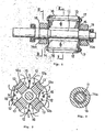
- Figure 1 is a longitudinal sectional view of a permanent magnet rotor assembly, in a preferred embodiment, according to the present invention;
- Figure 2 is a sectional view taken on line II-II in Fig. 1; and
- Figure 3 is a sectional view taken on line III-III in Fig. 1.
- Referring to Figs. 1 to 3 showing a preferred embodiment of the present invention, a permanent magnet rotor assembly has a
rotor shaft 11. Fouryokes 12 extending axially of the rotor shaft are arranged around the rotor shaft at circumferential intervals. Eachyoke 12 consists of a plurality of thin electromagnetic steel plates laminated along the axial direction. -
Permanent magnets 13 each having a rectangular cross section are extended in the axial direction and are held between the twoadjacent yokes 12, respectively, with the longer sides thereof extended radially. The electromagnetic steel plates forming theyokes 12 each have a substantially sectorial shape and are provided at the opposite ends of the outer edges thereof withprojections permanent magnet 13 to restrain the same from radially slipping out of position. - The
permanent magnets 13 each have magnetic poles of opposite nature, namely, an N-pole and an S-pole, in the circumferentially opposite sides thereof. Thepermanent magnets 13 are arranged so that the same magnetic poles of the two adjacentpermanent magnets 13 are disposed on the opposite sides of eachyoke 12. Accordingly, thealternate yokes 12 form field poles of opposite nature. - A pair of
end plates yokes 12, respectively. Theend plates yokes 12 by means of fasteningbolts 16 inserted axially through theyokes 12, andnuts 17, respectively. Thus, theend plates permanent magnets 13. - The
end plates end plates bosses rotor shaft 11, respectively. - The permanent magnet rotor assembly is provided with
fastening rings 18 and 19 fitted on thebosses end plates fastening rings 18 and 19 are fitted on thebosses end plates bosses rotor shaft 11 by radial compressive pressure produced by the thermal shrinkage of thefastening rings 18 and 19. - An appropriate bond strength for securing the
respective bosses end plates fastening rings 18 and 19. - The
fastening rings 18 and 19 need not be formed of a nonmagnetic material, but may be formed of an inexpensive ferrous metal. Therefore, the fastening rings are manufactured at a low cost. On the other hand, since theend plates yokes 12, they must be formed of a nonmagnetic material. However, since the respective entire portions of theend plates bosses end plates bosses end plates - Thus, the
respective bosses end plates - Although the invention has been described with reference to a preferred embodiment thereof, the present invention is not limited to the foregoing embodiment, and many variations and changes are possible in the invention without departing from the scope thereof. For example, the respective numbers of the permanent magnets and the yokes, namely, the number of the polses of the rotor assembly, may be any appropriate integral number. Furthermore, each yoke may be a single metallic body.
- The permanent magnet rotor assembly according to the present invention is applicable to motors and generators of the permanent magnet type for various purposes.
-

Claims (4)
Applications Claiming Priority (2)
| Application Number | Priority Date | Filing Date | Title |
|---|---|---|---|
| JP37650/85 | 1985-02-28 | ||
| JP60037650A JPS61199448A (en) | 1985-02-28 | 1985-02-28 | Permanent magnet field rotor assembly |
Publications (3)
| Publication Number | Publication Date |
|---|---|
| EP0215129A1 true EP0215129A1 (en) | 1987-03-25 |
| EP0215129A4 EP0215129A4 (en) | 1987-07-09 |
| EP0215129B1 EP0215129B1 (en) | 1990-12-12 |
Family
ID=12503518
Family Applications (1)
| Application Number | Title | Priority Date | Filing Date |
|---|---|---|---|
| EP86901515A Expired - Lifetime EP0215129B1 (en) | 1985-02-28 | 1986-02-28 | Permanent magnet field rotor assembly |
Country Status (5)
| Country | Link |
|---|---|
| US (1) | US4697114A (en) |
| EP (1) | EP0215129B1 (en) |
| JP (1) | JPS61199448A (en) |
| DE (1) | DE3676139D1 (en) |
| WO (1) | WO1986005332A1 (en) |
Cited By (4)
| Publication number | Priority date | Publication date | Assignee | Title |
|---|---|---|---|---|
| EP0333871A1 (en) * | 1987-09-17 | 1989-09-27 | Fanuc Ltd. | Rotor structure of synchronous motor |
| EP0438594A1 (en) * | 1989-06-26 | 1991-07-31 | Fanuc Ltd. | Rotor structure of the radial type |
| WO2007061374A1 (en) * | 2005-11-24 | 2007-05-31 | Abb Technology Ltd | Mounting of a sleeve |
| DE102018009845A1 (en) | 2018-12-14 | 2019-06-27 | Daimler Ag | Rotor for an electrical machine, in particular a motor vehicle |
Families Citing this family (36)
| Publication number | Priority date | Publication date | Assignee | Title |
|---|---|---|---|---|
| US5319844A (en) | 1985-12-23 | 1994-06-14 | Unique Mobility, Inc. | Method of making an electromagnetic transducer |
| MX161230A (en) | 1985-12-23 | 1990-08-24 | Unique Mobility Inc | IMPROVEMENTS IN LIGHTWEIGHT ELECTROMAGNETIC TRANSDUCER |
| JPS6399749A (en) * | 1986-10-16 | 1988-05-02 | Fanuc Ltd | Structure of rotor for motor |
| JPS63178750A (en) * | 1987-01-17 | 1988-07-22 | Fanuc Ltd | Structure of rotor for synchronous ac servomotor |
| JPS6464548A (en) * | 1987-09-03 | 1989-03-10 | Fanuc Ltd | Rotor construction of synchronous motor |
| US5140211A (en) * | 1987-09-17 | 1992-08-18 | Fanuc Ltd. | Rotor structure of a synchronous motor |
| US5140210A (en) * | 1988-07-07 | 1992-08-18 | Mitsubishi Denki K.K. | Permanent-magnet type dynamoelectric machine rotor |
| GB2227890B (en) * | 1988-12-02 | 1993-08-04 | Johnson Electric Ind Mfg | Axially securing an armature stack in an electric motor |
| DE3923267A1 (en) * | 1989-07-14 | 1991-01-24 | Wap Reinigungssysteme | ELECTRONICALLY COMMUTED MOTOR FOR VACUUM CLEANERS AND THE LIKE |
| JPH05344668A (en) * | 1992-06-08 | 1993-12-24 | Fanuc Ltd | Rotor of synchronous motor |
| JP3224890B2 (en) * | 1993-02-15 | 2001-11-05 | ファナック株式会社 | Synchronous motor rotor |
| US5554900A (en) * | 1994-02-04 | 1996-09-10 | Schlenker Enterprises Ltd. | Motor including embedded permanent-magnet rotor |
| US6005318A (en) * | 1994-02-04 | 1999-12-21 | Schelenker Enterprises Ltd. | Motor including embedded permanent-magnet rotor and method for making the same |
| US6259180B1 (en) * | 1996-07-02 | 2001-07-10 | Schlenker Enterprises, Ltd. | Motor including embedded permanent magnet rotor and method for making the same |
| JP3809978B2 (en) * | 1997-07-22 | 2006-08-16 | 株式会社ミツバ | Magnet fixing method for rotating electric machine |
| JP2000197290A (en) * | 1998-12-25 | 2000-07-14 | Hitachi Ltd | Permanent magnet rotary electric machine and electric motor car using the same |
| DE19914021C2 (en) * | 1999-03-19 | 2002-01-31 | Siemens Ag | Multi-pole, permanently excited rotor for a rotating electrical machine and method for producing such a rotor |
| IT1308876B1 (en) * | 1999-11-10 | 2002-01-11 | Bitron Spa | PERMANENT MAGNET ELECTRIC MOTOR. |
| FR2839211A1 (en) * | 2002-04-29 | 2003-10-31 | Conception & Dev Michelin Sa | Electrical machine rotor for use at very high speeds, comprises hexagonal shaft in contact with pole pieces which combine to make housings for permanent magnets retained by axial rods and end plates |
| US20040201301A1 (en) * | 2003-04-11 | 2004-10-14 | Regan Christopher Daniel | Simple rotor assembly for a reluctance machine |
| US7679246B2 (en) * | 2003-10-15 | 2010-03-16 | Rigaku Corporation | Actuator |
| DE202005005936U1 (en) * | 2005-04-13 | 2006-04-13 | Minebea Co., Ltd., Kitasaku | Rotor arrangement for electrical machine, especially brushless d.c. motor, has shaft coaxially attached to magnet support, attachment arrangements that fix support to shaft with air gap between support and shaft |
| CN101292414B (en) * | 2005-10-21 | 2011-01-19 | 株式会社安川电机 | Circular cylindrical linear motor |
| JP2008067577A (en) * | 2006-09-11 | 2008-03-21 | Honda Motor Co Ltd | Motor |
| US7986068B2 (en) * | 2008-06-18 | 2011-07-26 | Honda Motor Co., Ltd. | Motor |
| US9577503B2 (en) * | 2010-05-03 | 2017-02-21 | The Board Of Regents Of The University Of Texas System | Rotating machines using trapped field magnets and related methods |
| JP5584669B2 (en) * | 2011-10-14 | 2014-09-03 | 三菱電機株式会社 | Rotating electrical machine rotor |
| JP5324673B2 (en) * | 2012-01-20 | 2013-10-23 | ファナック株式会社 | Motor rotor having split core and method of manufacturing the same |
| CN103296789A (en) * | 2012-03-05 | 2013-09-11 | 德昌电机(深圳)有限公司 | Permanent magnetic motor and bladeless fan with same |
| DE112012006031A5 (en) * | 2012-03-13 | 2015-02-26 | Brose Fahrzeugteile GmbH & Co. Kommanditgesellschaft, Würzburg | Electric machine |
| EP2685607B1 (en) * | 2012-07-09 | 2015-04-01 | Siemens Aktiengesellschaft | Fixing of permanent magnets to a rotor |
| US8716913B2 (en) | 2012-08-07 | 2014-05-06 | Boulder Wind Power, Inc. | Devices and methods for magnetic pole and back iron retention in electromagnetic machines |
| CN203423549U (en) * | 2013-08-30 | 2014-02-05 | 中山大洋电机制造有限公司 | Permanent magnetic rotor structure |
| US10284061B2 (en) * | 2014-06-09 | 2019-05-07 | Fuji Electric Co., Ltd. | Rotor of permanent magnet-type rotary electric machine |
| GB2562196B (en) * | 2016-09-08 | 2020-03-04 | Protean Electric Ltd | A method and arrangement for assembling an electric motor or generator |
| FR3080232B1 (en) * | 2018-04-12 | 2021-12-24 | Renault Sas | SYNCHRONOUS ELECTRIC MACHINE ROTOR OF COIL ROTOR TYPE. |
Citations (5)
| Publication number | Priority date | Publication date | Assignee | Title |
|---|---|---|---|---|
| US4002937A (en) * | 1975-07-03 | 1977-01-11 | Dickey-John Corporation | Magnetic sensing device |
| US4250424A (en) * | 1978-01-11 | 1981-02-10 | Hitachi, Ltd. | Rotor of synchronous machines |
| JPS5771242A (en) * | 1980-10-20 | 1982-05-04 | Shinko Electric Co Ltd | Rotor for rotary electric machine |
| JPS58139665A (en) * | 1982-02-10 | 1983-08-19 | Fanuc Ltd | Permanent magnet type synchronous motor |
| US4472651A (en) * | 1983-09-22 | 1984-09-18 | General Electric Company | Permanent magnet rotor |
Family Cites Families (5)
| Publication number | Priority date | Publication date | Assignee | Title |
|---|---|---|---|---|
| US3908265A (en) * | 1971-06-15 | 1975-09-30 | Bbc Brown Boveri & Cie | Method of making commutator structure for the rotor of a dynamo-electric machine |
| US3937993A (en) * | 1974-05-20 | 1976-02-10 | Kollmorgen Corporation | Commutating structure for DC machines |
| US3979821A (en) * | 1975-05-09 | 1976-09-14 | Kollmorgen Corporation | Method of manufacturing rare earth permanent magnet rotor |
| US3990141A (en) * | 1975-03-03 | 1976-11-09 | General Electric Company | Methods of making dynamoelectric machine structures |
| JPH05150408A (en) * | 1991-11-28 | 1993-06-18 | Konica Corp | Processing method for photosensitive material and device therefor |
-
1985
- 1985-02-28 JP JP60037650A patent/JPS61199448A/en active Granted
-
1986
- 1986-02-28 EP EP86901515A patent/EP0215129B1/en not_active Expired - Lifetime
- 1986-02-28 US US06/933,643 patent/US4697114A/en not_active Expired - Lifetime
- 1986-02-28 WO PCT/JP1986/000101 patent/WO1986005332A1/en active IP Right Grant
- 1986-02-28 DE DE8686901515T patent/DE3676139D1/en not_active Expired - Lifetime
Patent Citations (5)
| Publication number | Priority date | Publication date | Assignee | Title |
|---|---|---|---|---|
| US4002937A (en) * | 1975-07-03 | 1977-01-11 | Dickey-John Corporation | Magnetic sensing device |
| US4250424A (en) * | 1978-01-11 | 1981-02-10 | Hitachi, Ltd. | Rotor of synchronous machines |
| JPS5771242A (en) * | 1980-10-20 | 1982-05-04 | Shinko Electric Co Ltd | Rotor for rotary electric machine |
| JPS58139665A (en) * | 1982-02-10 | 1983-08-19 | Fanuc Ltd | Permanent magnet type synchronous motor |
| US4472651A (en) * | 1983-09-22 | 1984-09-18 | General Electric Company | Permanent magnet rotor |
Non-Patent Citations (3)
| Title |
|---|
| PATENT ABSTRACTS OF JAPAN, vol. 6, no. 147 (E-123)[1025], 6th August 1982; & JP-A-57 71 242 (SHINKO DENKI K.K.) 04-05-1982 * |
| PATENT ABSTRACTS OF JAPAN, vol. 7, no. 255 (E-210)[1400], 12th November 1983; & JP-A-58 139 665 (FUJITSU FANUC K.K.) 19-08-1983 * |
| See also references of WO8605332A1 * |
Cited By (7)
| Publication number | Priority date | Publication date | Assignee | Title |
|---|---|---|---|---|
| EP0333871A1 (en) * | 1987-09-17 | 1989-09-27 | Fanuc Ltd. | Rotor structure of synchronous motor |
| EP0333871A4 (en) * | 1987-09-17 | 1990-01-08 | Fanuc Ltd | Rotor structure of synchronous motor. |
| EP0438594A1 (en) * | 1989-06-26 | 1991-07-31 | Fanuc Ltd. | Rotor structure of the radial type |
| EP0438594A4 (en) * | 1989-06-26 | 1991-12-04 | Fanuc Ltd. | Rotor structure of the radial type |
| US5157297A (en) * | 1989-06-26 | 1992-10-20 | Fanuc, Ltd. | Structure of radial type rotor |
| WO2007061374A1 (en) * | 2005-11-24 | 2007-05-31 | Abb Technology Ltd | Mounting of a sleeve |
| DE102018009845A1 (en) | 2018-12-14 | 2019-06-27 | Daimler Ag | Rotor for an electrical machine, in particular a motor vehicle |
Also Published As
| Publication number | Publication date |
|---|---|
| US4697114A (en) | 1987-09-29 |
| JPH0216098B2 (en) | 1990-04-16 |
| EP0215129A4 (en) | 1987-07-09 |
| WO1986005332A1 (en) | 1986-09-12 |
| JPS61199448A (en) | 1986-09-03 |
| EP0215129B1 (en) | 1990-12-12 |
| DE3676139D1 (en) | 1991-01-24 |
Similar Documents
| Publication | Publication Date | Title |
|---|---|---|
| EP0215129B1 (en) | Permanent magnet field rotor assembly | |
| US5889346A (en) | Rotor for synchronous motor | |
| US5378953A (en) | Rotor for synchronous motor | |
| US5829120A (en) | Method for manufacturing a rotor for synchronous motor | |
| US6177750B1 (en) | Rotating assembly construction for high speed induction motor | |
| US4682067A (en) | Synchronous electric motor having a disc-shaped permanent magnet rotor | |
| US4631807A (en) | Method of manufacturing a permanent-magnet field rotor | |
| EP0140981B1 (en) | Permanent magnet field rotor | |
| US5463262A (en) | Rotor for synchronous motor | |
| US4486679A (en) | Permanent magnet rotor and method of making same | |
| EP0564516B1 (en) | Electric motor | |
| EP0230605B1 (en) | Stepping motor | |
| JP2001136690A (en) | Rotor of rotating machine | |
| CN109314422B (en) | Rotor of permanent magnet type rotating electrical machine and permanent magnet type rotating electrical machine | |
| EP1113182A2 (en) | Magnetic bearing apparatus | |
| JP2000188837A (en) | Permanent magnet rotor and its manufacture | |
| JP2002084690A (en) | Electric motor | |
| JPH0736459Y2 (en) | Permanent magnet field type rotor | |
| JP2006217741A (en) | Rotor and motor | |
| JPH0336945A (en) | Manufacture of permanent magnet type rotor | |
| JPH1163163A (en) | Corrosion resistant inner magnet of magnet coupling | |
| JPH0644382U (en) | Permanent magnet motor rotor | |
| JP2003047186A (en) | Rotor for rotary electric machine | |
| JPH04190647A (en) | Permanent magnet rotor | |
| JPH01231631A (en) | Motor |
Legal Events
| Date | Code | Title | Description |
|---|---|---|---|
| PUAI | Public reference made under article 153(3) epc to a published international application that has entered the european phase |
Free format text: ORIGINAL CODE: 0009012 |
|
| 17P | Request for examination filed |
Effective date: 19861031 |
|
| AK | Designated contracting states |
Kind code of ref document: A1 Designated state(s): DE FR GB |
|
| A4 | Supplementary search report drawn up and despatched |
Effective date: 19870709 |
|
| 17Q | First examination report despatched |
Effective date: 19890602 |
|
| GRAA | (expected) grant |
Free format text: ORIGINAL CODE: 0009210 |
|
| AK | Designated contracting states |
Kind code of ref document: B1 Designated state(s): DE FR GB |
|
| REF | Corresponds to: |
Ref document number: 3676139 Country of ref document: DE Date of ref document: 19910124 |
|
| ET | Fr: translation filed | ||
| PGFP | Annual fee paid to national office [announced via postgrant information from national office to epo] |
Ref country code: GB Payment date: 19910215 Year of fee payment: 6 |
|
| PGFP | Annual fee paid to national office [announced via postgrant information from national office to epo] |
Ref country code: FR Payment date: 19910227 Year of fee payment: 6 |
|
| PLBE | No opposition filed within time limit |
Free format text: ORIGINAL CODE: 0009261 |
|
| STAA | Information on the status of an ep patent application or granted ep patent |
Free format text: STATUS: NO OPPOSITION FILED WITHIN TIME LIMIT |
|
| 26N | No opposition filed | ||
| PG25 | Lapsed in a contracting state [announced via postgrant information from national office to epo] |
Ref country code: GB Effective date: 19920228 |
|
| GBPC | Gb: european patent ceased through non-payment of renewal fee | ||
| PG25 | Lapsed in a contracting state [announced via postgrant information from national office to epo] |
Ref country code: FR Effective date: 19921030 |
|
| REG | Reference to a national code |
Ref country code: FR Ref legal event code: ST |
|
| PGFP | Annual fee paid to national office [announced via postgrant information from national office to epo] |
Ref country code: DE Payment date: 20050304 Year of fee payment: 20 |