DE102016208552B3 - Automatable incubator for cell and tissue culture - Google Patents
Automatable incubator for cell and tissue culture Download PDFInfo
- Publication number
- DE102016208552B3 DE102016208552B3 DE102016208552.2A DE102016208552A DE102016208552B3 DE 102016208552 B3 DE102016208552 B3 DE 102016208552B3 DE 102016208552 A DE102016208552 A DE 102016208552A DE 102016208552 B3 DE102016208552 B3 DE 102016208552B3
- Authority
- DE
- Germany
- Prior art keywords
- carrier plate
- incubator
- racks
- arrangement according
- central
- Prior art date
- Legal status (The legal status is an assumption and is not a legal conclusion. Google has not performed a legal analysis and makes no representation as to the accuracy of the status listed.)
- Active
Links
Images

Classifications
-
- C—CHEMISTRY; METALLURGY
- C12—BIOCHEMISTRY; BEER; SPIRITS; WINE; VINEGAR; MICROBIOLOGY; ENZYMOLOGY; MUTATION OR GENETIC ENGINEERING
- C12M—APPARATUS FOR ENZYMOLOGY OR MICROBIOLOGY; APPARATUS FOR CULTURING MICROORGANISMS FOR PRODUCING BIOMASS, FOR GROWING CELLS OR FOR OBTAINING FERMENTATION OR METABOLIC PRODUCTS, i.e. BIOREACTORS OR FERMENTERS
- C12M23/00—Constructional details, e.g. recesses, hinges
- C12M23/48—Holding appliances; Racks; Supports
-
- C—CHEMISTRY; METALLURGY
- C12—BIOCHEMISTRY; BEER; SPIRITS; WINE; VINEGAR; MICROBIOLOGY; ENZYMOLOGY; MUTATION OR GENETIC ENGINEERING
- C12M—APPARATUS FOR ENZYMOLOGY OR MICROBIOLOGY; APPARATUS FOR CULTURING MICROORGANISMS FOR PRODUCING BIOMASS, FOR GROWING CELLS OR FOR OBTAINING FERMENTATION OR METABOLIC PRODUCTS, i.e. BIOREACTORS OR FERMENTERS
- C12M23/00—Constructional details, e.g. recesses, hinges
- C12M23/50—Means for positioning or orientating the apparatus
-
- C—CHEMISTRY; METALLURGY
- C12—BIOCHEMISTRY; BEER; SPIRITS; WINE; VINEGAR; MICROBIOLOGY; ENZYMOLOGY; MUTATION OR GENETIC ENGINEERING
- C12M—APPARATUS FOR ENZYMOLOGY OR MICROBIOLOGY; APPARATUS FOR CULTURING MICROORGANISMS FOR PRODUCING BIOMASS, FOR GROWING CELLS OR FOR OBTAINING FERMENTATION OR METABOLIC PRODUCTS, i.e. BIOREACTORS OR FERMENTERS
- C12M39/00—Means for cleaning the apparatus or avoiding unwanted deposits of microorganisms
-
- C—CHEMISTRY; METALLURGY
- C12—BIOCHEMISTRY; BEER; SPIRITS; WINE; VINEGAR; MICROBIOLOGY; ENZYMOLOGY; MUTATION OR GENETIC ENGINEERING
- C12M—APPARATUS FOR ENZYMOLOGY OR MICROBIOLOGY; APPARATUS FOR CULTURING MICROORGANISMS FOR PRODUCING BIOMASS, FOR GROWING CELLS OR FOR OBTAINING FERMENTATION OR METABOLIC PRODUCTS, i.e. BIOREACTORS OR FERMENTERS
- C12M41/00—Means for regulation, monitoring, measurement or control, e.g. flow regulation
- C12M41/12—Means for regulation, monitoring, measurement or control, e.g. flow regulation of temperature
- C12M41/14—Incubators; Climatic chambers
Landscapes
- Health & Medical Sciences (AREA)
- Chemical & Material Sciences (AREA)
- Wood Science & Technology (AREA)
- Organic Chemistry (AREA)
- Life Sciences & Earth Sciences (AREA)
- Engineering & Computer Science (AREA)
- Bioinformatics & Cheminformatics (AREA)
- Zoology (AREA)
- Biomedical Technology (AREA)
- Sustainable Development (AREA)
- Microbiology (AREA)
- Biotechnology (AREA)
- Biochemistry (AREA)
- General Engineering & Computer Science (AREA)
- General Health & Medical Sciences (AREA)
- Genetics & Genomics (AREA)
- Clinical Laboratory Science (AREA)
- Physics & Mathematics (AREA)
- Thermal Sciences (AREA)
- Analytical Chemistry (AREA)
- Apparatus Associated With Microorganisms And Enzymes (AREA)
Abstract
Die Erfindung betrifft einen Inkubator für die automatisierbare Zell- und Gewebekultur mit einer rotierbaren Karussellanordnung zur Aufnahme mehrerer Racks oder Trägergestelle für Kulturplatten in einem mittigen Trägerteller.The invention relates to an incubator for the automatable cell and tissue culture with a rotatable carousel arrangement for receiving a plurality of racks or carrier racks for culture plates in a central carrier plate.
Description
Die Erfindung betrifft eine neuartige Anordnung für einen Inkubator für die automatisierbare Zell- und Gewebekultur, mit einem rotierbaren Träger für mehrere Racks zur Aufnahme von Kulturgefäßen.The invention relates to a novel arrangement for an incubator for the automatable cell and tissue culture, comprising a rotatable carrier for a plurality of racks for holding culture vessels.
Temperierte Inkubatorschränke zur Aufnahme und Lagerung einer Vielzahl von Kulturplatten oder Kulturgefäßen in der automatisierbaren Zell- und Gewebekultur sind bekannt. Darin werden die einzelnen Kulturgefäße oder Kulturplatten in Halterungen oder Gestellen, sogenannten Racks systematisch gestapelt. Diese Racks sind in einem Karussell in dem Inkubator angeordnet, sodass eine automatisierbare Beschickung und Entnahme, insbesondere an einem Übergabeport am Gehäuse des Inkubators ermöglicht wird. Die rotierbare Anordnung der Racks ermöglicht vereinfacht auch die mechanische Ausgestaltung der Robotik (Handhabungsroboter) für das automatische Handling der Kulturgefäße. Außerdem begünstigt eine anhaltende Rotation während der Inkubation eine gewisse Vergleichmäßigung der Temperierung und Begasung der kultivierten Zellen und Gewebe innerhalb des temperierten Inkubatorgehäuses. Tempered incubator cabinets for receiving and storing a variety of culture plates or culture vessels in the automatable cell and tissue culture are known. In it, the individual culture vessels or culture plates in holders or racks, so-called racks are systematically stacked. These racks are arranged in a carousel in the incubator, so that an automatable loading and unloading, in particular at a transfer port on the housing of the incubator is made possible. The rotatable arrangement of the racks makes it possible to simplify the mechanical design of the robotics (handling robots) for the automatic handling of the culture vessels. In addition, sustained rotation during incubation favors a degree of homogenization of the tempering and fumigation of the cultured cells and tissues within the temperature-controlled incubator housing.
Nachteilig bei solchen Inkubatoren mit Rackkarussellen ist aber, dass eine in der Zell- und Gewebekulturpraxis regelmäßig erforderliche Reinigung, Dekontaminierung und Sterilisierung der Apparatur durch bekannte Karussellanordnungen erschwert oder teilweise unmöglich ist. Besonders kann gerade im unteren Abschnitt des Inkubators, wo sich in bekannten Inkubatoren die „schwere“ Karussellmechanik erwartungsgemäß befindet, eine Kontamination nicht gut beseitigt werden, wobei gerade am Boden die Kontamination durch sich absetzende Schwebstoffe, auslaufende Kulturgefäße oder Kondenswasser besonders hoch ist. Daneben hat sich herausgestellt, dass solchen Inkubatoren mit Rackkarussellen die Zirkulation der Atemgase zur Begasung der Kulturgefäße häufig unbefriedigend und ungleichmäßig ist, da sich trotz der ständigen Rotation der Racks in der Inkubatorkammer Totzonen ausbilden, die schlechter ventiliert sind. An schlecht ventilierten Zonen kommt es außerdem zu Wärmestauphänomenen oder einer lokal niedrigeren oder höheren Luftfeuchtigkeit, sodass auch eine gleichmäßige Temperierung aller Kulturgefäße nicht gewährleistet ist. A disadvantage of such Incubators with rack carousels, however, is that a regularly required in cell and tissue culture practice cleaning, decontamination and sterilization of the apparatus by known carousel arrangements difficult or partially impossible. Especially in the lower section of the incubator, where the "heavy" carousel mechanics are expected to be in known incubators, contamination will not be well eliminated, especially at the bottom, the contamination by settling suspended solids, leaking culture vessels or condensation is particularly high. In addition, it has been found that such Incubators with rack carousels, the circulation of the breathing gases for fumigation of the culture vessels is often unsatisfactory and uneven, since despite the constant rotation of the racks in the incubator dead zones form, which are less ventilated. In poorly ventilated zones, it also leads to Wärmestaupphenomenen or a locally lower or higher humidity, so that a uniform temperature of all culture vessels is not guaranteed.
Vor diesem Hintergrund bestand das technische Problem, das der vorliegenden Erfindung zugrunde lag, darin, die Nachteile solcher Inkubatoren zu überwinden und insbesondere mit technisch einfachen und robusten Mitteln sowohl die Gas- und Luftzirkulation in der Inkubatorkammer zu verbessern und besonders auch eine vollständige Dekontaminierung und Sterilisierung der Inkubatorkammer zu verbessern oder eine Wischreinigung überhaupt erst zu ermöglichen. Against this background, the technical problem underlying the present invention was to overcome the disadvantages of such incubators and, in particular, to improve both the gas and air circulation in the incubator chamber with technically simple and robust means and, in particular, complete decontamination and sterilization to improve the incubator or to allow a wipe cleaning in the first place.
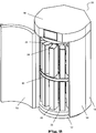
Das technische Problem wird gelöst durch die Anordnung für einen Inkubator für die Zell- und Gewebekultur gemäß Anspruch 1, wobei die Anordnung zur Aufnahme einer Vielzahl von Racks für Kulturgefäßen, besonders Zellkulturplatten wie Multiwellplatten, geeignet und ausgebildet ist. Dabei sind die Racks in einem um die vertikale Längsachse des Inkubators rotierbaren Rack-Träger in Form eines mittigen Trägertellers vertikal angeordnet, und zwar in zumindest zwei übereinander liegenden Stockwerken. Erfindungsgemäß ist der Rack-Träger bevorzugt ausschließlich zwischen diesen Stockwerken angeordnet, wobei die Racks des unteren Stockwerks an diesem mittigen Trägerteller frei hängend arretierbar sind. Die Racks des oberen Stockwerks sind auf diesem mittigen Trägerteller frei stehend arretierbar. So wird das neuartige Rackkarussell gebildet.The technical problem is solved by the arrangement for an incubator for the cell and tissue culture according to claim 1, wherein the arrangement for receiving a plurality of racks for culture vessels, especially cell culture plates such as multiwell plates, is suitable and designed. In this case, the racks are arranged vertically in a rotatable about the vertical axis of the incubator rack carrier in the form of a central carrier plate, in at least two superimposed floors. According to the invention, the rack support is preferably arranged exclusively between these floors, wherein the racks of the lower floor can be freely suspended from this central support plate. The racks of the upper floor are free standing lockable on this central carrier plate. This is how the new rack carousel is made.
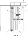
Erfindungsgemäß ist also vorgesehen, dass der Träger der Racks zwischen den beiden Stockwerken, das heißt somit also etwa in der Mitte der Inkubatorkammer angeordnet ist. Dabei ist erfindungsgemäß bevorzugt vorgesehen, dass dieser mittige Trägerteller der einzige Rack-Träger der Anordnung ist und folglich der Inkubator nur diesen einen mittigen Trägerteller zur Aufnahme der oberen und der unteren Racks besitzt. Es sind dabei also keine weiteren Träger, insbesondere nicht am Boden des Inkubators und/oder an der Decke des Inkubators vorgesehen. Da sich erfindungsgemäß so zumindest die unteren Racks von dem mittigen Trägerteller zum Boden der Inkubatorkammer hin frei von Einbauten und Hindernissen, besonders weiteren Halterungen erstrecken können, ist der Boden des Inkubators vorteilhafterweise frei zugänglich. Dies erlaubt zum einen eine deutliche Verbesserung der Reinigbarkeit des Inkubators. Zum anderen wird durch die freie Aufhängung insbesondere der unteren Racks die Gaszirkulation und Wärmekonvektion an den Racks in der Inkubatorkammer signifikant verbessert. The invention thus provides that the support of the racks between the two floors, that is thus thus arranged approximately in the middle of the incubator. In this case, it is preferably provided according to the invention that this central carrier plate is the only rack carrier of the arrangement and consequently the incubator has only this one central carrier plate for receiving the upper and the lower racks. There are thus no further carriers, in particular not provided at the bottom of the incubator and / or on the ceiling of the incubator. Since, according to the invention, at least the lower racks can extend from the central carrier plate to the bottom of the incubator chamber, free of fixtures and obstacles, especially further holders, the bottom of the incubator is advantageously freely accessible. This allows on the one hand a significant improvement in the cleanability of the incubator. On the other hand, the free suspension, in particular of the lower racks, significantly improves the gas circulation and heat convection at the racks in the incubator chamber.
Besonders ist auch vorgesehen, die oberen Racks frei auf die Oberseite dieses mittigen Trägers zu stellen, sodass auch zur Decke des Inkubators hin der Raum frei von Einbauten oder Hindernissen, besonders weiteren Halterungen bleibt, was die Reinigung auch des oberen Bereichs der Inkubatorkammer erleichtert und insgesamt die Zirkulation und Wärmekonvektion im gesamten Inkubatorraum signifikant verbessert. In particular, it is also envisaged to place the upper racks freely on top of this central support, so that the space remains free from obstructions or obstacles, especially other holders, even to the ceiling of the incubator, which facilitates the cleaning of the upper area of the incubator chamber and overall significantly improves circulation and convection throughout the incubator room.
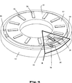
In bevorzugter Ausgestaltung ist dieser, insbesondere einzige, mittige Trägerteller als Vollkreisscheibe ausgebildet und insbesondere über eine vertikale zentrale Achswelle rotierbar gelagert. In einer alternativen und bevorzugten Ausgestaltung ist der Trägerteller als Vollkreisring ausgebildet und, um seinen Mittelpunkt, einer zentralen vertikalen Achse, rotierend gelagert. Dies erfolgt über zumindest einen bevorzugt von radial außen, das heißt von der Gehäusewand des Inkubators feststehenden Lagerarm, der in diesen Ring hereinragt. In einer ersten Variante davon ist der kreisringförmige Trägerteller an dem mindestens einen Lagerarm über ein zentrales Ringlager gelagert. In einer anderen bevorzugten Variante sind zumindest drei vom äußeren Umfang des Kreisrings radial nach zentral verlaufende feststehende Lagerarme vorgesehen, worauf der ringförmige Trägerteller mit einer Lagerfläche oder -schiene aufliegt oder woran er hängt. Dabei ist der Kreisring an den Kontaktstellen zu den Lagerarmen insbesondere über Gleit- oder Rollenlagern gelagert. Alternativ oder zusätzlich sind Kugel-, Magnet und/oder Luftlager vorgesehen. In a preferred embodiment, this, in particular single, central carrier plate is formed as a full-circle disc and rotatably mounted in particular via a vertical central axle shaft. In an alternative and preferred embodiment, the carrier plate is formed as a full circle and, um its center, a central vertical axis, rotatably mounted. This is done via at least one preferably radially outward, that is fixed by the housing wall of the incubator bearing arm, which projects into this ring. In a first variant thereof, the annular carrier plate is mounted on the at least one bearing arm via a central ring bearing. In another preferred variant, at least three radially extending from the outer circumference of the annulus to centrally extending fixed bearing arms, whereupon the annular support plate rests with a bearing surface or rail or what he hangs. In this case, the circular ring is mounted at the contact points to the bearing arms in particular via sliding or roller bearings. Alternatively or additionally, ball, magnet and / or air bearings are provided.
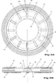
Eine bevorzugte Ausgestaltung sieht bei den rollenden oder gleitenden Lagern, wobei insbesondere der ringförmige Trägerteller mit einer Lagerfläche oder -schiene auf den Gegenlagern der Lagerarme aufliegt, eine mechanische Strukturierung der Roll- oder Gleitfläche an zumindest einem, bevorzugt dem oberen Trägerring des Trägertellers vor, nämlich eine, insbesondere sinusoidale, Höhenprofilierung in Form einer Nockenbahn. Bei Rotation rollt oder gleitet der Trägerteller an den Lagerarmen auf dieser höhenprofilierten Nockenbahn und vollzieht dabei wiederkehrende, periodische Höhenbewegungen in axialer Richtung der Rotation. Deren Amplitude ist primär von dem Ausmaß der Höhenprofilierung, deren Frequenz primär von der Rotationsgeschwindigkeit und der Zahl der Perioden der Nockenprofile der Gleit- oder Rollbahn an dem Trägerteller abhängig. Die Höhenbewegung kann, je nach Anordnung der Lagerpunkte und geometrischer Ausführung der Höhenprofilierung, als im Wesentlichen reine axiale Hubbewegung ausgeführt sein, bevorzugt aber als Taumelbewegung, die sich ergibt, wenn phasengleiche Profilpunkte einer insbesondere sinusoidalen Nockenbahn jeweils phasenversschoben, bevorzugt im Wesentlichen gegenphasig, an den jeweiligen Lagerpunkten der Lagerarme, die auf der Nockenbahn gleiten oder rollen, auflaufen. Eine verschiebliche Position mindestens eines Lagerpunktes erlaubt in einer besonderen Ausgestaltung den Wechsel zwischen reiner Höhenbewegung und Taumelbewegung des Trägertellers. So kann vorteilhaft und automatisch bei der Rotation eine Vibrationsbewegung des Trägertellers erzielt werden, welche sich auf die daran fixierten Racks und auf darin gelagerte Kulturgefäße übertragen kann. Eine solche Bewegung ist insbesondere bei Suspensionskulturen von Vorteil. Eine aktive Dämpfung ist bevorzugt vorgesehen, die ein resonanzbedingtes Aufschaukeln der rotierenden Anordnung, beispielsweise bei kritischen Beladungszuständen oder Rotationsgeschwindigkeiten verhindert. Diese ist bevorzugt durch Dämpfungselemente an den Lagerpunkten der Lagerarme realisiert. A preferred embodiment provides in the rolling or sliding bearings, in particular the annular support plate rests with a bearing surface or rail on the thrust bearings of the bearing arms, a mechanical structuring of the rolling or sliding surface on at least one, preferably the upper support ring of the carrier plate, namely a, in particular sinusoidal, height profiling in the form of a cam track. During rotation, the carrier plate rolls or slides on the bearing arms on this height-profiled cam track and thereby performs recurring, periodic height movements in the axial direction of the rotation. Their amplitude is primarily dependent on the amount of height profiling, the frequency of which depends primarily on the rotational speed and the number of periods of the cam profiles of the slide or runway on the carrier plate. Depending on the arrangement of the bearing points and geometrical design of the height profiling, the height movement can be embodied as a substantially pure axial lifting movement, but preferably as a tumbling motion which results when phase-aligned profile points of a particular sinusoidal cam track are in each case phase-shifted, preferably substantially in phase opposition respective bearing points of the bearing arms, which slide or roll on the cam track accumulate. A displaceable position of at least one bearing point allows in a particular embodiment, the change between pure height movement and wobbling movement of the carrier plate. Thus, a vibration movement of the carrier plate can advantageously and automatically be achieved during rotation, which can be transferred to the fixed thereto racks and culture vessels stored therein. Such a movement is particularly advantageous in suspension cultures. An active damping is preferably provided which prevents resonance-induced rocking of the rotating arrangement, for example in the case of critical loading conditions or rotational speeds. This is preferably realized by damping elements at the bearing points of the bearing arms.
Eine zum Zwecke der mechanischen Bewegung der Kulturgefäße in den Racks zu dieser höhenprofilierten „Berg- und Talbahn“ alternative oder zusätzliche Ausgestaltung sieht vor, dass die Gegenlager in den Lagerarmen, worauf die Lagerflächen des Trägertellers gleiten oder rollen, in den Lagerarmen selbst, insbesondere periodisch, höhenverschoben werden. In einer Variante davon sind in die Lagerarme rotierende exzentrische Nocken eingesetzt, welche die Lagerpunkte wie Stößel periodisch in der Auflagehöhe verändern. Eine alternative Variante ist die Höhenverschiebung der Lagerpunkte in den Lagerarmen durch pneumatische Aktoren oder hydraulische Aktoren. Letztere erlauben insbesondere auch aperiodische Bewegungen, vor allem eine gesteuerte und insbesondere amplitudenund/oder frequenzgeregelte Vibration, die sich an der aktuellen Beladung der Racks an dem Trägerteller und damit an dem zum bewegenden Masse-Feder-System orientiert. A for the purpose of mechanical movement of the culture vessels in the racks to this height-profiled "up and down" alternative or additional embodiment provides that the anvil in the bearing arms, whereupon the bearing surfaces of the carrier plate slide or roll in the bearing arms themselves, in particular periodically to be offset in height. In a variant thereof, rotating eccentric cams are used in the bearing arms, which periodically change the bearing points such as plungers in the support height. An alternative variant is the height displacement of the bearing points in the bearing arms by pneumatic actuators or hydraulic actuators. The latter also allow in particular aperiodic movements, especially a controlled and in particular amplitude and / or frequency-controlled vibration, which is based on the current loading of the racks on the carrier plate and thus on the moving mass-spring system.
Die Ausgestaltung des Trägertellers in Form eines Kreisrings ermöglicht einen zentralen vertikalen Kamin, der die Gaszirkulation und den Wärmetransport wesentlich verbessert. Das Gasmedium wird in dem zentralen Kamin zwangsgeführt. Vorteilhaft ist dabei besonders, dass am Boden des Inkubatorraums keine Einbauten vorhanden sein brauchen, die dem Entstehen dieser Kaminwirkung entgegenwirken, da die unteren Racks allein an dem mittigen Tellerring hängen und nach unten hin frei bleiben können. The design of the carrier plate in the form of a circular ring allows a central vertical chimney, which significantly improves the gas circulation and the heat transfer. The gas medium is forcibly guided in the central chimney. It is particularly advantageous that no internals need be present at the bottom of the incubator, which counteract the emergence of this chimney effect, since the lower racks hang alone on the central plate ring and can remain free at the bottom.
Zum Antrieb des Trägers, das heißt zu dessen aktiver Rotation, ist in einer ersten Variante an dem äußeren Umfang des scheiben- oder ringförmigen Trägertellers, besonders an dem inneren oder an dem äußeren Rand des Kreisrings, ein Zahnkranz ausgebildet, der mit mindestens einem Stirnrad, welches wiederrum motorisch antreibbar ist, in Eingriff steht. Der motorische Antrieb des oder der Stirnräder erfolgt bevorzugt von außerhalb der Inkubatorkammer, wobei die vertikale oder horizontale Stirnradwelle durch die Inkubatorgehäusewand durchtritt. Dies erleichtert zusätzlich die Reinigung und verbessert die Betriebssicherheit des Inkubators. To drive the carrier, that is to its active rotation, in a first variant on the outer circumference of the disc or annular carrier plate, particularly at the inner or at the outer edge of the annulus, a sprocket formed with at least one spur gear, which in turn is driven by a motor, is engaged. The motor drive of the spur gear or wheels preferably takes place from outside the incubator chamber, the vertical or horizontal spur gear shaft passing through the incubator housing wall. This additionally facilitates cleaning and improves the operational safety of the incubator.
Alternativ ist der Trägerteller über Reibrad, Riemen oder Kette angetrieben. Alternativ ist auch ein Linearmotorantrieb.Alternatively, the carrier plate is driven by a friction wheel, belt or chain. Alternatively, a linear motor drive.
In einer alternativen Variante des Antriebs sind der Trägerteller sowie die Lagerarme an den Lagerflächen mit elektromechanischen Wirkelementen zur Ausbildung eines Linearmotorantriebs ausgestattet. Diese umfassen in einer bevorzugten Ausgestaltung sektorierte Permanentmagnete auf Seiten des rotierenden Trägertellers und, insbesondere gas- und flüssigkeitsdicht vergossene Elektromagnetspulen auf Seiten der feststehenden Lagerarme. Durch entsprechende elektrische Ansteuerung der Magnetspulen ist eine kontaktlose und insbesondere wartungsfreie elektromotorische Rotation des Trägertellers möglich. In an alternative variant of the drive, the carrier plate and the bearing arms are equipped on the bearing surfaces with electromechanical active elements for forming a linear motor drive. In a preferred embodiment, these comprise sectored permanent magnets on sides the rotating carrier plate and, in particular gas- and liquid-tight encapsulated electromagnetic coils on the side of the fixed bearing arms. By appropriate electrical control of the magnetic coils, a contactless and, in particular, maintenance-free electromotive rotation of the carrier plate is possible.
In einer bevorzugten Ausgestaltung des mittigen Trägertellers ist dieser als Doppelscheibe, insbesondere als Doppelring mit zwei übereinander liegenden zueinander beabstandeten Kreisringen ausgebildet. Diese stehen insbesondere im Bereich des inneren Umfangs der Kreisringe über Koppelelemente miteinander mechanisch fest in Verbindung und bilden so zusammen den rotierbaren Trägerteller. Im Bereich des mittleren bis äußeren Umfangs der beiden Kreisringe greift zwischen diese von radial der mindestens eine feststehende Lagerarm ein, sodass zwei kreisringförmige Tellerflächen, jeweils oberhalb und unterhalb dieses Lagerarms gebildet werden. Die Tellerflächen des Trägertellers weisen jeweils Arretierelemente auf, die mit einem Rack in bevorzugt formschlüssigen Eingriff gebracht werden können. In die untere Tellerfläche des mittigen Trägertellers können die unteren Racks eingehängt werden; in die obere Tellerfläche oberen Kreisring des mittigen Trägertellers können die oberen Racks eingesetzt werden. In a preferred embodiment of the central support plate this is formed as a double disc, in particular as a double ring with two superimposed spaced circular rings. These are mechanically fixed in particular in the region of the inner circumference of the circular rings via coupling elements together and thus together form the rotatable carrier plate. In the region of the middle to outer circumference of the two circular rings engages between them from the radially at least one fixed bearing arm, so that two annular disc surfaces, respectively above and below this bearing arm are formed. The plate surfaces of the carrier plate each have locking elements, which can be brought into a preferably positive engagement with a rack. In the lower plate surface of the central carrier plate, the lower racks can be hung; in the upper plate surface upper circular ring of the central carrier plate, the upper racks can be used.
Diese besondere Konstruktion vermeidet weitere komplexe Einbauten und reduziert den Rackkarussellaufbau als solchen auf ein Minimum. This special construction avoids further complex installations and reduces the rack carousel construction as such to a minimum.
Alternativ oder zusätzlich ist vorgesehen, die beiden gekoppelten Trägertellerflächen unabhängig voneinander drehbar zu gestalten. Dies könnte ein einfaches und schnelles Umlagern oder Auslagern der in den anhängenden Racks gelagerten Kulturgefäße oder Kulturplatten erleichtern: Beim Umlagern von dem oberen Teller auf den unteren können mit den beiden getrennt drehbaren Tellerringen des Trägertellers günstige Positionen übereinander gebracht werden, sodass nach Aufnahme der Platte aus einem oberen Rack ein Roboterarm nur eine Z-Bewegung durchführen muss, um diese Platte in ein – zum Bespiel durch unabhängiges Drehen des unteren Tellers – unmittelbar darunter positioniertes unteres Rack zu befördern. Entsprechend können beim Auslagern oder Beschicken obere und untere Racks unabhängig voneinander so positioniert werden, dass der Roboterarm allein durch Ausführen einer Z-Bewegung die gewünschten Zellkulturgefäße oder Platten an den Übergabeport transportieren kann. Spezifisch ist in einer bevorzugten Ausführungsform vorgesehen, dass der gesamte Trägerteller auf Lagerarmen aufliegt oder an diesen hängt und damit wie hierin beschrieben drehbar ist, aber die Kopplung zwischen oberer und unterer Trägerfläche nicht starr, sondern selbst, beispielsweise durch ein Ringlager, ausgestaltet ist, sodass innerhalb des an sich gelagerten Trägertellers die beiden oberen und unteren Trägerflächen gegeneinander verdrehbar sind. In einer alternativen Ausgestaltung sind obere und untere Trägerfläche des Trägertellers jeweils separat an dem mindestens einen gemeinsamen Lagerarm drehbar gelagert. Alternatively or additionally, it is provided to make the two coupled carrier plate surfaces independently of each other rotatable. This could facilitate a simple and quick relocation or outsourcing of stored in the attached racks culture vessels or culture plates: When moving from the upper plate to the lower can be placed on top of each other with the two separately rotatable plate rings of the carrier plate favorable positions, so after receiving the plate an upper rack, a robot arm must perform only a Z-movement, in order to move this plate in a - for example, by independently turning the lower plate - just below positioned lower rack. Accordingly, when retrieving or loading, upper and lower racks can be positioned independently of each other so that the robot arm alone can carry the desired cell culture vessels or plates to the transfer port by performing a Z-movement. Specifically, it is provided in a preferred embodiment that the entire carrier plate rests on bearing arms or hanging on this and thus rotatable as described herein, but the coupling between the upper and lower support surface is not rigid, but even, for example by a ring bearing, designed so within the carrier plate mounted on itself, the two upper and lower support surfaces are rotated against each other. In an alternative embodiment, upper and lower carrier surface of the carrier plate are each mounted separately rotatably on the at least one common bearing arm.
Weiterer Gegenstand der Erfindung ist auch der Inkubator selbst, welcher die hierin beschriebene erfindungsgemäße Anordnung eines Rackkarussells enthält. Eine bevorzugte spezifische Ausführung dieses Inkubators sieht vor, dass die innere Wand der Inkubatorkammer über den gesamten Umfang des kreis- oder kreisringförmigen Trägers im Querschnitt möglichst eng anliegt, um möglichst wenig Totraum zwischen Rackkarussell und Gehäusewand im Inkubatorraum zu erzeugen. Die Vermeidung von Toträumen im Inkubatorraum im Bereich des Umfangs des Rackkarussells verbessert die Zirkulation von Gas sowie die Wärmezirkulation innerhalb der Racks. Ein strömungstechnischer „Nebenschluss“ durch einen Pfad, welcher zwischen dem äußeren Umfang des Rackkarussells und der inneren Wand des Inkubatorraums gebildet werden würde, wird minimiert. Gleichzeitig erlaubt die bevorzugte ringförmige Gestaltung des mittigen Trägers der Anordnung einen zentralen „Kamin“ zur effizienten Strömungsleitung, das heißt zur Zirkulation und Gasaustausch. Im bestückten Zustand der Anordnung wird ein Rackkarussell gebildet, welches eine im Wesentlichen zylindrische Außenform hat. Folglich ist bevorzugt, die innere Wand des Inkubatorraums an die zylindrische Form des Rackkarussells anzunähern. In einer ersten Variante weist daher das Inkubatorgehäuse einen kreisrunden Querschnitt auf. Um eine mechanische Ankopplung und Trägerung von Anbauteilen, beispielsweise Roboterarmen und Übergabeschächten in oder an dem Inkubatorgehäuse zu ermöglichen und insbesondere mechanische Schnittstellen zu benachbarten Apparaten einer automatischen Handhabungskette zu schaffen, ist bevorzugt vorgesehen, dass zumindest eine plane Fase an dem ansonsten zylindrischen Inkubatorgehäuse ausgebildet ist. In einer Variante dieser Ausgestaltung ist zumindest der hintere und seitliche Abschnitt des Inkubatorgehäuses im Querschnitt als Vieleck, insbesondere als halben Achteck, und der vordere Abschnitt des Inkubatorgehäuses im Querschnitt als Halbkreis oder als im Querschnitt als Vieleck für eine Türe ausgebildet. Another object of the invention is also the incubator itself, which contains the inventive arrangement of a rack carousel described herein. A preferred specific embodiment of this incubator provides that the inner wall of the incubator over the entire circumference of the circular or annular support in the cross-section as close as possible to create as little dead space between rack carousel and housing wall in the incubator. Avoiding dead spaces in the incubator space around the circumference of the rack carousel improves the circulation of gas and the circulation of heat within the racks. A fluidic "shunt" through a path that would be formed between the outer circumference of the rack carousel and the inner wall of the incubator chamber is minimized. At the same time, the preferred annular design of the central support of the assembly allows a central "chimney" for efficient flow conduction, that is, for circulation and gas exchange. In the assembled state of the arrangement, a rack carousel is formed, which has a substantially cylindrical outer shape. Consequently, it is preferred to approximate the inner wall of the incubator chamber to the cylindrical shape of the rack carousel. In a first variant, therefore, the incubator has a circular cross-section. In order to enable a mechanical coupling and support of attachments, such as robot arms and transfer shafts in or on the incubator and in particular to provide mechanical interfaces to adjacent apparatuses of an automatic handling chain, it is preferably provided that at least one flat bevel is formed on the otherwise cylindrical incubator housing. In a variant of this embodiment, at least the rear and side portion of the incubator in cross section as a polygon, in particular as a half octagon, and the front portion of the incubator in cross section as a semicircle or as a cross-section as a polygon for a door.
Die Erfindung wird durch die Figuren spezifischer Ausführungsbeispiele und deren nachfolgender Beschreibung näher erläutert, ohne dass diese beschränkend zu verstehen wären. The invention is explained in more detail by the figures of specific embodiments and their subsequent description, without these being limiting.
Claims (10)
Priority Applications (1)
| Application Number | Priority Date | Filing Date | Title |
|---|---|---|---|
| DE102016208552.2A DE102016208552B3 (en) | 2016-05-18 | 2016-05-18 | Automatable incubator for cell and tissue culture |
Applications Claiming Priority (1)
| Application Number | Priority Date | Filing Date | Title |
|---|---|---|---|
| DE102016208552.2A DE102016208552B3 (en) | 2016-05-18 | 2016-05-18 | Automatable incubator for cell and tissue culture |
Publications (1)
| Publication Number | Publication Date |
|---|---|
| DE102016208552B3 true DE102016208552B3 (en) | 2017-04-06 |
Family
ID=58355835
Family Applications (1)
| Application Number | Title | Priority Date | Filing Date |
|---|---|---|---|
| DE102016208552.2A Active DE102016208552B3 (en) | 2016-05-18 | 2016-05-18 | Automatable incubator for cell and tissue culture |
Country Status (1)
| Country | Link |
|---|---|
| DE (1) | DE102016208552B3 (en) |
Cited By (10)
| Publication number | Priority date | Publication date | Assignee | Title |
|---|---|---|---|---|
| CN110042056A (en) * | 2018-01-16 | 2019-07-23 | 武汉艾德士生物科技有限公司 | A kind of multi-functional cell incubator |
| CN111172032A (en) * | 2020-02-19 | 2020-05-19 | 海口健康岛生物科技有限公司 | Automatic incubator for living cells |
| CN113544253A (en) * | 2019-03-05 | 2021-10-22 | 发那科株式会社 | Cell manufacturing system |
| CN114672416A (en) * | 2022-04-11 | 2022-06-28 | 广东省人民医院 | A tumor cell culture device |
| US11959060B1 (en) | 2019-05-17 | 2024-04-16 | Humacyte, Inc. | Fluid systems, apparatuses, devices and methods of management thereof for cultivating tissue |
| CN118291229A (en) * | 2024-03-04 | 2024-07-05 | 青岛海尔生物医疗股份有限公司 | Carrying device and AGV device for sedimentation bacteria culture dish |
| US12104148B1 (en) | 2019-05-17 | 2024-10-01 | Humacyte, Inc. | System, apparatuses, devices and methods for straining a cultivated tissue |
| US12195711B1 (en) * | 2019-05-17 | 2025-01-14 | Humacyte, Inc. | Drawer system for cultivating tissue |
| CN120864341A (en) * | 2025-09-25 | 2025-10-31 | 长沙市市政工程有限责任公司 | Tilting construction lifting device and method |
| EP4663743A1 (en) * | 2024-06-14 | 2025-12-17 | Fraunhofer-Gesellschaft zur Förderung der angewandten Forschung e.V. | Modular tray unit and modular unit for incubator, and incubator using it, and incubator |
Citations (1)
| Publication number | Priority date | Publication date | Assignee | Title |
|---|---|---|---|---|
| EP2821477A1 (en) * | 2012-02-29 | 2015-01-07 | JTEC Corporation | Cell culture device having culture medium replacement function |
-
2016
- 2016-05-18 DE DE102016208552.2A patent/DE102016208552B3/en active Active
Patent Citations (1)
| Publication number | Priority date | Publication date | Assignee | Title |
|---|---|---|---|---|
| EP2821477A1 (en) * | 2012-02-29 | 2015-01-07 | JTEC Corporation | Cell culture device having culture medium replacement function |
Cited By (15)
| Publication number | Priority date | Publication date | Assignee | Title |
|---|---|---|---|---|
| CN110042056A (en) * | 2018-01-16 | 2019-07-23 | 武汉艾德士生物科技有限公司 | A kind of multi-functional cell incubator |
| CN113544253B (en) * | 2019-03-05 | 2024-09-06 | 发那科株式会社 | Cell Manufacturing System |
| US12365859B2 (en) | 2019-03-05 | 2025-07-22 | Fanuc Corporation | Cell production system |
| CN113544253A (en) * | 2019-03-05 | 2021-10-22 | 发那科株式会社 | Cell manufacturing system |
| JP7557791B2 (en) | 2019-03-05 | 2024-09-30 | ファナック株式会社 | Cell Manufacturing System |
| JP2022121606A (en) * | 2019-03-05 | 2022-08-19 | ファナック株式会社 | cell manufacturing system |
| EP3936599A4 (en) * | 2019-03-05 | 2023-04-05 | Fanuc Corporation | SYSTEM FOR PRODUCTION OF CELLS |
| US11959060B1 (en) | 2019-05-17 | 2024-04-16 | Humacyte, Inc. | Fluid systems, apparatuses, devices and methods of management thereof for cultivating tissue |
| US12104148B1 (en) | 2019-05-17 | 2024-10-01 | Humacyte, Inc. | System, apparatuses, devices and methods for straining a cultivated tissue |
| US12195711B1 (en) * | 2019-05-17 | 2025-01-14 | Humacyte, Inc. | Drawer system for cultivating tissue |
| CN111172032A (en) * | 2020-02-19 | 2020-05-19 | 海口健康岛生物科技有限公司 | Automatic incubator for living cells |
| CN114672416A (en) * | 2022-04-11 | 2022-06-28 | 广东省人民医院 | A tumor cell culture device |
| CN118291229A (en) * | 2024-03-04 | 2024-07-05 | 青岛海尔生物医疗股份有限公司 | Carrying device and AGV device for sedimentation bacteria culture dish |
| EP4663743A1 (en) * | 2024-06-14 | 2025-12-17 | Fraunhofer-Gesellschaft zur Förderung der angewandten Forschung e.V. | Modular tray unit and modular unit for incubator, and incubator using it, and incubator |
| CN120864341A (en) * | 2025-09-25 | 2025-10-31 | 长沙市市政工程有限责任公司 | Tilting construction lifting device and method |
Similar Documents
| Publication | Publication Date | Title |
|---|---|---|
| DE102016208552B3 (en) | Automatable incubator for cell and tissue culture | |
| EP1441026B1 (en) | Automatic storage system and climatic cabinet with automatic storage system | |
| EP0853657B1 (en) | Storage device for objects, storage station, and air-conditioned cabinet | |
| EP2848383A1 (en) | Transport device and method for transporting plastic containers or preforms | |
| EP2489465B1 (en) | Honing machine with device for mechanical surface processing of workpieces | |
| DD144897A5 (en) | SUPPORT FOR BOTTLE TURNERS OF A LABELING MACHINE | |
| EP0517652A1 (en) | Tools and/or workpieces magazine | |
| EP0517651B1 (en) | Manufacturing installation | |
| DE102013013978B4 (en) | Tool terminal with concentric sheet metal walls | |
| EP0518109A1 (en) | Apparatus for vacuum treatment | |
| EP1836292B1 (en) | Automatic storing device and climatic chamber for laboratory equipment | |
| DE102008032806A1 (en) | Apparatus for producing hollow bodies from thermoplastically deformable plastic films | |
| DE102012221804B4 (en) | Transport device and method for transporting plastic containers or preforms | |
| EP1784651A1 (en) | Unit for processing microbiological samples | |
| EP2645035A1 (en) | Rotating drum oven | |
| EP2093038B1 (en) | Rotation molding assembly | |
| DE10348281B4 (en) | Vacuum treatment plant for flat rectangular or square substrates | |
| EP3170775A1 (en) | Intermediate storage for piece goods | |
| EP2565292B1 (en) | Apparatus and method for coating substrates using the eb/pvd process | |
| EP3189888B1 (en) | Mixing device | |
| EP0302167A2 (en) | Apparatus for producing layers on substrates with a homogeneous profile thickness by sputtering | |
| DE102014001934A1 (en) | Cleaning system with a treatment chamber | |
| DD220542A1 (en) | TOOL MEMORY FOR AUTOMATIC TOOL CHANGE SETUP | |
| DE202015103526U1 (en) | magazine | |
| DE102014226822A1 (en) | Pivoting device, in particular for a sorting trolley of a sorting device |
Legal Events
| Date | Code | Title | Description |
|---|---|---|---|
| R012 | Request for examination validly filed | ||
| R016 | Response to examination communication | ||
| R018 | Grant decision by examination section/examining division | ||
| R020 | Patent grant now final | ||
| R084 | Declaration of willingness to licence | ||
| R082 | Change of representative |