Die Erfindung betrifft eine Projektionsoptik zur Abbildung eines Objektfeldes in ein Bildfeld. Ferner betrifft die Erfindung ein optisches System mit einer derartigen Projektionsoptik, eine Projektionsbelichtungsanlage mit einem derartigen optischen System, ein Verfahren zur Herstellung eines mikro- bzw. nanostrukturierten Bauteils mit einer derartigen Projektionsbelichtungsanlage sowie ein mit diesem Verfahren hergestelltes mikro- bzw. nanostrukturiertes Bauelement.The invention relates to a projection optics for imaging an object field in an image field. The invention further relates to an optical system having such a projection optical system, to a projection exposure apparatus comprising such an optical system, to a method for producing a microstructured or nanostructured component having such a projection exposure apparatus, and to a microstructured or nanostructured component produced by this method.
Projektionsoptiken der eingangs genannten Art sind bekannt aus der DE 10 2012 202 675 A1 , der DE 10 2009 011 328 A1 , der US 8 027 022 B2 und der US 6 577 443 B2 . Eine Beleuchtungsoptik für eine Projektionsbelichtungsanlage ist bekannt aus der DE 10 2009 045 096 A1 . Projection optics of the type mentioned are known from the DE 10 2012 202 675 A1 , of the DE 10 2009 011 328 A1 , of the US Pat. No. 8,027,022 B2 and the US Pat. No. 6,577,443 B2 , An illumination optics for a projection exposure apparatus is known from the DE 10 2009 045 096 A1 ,
Es ist eine Aufgabe der vorliegenden Erfindung, eine Projektionsoptik der eingangs genannten Art derart weiterzubilden, dass ein gut korrigiertes abbildbares Feld bei gleichzeitig hohem Abbildungslicht-Durchsatz resultiert. It is an object of the present invention to further develop a projection optics of the type mentioned at the outset such that a well-corrected imageable field results while at the same time having high imaging light throughput.
Diese Aufgabe ist erfindungsgemäß gelöst durch eine Projektionsoptik mit den im Anspruch 1 angegebenen Merkmalen und durch eine EUV-Projektionsoptik mit den im Anspruch 10 angegebenen Merkmalen. This object is achieved by a projection optics with the features specified in claim 1 and by an EUV projection optics with the features specified in claim 10.
Erfindungsgemäß wurde erkannt, dass zwei direkt hintereinander angeordnete Spiegel für streifenden Einfall innerhalb der Projektionsoptik zur Möglichkeit führen, eine Projektionsoptik mit hohem und über das gesamte abzubildende Feld gleichmäßigem Abbildungslicht-Durchsatz zu gestalten, wobei gleichzeitig auch über die Spiegel mit streifenden Einfall Freiheitsgrade zur Abbildungskorrektur im Bildfeld gegeben sind. According to the invention, it has been recognized that two grazing incidence mirrors arranged directly behind one another within the projection optics make it possible to design a projection optics with uniform image light throughput at a high and over the entire field to be imaged, while at the same time providing degrees of freedom for image correction in the grazing incidence mirror Image field are given.
Die Spiegel der Projektionsoptik können die Abbildungslicht-Reflektivität steigernde Beschichtungen tragen. Für diese Beschichtungen können als Beschichtungsmaterialien Ruthenium und/oder Molybdän zum Einsatz kommen.The mirrors of the projection optics may carry the imaging light reflectivity enhancing coatings. For these coatings, ruthenium and / or molybdenum can be used as coating materials.
Die Spiegel für streifenden Einfall können eine Reflektivität haben, die im Bereich zwischen 75 und 95 % liegt und die insbesondere mindestens 80 % betragen kann. Die Spiegel für streifenden Einfall können eine Reflektivität haben, die linear vom Einfallswinkel abhängt. Eine solche lineare Abhängigkeit lässt sich durch Einsatz mindestens eines weiteren Spiegels für streifenden Einfall, der ebenfalls eine entsprechende lineare Abhängigkeit der Reflektivität vom Einfallswinkel aufweist, kompensieren. Die Projektionsoptik ist geeignet für EUV-Wellenlängen des Abbildungslichts, besonders im Bereich zwischen 5 nm und 30 nm. Der Einfallswinkel des Abbildungslichts auf den Spiegeln für streifenden Einfall kann größer sein als 65 °, kann größer sein als 70 °, kann größer sein als 72 °, kann größer sein als 75 °, kann größer sein als 80 ° oder kann auch größer sein als 85 °. The grazing incidence mirrors may have a reflectivity which is in the range between 75 and 95% and in particular may be at least 80%. The grazing incidence mirrors can have a reflectivity that depends linearly on the angle of incidence. Such a linear dependence can be compensated by using at least one further grazing incidence mirror which likewise has a corresponding linear dependence of the reflectivity on the angle of incidence. The projection optics are suitable for EUV wavelengths of the imaging light, especially in the range between 5 nm and 30 nm. The incident angle of the imaging light on the grazing incidence mirrors may be greater than 65 °, may be greater than 70 °, may be greater than 72 °, may be greater than 75 °, may be greater than 80 ° or may be greater than 85 °.
Die Projektionsoptik kann zur Abbildung eines Abschnitts eines reflektierenden Retikels ausgeführt sein. Hierzu kann ein Hauptstrahl eines zentralen Objektfeldpunktes mit einer Normalen auf die Objektebene einen Winkel einschließen, der größer ist als 3 ° und beispielsweise 5,5 ° beträgt. The projection optics can be designed to image a section of a reflective reticle. For this purpose, a main ray of a central object field point with a normal to the object plane include an angle which is greater than 3 ° and, for example, 5.5 °.
Bei einem der mindestens zwei Spiegel für streifenden Einfall kann es sich um den ersten Spiegel der Projektionsoptik im Abbildungsstrahlengang nach dem Objektfeld handeln. Die Spiegel für streifenden Einfall können Reflexionsflächen haben, die von einer ebenen Fläche abweichen und können insbesondere eine abbildungsfehlerkorrigierende Flächenform haben. Die Reflexionsflächen der Spiegel für streifenden Einfall können als asphärische Flächen oder auch als Freiformflächen ohne Rotationssymmetrie ausgeführt sein.One of the at least two grazing incidence mirrors may be the first mirror of the projection optics in the imaging beam path after the object field. The grazing incidence mirrors may have reflection surfaces that deviate from a flat surface and, in particular, may have an aberration correcting surface shape. The reflection surfaces of the grazing incidence mirrors can be embodied as aspherical surfaces or as freeform surfaces without rotational symmetry.
Eine Zwischenbildebene kann im Bereich einer Reflexion an einem Spiegel für streifenden Einfall angeordnet sein. Dies führt zu einer vorteilhaften Einengung eines Abbildungslichtbündels im Bereich des Spiegels für streifenden Einfall und vermeidet somit, dass dieser eine unerwünscht große Reflexionsfläche haben muss.An intermediate image plane may be located in the region of a reflection on a grazing incidence mirror. This leads to an advantageous narrowing of an imaging light beam in the region of the grazing incidence mirror and thus avoids that it must have an undesirably large reflection surface.
Die Projektionsoptik kann als katoptrische Optik ausgeführt sein.The projection optics can be designed as catoptric optics.
Die Projektionsoptik kann mindestens einen Spiegel mit einer Durchtrittsöffnung für das Beleuchtungslicht aufweisen. Die Projektionsoptik kann als obskurierte Optik ausgeführt sein. The projection optics can have at least one mirror with a passage opening for the illumination light. The projection optics can be designed as obscured optics.
Alternativ kann die Projektionsoptik auch so ausgeführt sein, dass die Reflexionsflächen aller Spiegel der Projektionsoptik durchgehend genutzt sind. Die Projektionsoptik kann als nicht-obskurierte Optik ausgeführt sein. Alternatively, the projection optics can also be designed so that the reflection surfaces of all mirrors of the projection optics are used continuously. The projection optics can be designed as non-obscured optics.
Ein x/y-Aspektverhältnis einer optisch mit Beleuchtungslicht beaufschlagten, also genutzten Reflexionsfläche mindestens eines Spiegels der Projektionsoptik kann kleiner sein als 1, kann kleiner sein als 0,8, kann 0,7 betragen, kann kleiner sein als 0,7, kann kleiner sein als 0,6 und kann 0,5 betragen. Die Koordinate y liegt dabei in einer Einfallsebene des jeweils betrachteten Spiegels. Die Koordinate x liegt senkrecht zur Einfallsebene des jeweils betrachteten Spiegels. Längs der Koordinate y kann auch eine Scanrichtung verlaufen, in der ein abzubildendes Objekt und/oder ein Substrat, auf welches abgebildet wird, verlagert wird. An x / y aspect ratio of an optically illuminated illumination surface of at least one mirror of the projection optics can be smaller than 1, can be smaller than 0.8, can be 0.7, can be smaller than 0.7, can be smaller be 0.6 and can be 0.5. The coordinate y lies in an incidence plane of the mirror under consideration. The coordinate x is perpendicular to the plane of incidence of each considered mirror. A scan direction can also run along the coordinate y, in which an object to be imaged and / or a substrate to be imaged is displaced.
Ein x/y-Aspektverhältnis einer optisch mit Beleuchtungslicht beaufschlagten, also genutzten Reflexionsfläche mindestens eines Spiegels der Projektionsoptik kann größer sein als 1, kann 2 betragen, kann größer sein als 2, kann 2,5 betragen, kann größer sein als 2,5, kann größer sein als 3, kann größer sein als 4, kann größer sein als 5, kann größer sein als 6, kann 7,5 betragen, kann größer sein als 10 und kann 15 betragen. An x / y aspect ratio of an optically illuminated illumination surface of at least one mirror of the projection optics may be greater than 1, may be 2, may be greater than 2, may be 2.5, may be greater than 2.5, may be greater than 3, may be greater than 4, may be greater than 5, may be greater than 6, may be 7.5, may be greater than 10, and may be 15.
Die Projektionsoptik kann eine Spiegelabfolge aufweisen, bei der neben mindestens einem GI-Spiegelpaar, also zwei im Strahlengange direkt hintereinander angeordneten Spiegeln für streifenden Einfall, auch ein einzelner GI-Spiegel vorliegt. Die Projektionsoptik kann drei aufeinander folgende GI-Spiegel aufweisen. The projection optics can have a mirror sequence in which, in addition to at least one pair of GI mirrors, that is to say two mirrors arranged in the beam path directly one behind the other, there is also a single GI mirror. The projection optics can have three consecutive GI mirrors.
Die Projektionsoptik kann mindestens einen Spiegel aufweisen, der als Sattelfläche ausgeführt ist, also in einer Ebene eine positive und in einer hierzu senkrechten Ebene eine negative Brechkraft aufweist. Die Projektionsoptik kann mehrere solche Sattelflächen-Spiegel aufweisen. The projection optics can have at least one mirror which is designed as a saddle surface, that is to say has a positive refractive power in one plane and a negative refractive power in a plane perpendicular thereto. The projection optics may have a plurality of such saddle surface mirrors.
Genau zwei Spiegel für streifenden Einfall nach Anspruch 2 haben sich bei der Projektionsoptik als besonders geeignet herausgestellt.Exactly two mirrors for grazing incidence according to claim 2 have been found in the projection optics to be particularly suitable.
Ein Winkel zwischen einer Objektebene und einer Bildebene nach Anspruch 3 ermöglicht eine besonders kompakte Führung des Abbildungslicht-Strahlengangs bzw. Abbildungsstrahlengangs. Dieser Winkel kann größer sein als 1 °, kann größer sein als 2 °, kann größer sein als 3 °, kann größer sein als 5 °, kann größer sein als 7 °, kann größer sein als 10 °, kann größer sein als 20 °, kann größer sein als 30 ° und kann 39 ° betragen.An angle between an object plane and an image plane according to claim 3 enables a particularly compact guidance of the imaging light beam path or imaging beam path. This angle can be greater than 1 °, greater than 2 °, greater than 3 °, greater than 5 °, greater than 7 °, greater than 10 °, greater than 20 ° , can be greater than 30 ° and can be 39 °.
Auch genau vier Spiegel für streifenden Einfall nach Anspruch 4 haben sich als besonders geeignet herausgestellt. Also exactly four grazing incidence mirrors according to claim 4 have been found to be particularly suitable.
Eine paarweise Anordnung der Spiegel für streifenden Einfall nach Anspruch 5 hat sich zur Kompensation einer einfallswinkelabhängigen Reflexion als geeignet herausgestellt. Zwischen den Paaren der Spiegel für streifenden Einfall kann mindestens ein Spiegel für normalen Einfall liegen. Die Paare der Spiegel für streifenden Einfall können so angeordnet sein, dass sich eine umlenkende Wirkung der beiden nacheinander angeordneten Spiegel summiert, dass sich die Ausfallswinkel also aufaddieren. Eine solche Ausführung ermöglicht eine Kompensation einer einfallswinkelabhängigen Reflektivität auf den Spiegeln für streifenden Einfall. Alternativ ist es möglich, einem Spiegel für streifenden Einfall einen Kompensations-Spiegel für streifenden Einfall an anderer Stelle im Strahlengang des Abbildungslichts durch die Projektionsoptik zuzuordnen, wobei Einzelstrahlen, die auf dem Spiegel für streifenden Einfall mit größerem Einfallswinkel auftreffen, auf dem Kompensations-Spiegel entsprechend mit kleinerem Einfallswinkel auftreffen und umgekehrt. Zwischen einem Spiegel mit streifendem Einfall und dem ihm zugeordneten Kompensations-Spiegel kann ein weiterer Spiegel für streifenden Einfall und/oder ein Spiegel für normalen Einfall angeordnet sein. Soweit mehr als zwei Spiegel für streifenden Einfall bei der Projektionsoptik vorgesehen sind, kann die Kompensationswirkung eines Kompensations-Spiegels auch für mehr als einen der anderen Spiegel für streifenden Einfall gelten. Es ist beispielsweise also möglich, bei drei Spiegeln für streifenden Einfall einen Kompensationsspiegel für streifenden Einfall vorzusehen, der für zwei weitere Spiegel für streifenden Einfall die Einfallswinkelabhängigkeit der Reflexion kompensiert.A paired arrangement of the grazing incidence mirrors of claim 5 has been found to be suitable for compensating incident angle-dependent reflection. Between the pairs of grazing incidence mirrors, there may be at least one normal incidence mirror. The pairs of grazing incidence mirrors may be arranged so that a deflecting effect of the two consecutively arranged mirrors adds up, so that the angles of incidence add up. Such an embodiment allows for compensation of incident angle-dependent reflectivity on the grazing incidence mirrors. Alternatively, it is possible to associate a grazing incidence mirror with a grazing incidence mirror elsewhere in the beam path of the imaging light through the projection optics, with individual rays impinging on the grazing incidence mirror with a larger angle of incidence corresponding to the compensation mirror hit with a smaller angle of incidence and vice versa. Between a grazing incidence mirror and the compensation mirror associated therewith, another grazing incidence mirror and / or normal incidence mirror may be arranged. As far as more than two grazing incidence mirrors are provided in the projection optics, the compensation effect of a compensation mirror may also apply to more than one of the other grazing incidence mirrors. It is thus possible, for example, to provide a grazing incidence compensation mirror in three grazing incidence mirrors which compensates the incidence angle dependence of the reflection for two further grazing incidence mirrors.
Eine Ausführung nach Anspruch 6 hat sich zur Erfüllung von Randbedingungen, die an eine Projektionsoptik gestellt werden, für besonders geeignet herausgestellt. Die mindestens zwei Spiegel für normalen Einfall können mit einem Einfallswinkel des Abbildungslichts beaufschlagt sein, der kleiner ist als 40 °, der kleiner ist als 35 °, der kleiner ist als 30 °, der kleiner ist als 25 °, der kleiner ist als 20 ° und der auch noch kleiner sein kann. An embodiment according to claim 6 has been found to be particularly suitable for the fulfillment of boundary conditions, which are placed on a projection optics. The at least two normal incidence mirrors may be exposed to an incident angle of the imaging light which is less than 40 °, which is smaller than 35 °, which is smaller than 30 °, which is smaller than 25 °, which is smaller than 20 ° and that can be even smaller.
Vier Spiegel für normalen Einfall nach Anspruch 7 führen zur Möglichkeit einer besonders gut abbildungskorrigierten Projektionsoptik.Four mirrors for normal incidence according to claim 7 lead to the possibility of a particularly well-corrected image projection optics.
Eine bildseitige numerische Apertur der Projektionsoptik kann mindestens 0,4 oder 0,5 oder 0.6 betragen. Eine derartige Projektionsoptik ermöglicht eine besonders hohe Auflösung. A picture-side numerical aperture of the projection optics may be at least 0.4 or 0.5 or 0.6. Such a projection optics enables a particularly high resolution.
Eine Gesamt-Reflektivität der Projektionsoptik nach Anspruch 8 kann 9,75 % betragen, kann größer sein als 10 %, kann größer sein als 11 %, kann 11,97 % betragen, kann größer sein als 12 % und kann insbesondere 12,2 % betragen. Auch größere Gesamt-Reflektivitäten sind möglich, insbesondere je nach Ausführung reflexionserhöhender Beschichtungen auf den Spiegeln. A total reflectivity of the projection optics according to claim 8 may be 9.75%, may be greater than 10%, may be greater than 11%, may be 11.97%, may be greater than 12% and may in particular 12.2%. be. Even larger total reflectivities are possible, especially depending on the design of reflection-enhancing coatings on the mirrors.
Eine EUV-Projektionsoptik nach Anspruch 9 hat gleichzeitig eine hohe Strukturauflösung und einen hohen Durchsatz für das EUV-Abbildungslicht. Bei der Projektion geht also wenig Nutzlicht verloren, was wiederum eine Belichtungsdauer verkürzt und somit den Wafer-Durchsatz einer Projektionsbelichtungsanlage, die mit einer derartigen EUV-Projektionsoptik ausgerüstet ist, erhöht. Die Gesamt-Reflektivität kann größer sein als 8 %, kann größer sein als 9 %, kann 10 % betragen oder kann sogar noch größer sein.An EUV projection optical system according to claim 9 simultaneously has a high structural resolution and a high throughput for the EUV imaging light. In the projection, therefore, little useful light is lost, which in turn shortens an exposure time and thus increases the wafer throughput of a projection exposure apparatus equipped with such EUV projection optics. The total reflectivity may be greater than 8%, may be greater than 9%, may be 10%, or even greater.
Eine nach Anspruch 10 als anamorphotische Optik ausgeführte Projektionsoptik hat sich als besonders vorteilhaft herausgestellt. A projection optics designed according to claim 10 as anamorphic optics has been found to be particularly advantageous.
Die anamorphotische Optik hat für unterschiedliche Feldkoordinaten, insbesondere für aufeinander senkrecht stehende Feldkoordinaten unterschiedliche Abbildungsmaßstäbe. Als Abbildungsmaßstab wird dabei ein absoluter Verkleinerungsfaktor der Projektionsoptik bezeichnet. Eine beispielsweise um einen Faktor 4 verkleinernde Projektionsoptik hat entsprechend einen Abbildungsmaßstab von 4. Ein größerer Abbildungsmaßstab bedeutet dann, dass der Verkleinerungsfaktor sich vergrößert. Eine Projektionsoptik, die um einen Faktor 8 verkleinert, hat in diesem Sinne also einen größeren Abbildungsmaßstab als eine Projektionsoptik, um einen Faktor 4 verkleinert. The anamorphic optics has different image scales for different field coordinates, in particular for mutually perpendicular field coordinates. An imaging scale is an absolute reduction factor of the projection optics. A projection optics that, for example, is reduced by a factor of 4 has a magnification factor of 4. A larger magnification then means that the reduction factor increases. Projection optics, which are reduced by a factor of 8, in this sense have a larger magnification than projection optics, reduced by a factor of 4.
Die anamorphotische Optik kann eine richtungs-, also feldkoordinatenabhängige objektseitige numerische Apertur aufweisen.The anamorphic optical system can have a directional, ie field coordinate-dependent, object-side numerical aperture.
Es wurde erkannt, dass bei einer Zunahme der objektseitigen numerischen Apertur der objektseitige Hauptstrahlwinkel vergrößert werden muss, was zu Abschattungseffekten durch die Absorberstruktur und zu Problemen mit der Schichttransmission insbesondere zu starken Apodisierungseffekten durch die Retikelbeschichtung führen kann. Es wurde weiter erkannt, dass mittels einer anamorphotisch abbildenden Optik, insbesondere mittels eines anamorphotisch abbildenden Projektionsobjektivs, ein Retikel vorgegebener Größe aus einem Objektfeld mit einem vorgegebenen Abbildungsmaßstab auf ein vorgegebenes Beleuchtungsfeld abgebildet werden kann, wobei das Beleuchtungsfeld in Richtung des ersten Abbildungsmaßstabs vollständig ausgeleuchtet wird, während sich ein vergrößerter Abbildungsmaßstab in einer zweiten Richtung nicht negativ auf den Durchsatz der Projektionsbelichtungsanlage auswirkt, sondern durch geeignete Maßnahmen kompensiert werden kann. It has been recognized that with an increase in the object-side numerical aperture, the object-side main beam angle must be increased, which can lead to shading effects by the absorber structure and to problems with the layer transmission, in particular to strong apodization effects through the reticle coating. It has further been recognized that by means of an anamorphic imaging optical system, in particular by means of an anamorphic imaging projection lens, a reticle of predetermined size can be imaged from an object field with a predetermined magnification onto a predetermined illumination field, the illumination field being completely illuminated in the direction of the first magnification, while an enlarged imaging scale in a second direction does not adversely affect the throughput of the projection exposure apparatus, but can be compensated by suitable measures.
Ein anamorphotisches Objektiv ermöglicht somit sowohl die vollständige Ausleuchtung einer Bildfläche mit einer großen objektseitigen numerischen Apertur in der ersten Richtung, ohne dass die Ausdehnung des abzubildenden Retikels in dieser ersten Richtung vergrößert werden muss und ohne dass es zu einer Verringerung des Durchsatzes der Projektionsbelichtungsanlage kommt als auch die Minimierung der durch den schrägen Einfall des Beleuchtungslichtes verursachten Verluste an Abbildungsqualität. An anamorphic lens thus allows both the complete illumination of an image area with a large object-side numerical aperture in the first direction, without the expansion of the imaging reticle in this first direction must be increased and without causing a reduction in the throughput of the projection exposure apparatus as well Minimizing the loss of imaging quality caused by the oblique incidence of the illuminating light.
Durch vorzeichengleiche Abbildungsmaßstäbe in Richtung der beiden Hauptschnitte wird eine Bildumkehr („image flip“) vermieden. Die Optik hat insbesondere in Richtung der beiden Hauptschnitte positive Abbildungsmaßstäbe.By means of identical image scales in the direction of the two main sections, an image flip is avoided. The optics has positive image scales especially in the direction of the two main sections.
Die anamorphotische Optik hilft bei der Erzeugung eines möglichst kleinen Einfallswinkels des Abbildungslichts auf einem reflektierenden Objekt. Senkrecht zur Einfallsebene des Abbildungslichts auf dem Objekt kann die größere objektseitige numerische Apertur vorliegen. Die Verwendung einer Zylinderoptik ist zur Ausgestaltung der anamorphotischen Optik nicht zwingend. Die unterschiedlichen Abbildungsmaßstäbe können für beide Feldkoordinaten ein positives Vorzeichen haben. Die unterschiedlichen Abbildungsmaßstäbe können für beide Feldkoordinaten verkleinernd wirken. Die anamorphotische Projektionsoptik kann eine elliptische Eintrittspupille und/oder eine elliptische Austrittspupille haben. Die anamorphotische Projektionsoptik kann eine rotationssymmetrische sowie eine n-zählig rotationssymmetrische Austrittspupille haben. Die für die aufeinander senkrecht stehenden Feldkoordinaten unterschiedlichen Abbildungsmaßstäbe können sich um mindestens einen Faktor 1,1, mindestens um einen Faktor 1,2, mindestens um einen Faktor 1,3, mindestens um einen Faktor 1,4, mindestens um einen Faktor 1,5, mindestens um einen Faktor 1,7, mindestens um einen Faktor 2, mindestens um einen Faktor 2,5 und mindestens um einen Faktor 3 oder auch um einen noch größeren Faktor unterscheiden. The anamorphic optics help to create the smallest possible angle of incidence of the imaging light on a reflective object. The larger object-side numerical aperture can be present perpendicular to the plane of incidence of the imaging light on the object. The use of a cylinder optics is not mandatory for the design of the anamorphic optics. The different magnifications can have a positive sign for both field coordinates. The different magnifications can have a decreasing effect for both field coordinates. The anamorphic projection optics may have an elliptical entrance pupil and / or an elliptical exit pupil. The anamorphic projection optics can have a rotationally symmetrical as well as an n-fold rotationally symmetrical exit pupil. The different magnitudes for the mutually perpendicular field coordinates can be at least a factor of 1.1, at least a factor of 1.2, at least a factor of 1.3, at least a factor of 1.4, at least by a factor of 1.5 , at least a factor of 1.7, at least one Factor 2, differ by at least a factor of 2.5 and at least a factor of 3 or even an even larger factor.
Die Vorteile der Ansprüche 11, 12 und 16 entsprechen dem, was vorstehend bereits diskutiert wurde. Ein kleinerer Abbildungsmaßstab ist gleichbedeutend mit einer geringeren verkleinernden Wirkung. The advantages of claims 11, 12 and 16 correspond to what has already been discussed above. A smaller magnification is synonymous with a smaller decreasing effect.
Abbildungsmaßstäbe nach den Ansprüchen 13 und 14 haben sich als besonders geeignet herausgestellt. Der kleinere der beiden unterschiedlichen Abbildungsmaßstäbe kann beispielsweise 5,4 betragen, kann kleiner sein als 5, kann 4 betragen oder kann noch kleiner sein. Der größere der beiden unterschiedlichen Abbildungsmaßstäbe kann 7 betragen, kann 8 betragen oder kann noch größer sein.Image scales according to claims 13 and 14 have been found to be particularly suitable. The smaller of the two different magnifications, for example, may be 5.4, may be less than 5, may be 4 or may be even smaller. The larger of the two different magnifications can be 7, can be 8 or even larger.
Als Freiformflächen ausgeführte Spiegel-Reflexionsflächen nach Anspruch 15 ermöglichen eine Erweiterung der Design-Freiheitsgrade für die Projektionsoptik. Insbesondere kann eine anamorphotische Wirkung auf mehrere Spiegelflächen verteilt werden. As a free-form surfaces running mirror reflection surfaces according to claim 15 allow an extension of the design degrees of freedom for the projection optics. In particular, an anamorphic effect can be distributed over several mirror surfaces.
Numerische Aperturen bzw. Bildfeldgrößen nach den Ansprüchen 17 bis 19 sind gut an Erfordernisse hinsichtlich der Abbildungsqualität und der Waferbelichtung beim Einsatz in einer Projektionsbelichtungsanlage angepasst. Numerical apertures according to claims 17 to 19 are well adapted to imaging quality and wafer exposure requirements when used in a projection exposure machine.
Die Projektionsoptik kann eine Aperturblende aufweisen. Diese Aperturblende kann in einer Ebene liegen oder auch dreidimensional ausgeführt sein. Die Ausdehnung der Aperturblende kann in Scanrichtung kleiner sein als senkrecht hierzu. The projection optics may have an aperture stop. This aperture diaphragm can lie in one plane or can also be embodied in three dimensions. The extent of the aperture diaphragm can be smaller in the scanning direction than perpendicular to it.
Die Projektionsoptik kann eine Obskurationsblende aufweisen. Hinsichtlich der Ausführung der Obskurationsblende gilt, was vorstehend zur Aperturblende ausgeführt ist. The projection optics may have an obscuration aperture. With regard to the execution of the obscuration diaphragm, what is stated above for the aperture stop applies.
Eine Blende mit einem Ausdehnungsverhältnis nach Anspruch 20 ist an die anamorphotische Wirkung der Projektionsoptik angepasst. Die Blende kann in einer Eintritts-Pupillenebene der Projektionsoptik angeordnet sein. Das Verhältnis der Ausdehnung längs der kürzeren Objektfelddimension und längs der längeren Objektfelddimension kann dem Verhältnis der verkleinernden Abbildungsmaßstäbe in der längeren Objektfelddimension und in der kürzeren Objektfelddimension entsprechen. A diaphragm with an expansion ratio according to claim 20 is adapted to the anamorphic effect of the projection optics. The diaphragm can be arranged in an entrance pupil plane of the projection optics. The ratio of the extent along the shorter object field dimension and along the longer object field dimension may correspond to the ratio of the decreasing magnifications in the longer object field dimension and in the shorter object field dimension.
Die vorstehend unter Bezugnahme auf die verschiedenen Projektionsoptiken diskutierten Merkmale können in beliebiger Kombination miteinander realisiert sein. The features discussed above with reference to the various projection optics may be implemented in any combination with each other.
Die Vorteile eines optischen Systems nach Anspruch 20 entsprechen denen, die vorstehend unter Bezugnahme auf die Projektionsoptik bereits erläutert wurden. Soweit eine anamorphotische Projektionsoptik zum Einsatz kommt, kann die Beleuchtungsoptik an eine nicht rotationssymmetrische Eintrittspupille der Projektionsoptik angepasst sein. The advantages of an optical system according to claim 20 correspond to those which have already been explained above with reference to the projection optics. If an anamorphic projection optics is used, the illumination optics can be adapted to a non-rotationally symmetrical entrance pupil of the projection optics.
Bei einem optischen System nach Anspruch 21 kommen die Vorteile der Projektionsoptik besonders gut zum Tragen. Eine mögliche Betriebswellenlänge für die EUV-Lichtquelle kann 13,5 nm sein. Auch eine DUV-Lichtquelle, also beispielsweise eine Lichtquelle mit einer Wellenlänge von 193 nm, kann alternativ zum Einsatz kommen.In an optical system according to claim 21, the advantages of the projection optics come particularly well to fruition. One possible operating wavelength for the EUV light source may be 13.5 nm. A DUV light source, for example a light source with a wavelength of 193 nm, can also be used as an alternative.
Die Vorteile einer Projektionsbelichtungsanlage nach Anspruch 22 entsprechen denen, die vorstehend unter Bezugnahme auf die Projektionsoptik bereits erläutert wurden. The advantages of a projection exposure apparatus according to claim 22 correspond to those which have already been explained above with reference to the projection optics.
Eine Projektionsbelichtungsanlage nach Anspruch 23 nutzt die Vorteile der anamorphotischen Projektionsoptik. A projection exposure apparatus according to claim 23 takes advantage of the anamorphic projection optics.
Ein Retikel nach Anspruch 24 ist an die anamorphotische Projektionsoptik angepasst. A reticle according to claim 24 is adapted to the anamorphic projection optics.
Die Vorteile eines Herstellungsverfahrens nach Anspruch 25 sowie eines mikro- bzw. nanostrukturierten Bauteils nach Anspruch 26 entsprechen denen, die vorstehend unter Bezugnahme auf die Projektionsoptik und das optische System und die Projektionsbelichtungsanlage bereits erläutert wurden. The advantages of a manufacturing method according to claim 25 and a micro- or nanostructured component according to claim 26 correspond to those which have already been explained above with reference to the projection optics and the optical system and the projection exposure apparatus.
Hergestellt werden kann mit der Projektionsbelichtungsanlage insbesondere ein Halbleiter-Bauteil, beispielsweise ein Speicherchip. In particular, a semiconductor component, for example a memory chip, can be produced with the projection exposure apparatus.
Ausführungsbeispiele der Erfindung werden nachfolgend anhand der Zeichnung näher erläutert. In dieser zeigen: Embodiments of the invention will be explained in more detail with reference to the drawing. In this show:
1 schematisch eine Projektionsbelichtungsanlage für die EUV-Mikrolithographie; 1 schematically a projection exposure system for EUV microlithography;
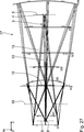
2 in einem Meridionalschnitt eine Ausführung einer abbildenden Optik, die als Projektionsobjektiv in der Projektionsbelichtungsanlage nach 1 einsetzbar ist, wobei ein Abbildungsstrahlengang für Hauptstrahlen und für einen oberen und einen unteren Komastrahl zweier ausgewählter Feldpunkte dargestellt ist; 2 in a meridional section, an embodiment of an imaging optic, which follows as a projection objective in the projection exposure apparatus 1 can be used, wherein an imaging beam path for main beams and for an upper and a lower Komastrahl two selected field points is shown;
3 bis 13 jeweils in einer zu 2 ähnlichen Darstellung weitere Ausführungen einer abbildenden Optik, einsetzbar als Projektionsobjektiv in der Projektionsbelichtungsanlage nach 1; 3 to 13 each in one too 2 Similar representation further embodiments of an imaging optics, used as a projection lens in the projection exposure system according to 1 ;
14 in einer zu 2 ähnlichen Darstellung eine weitere Ausführung einer abbildenden Optik, einsetzbar als Projektionsobjektiv in der Projektionsbelichtungsanlage nach 1, mit einem gekrümmten Feld und divergent vom Objektfeld ausgehenden Hauptstrahlen; 14 in one too 2 a similar embodiment, a further embodiment of an imaging optics, used as a projection lens in the projection exposure system according to 1 , with a curved field and main rays divergent from the object field;
15 eine Ansicht der abbildenden Optik nach 14, gesehen aus Blickrichtung XV in 14; 15 a view of the imaging optics behind 14 , seen from view XV in 14 ;
15A Aufsichten auf Randkonturen optisch genutzter Flächen der Spiegel der abbildenden Optik nach den 14 und 15; 15A Supervision on edge contours of optically used surfaces of the mirror of the imaging optics after the 14 and 15 ;
16 in einer zu 2 ähnlichen Darstellung eine weitere Ausführung einer abbildenden Optik, einsetzbar als Projektionsobjektiv in der Projektionsbelichtungsanlage nach 1; 16 in one too 2 a similar embodiment, a further embodiment of an imaging optics, used as a projection lens in the projection exposure system according to 1 ;
17 eine Ansicht der abbildenden Optik nach 16, gesehen aus Blickrichtung XVII in 16; 17 a view of the imaging optics behind 16 , seen from view XVII in 16 ;
18 in einer zu 2 ähnlichen Darstellung eine weitere Ausführung einer abbildenden Optik, einsetzbar als Projektionsobjektiv in der Projektionsbelichtungsanlage nach 1; 18 in one too 2 a similar embodiment, a further embodiment of an imaging optics, used as a projection lens in the projection exposure system according to 1 ;
19 eine Ansicht der abbildenden Optik nach 18, gesehen aus Blickrichtung XIX in 18; 19 a view of the imaging optics behind 18 , seen from view XIX in 18 ;
20 in einer zu 2 ähnlichen Darstellung eine weitere Ausführung einer abbildenden Optik, einsetzbar als Projektionsobjektiv in der Projektionsbelichtungsanlage nach 1, ausgestaltet als anamorphotische Optik; 20 in one too 2 a similar embodiment, a further embodiment of an imaging optics, used as a projection lens in the projection exposure system according to 1 , designed as anamorphic optics;
21 eine Ansicht der abbildenden Optik nach 20, gesehen aus Blickrichtung XXI in 20; 21 a view of the imaging optics behind 20 , seen from view XXI in 20 ;
21A Aufsichten auf Randkonturen optisch genutzter Flächen der Spiegel der abbildenden Optik nach den 20 und 21; 21A Supervision on edge contours of optically used surfaces of the mirror of the imaging optics after the 20 and 21 ;
22 in einer zu 2 ähnlichen Darstellung eine weitere Ausführung einer abbildenden Optik, einsetzbar als Projektionsobjektiv in der Projektionsbelichtungsanlage nach 1, ausgestaltet als anamorphotische Optik; 22 in one too 2 a similar embodiment, a further embodiment of an imaging optics, used as a projection lens in the projection exposure system according to 1 , designed as anamorphic optics;
23 eine Ansicht der abbildenden Optik nach 22, gesehen aus Blickrichtung XXIII in 22; 23 a view of the imaging optics behind 22 , seen from view XXIII in 22 ;
24 in einer zu 2 ähnlichen Darstellung eine weitere Ausführung einer abbildenden Optik, einsetzbar als Projektionsobjektiv in der Projektionsbelichtungsanlage nach 1, ausgestaltet als anamorphotische Optik; 24 in one too 2 a similar embodiment, a further embodiment of an imaging optics, used as a projection lens in the projection exposure system according to 1 , designed as anamorphic optics;
25 eine Ansicht der abbildenden Optik nach 24, gesehen aus Blickrichtung XXV in 24; 25 a view of the imaging optics behind 24 , seen from view XXV in 24 ;
26 in einer zu 2 ähnlichen Darstellung eine weitere Ausführung einer abbildenden Optik, einsetzbar als Projektionsobjektiv in der Projektionsbelichtungsanlage nach 1, ausgestaltet als anamorphotische Optik ohne Pupillenobskuration; und 26 in one too 2 a similar embodiment, a further embodiment of an imaging optics, used as a projection lens in the projection exposure system according to 1 , designed as anamorphic optics without pupil obscuration; and
27 eine Ansicht der abbildenden Optik nach 26, gesehen aus Blickrichtung XXVII in 26. 27 a view of the imaging optics behind 26 , seen from view XXVII in 26 ,
Eine Projektionsbelichtungsanlage 1 für die Mikrolithographie hat eine Lichtquelle 2 für Beleuchtungslicht bzw. Abbildungslicht 3. Bei der Lichtquelle 2 handelt es sich um eine EUV-Lichtquelle, die Licht in einem Wellenlängenbereich beispielsweise zwischen 5 nm und 30 nm, insbesondere zwischen 5 nm und 15 nm, erzeugt. Bei der Lichtquelle 2 kann es sich insbesondere um eine Lichtquelle mit einer Wellenlänge von 13,5 nm oder um eine Lichtquelle mit einer Wellenlänge von 6,9 nm handeln. Auch andere EUV-Wellenlängen sind möglich. Generell sind sogar beliebige Wellenlängen, zum Beispiel sichtbare Wellenlängen oder auch andere Wellenlängen, die in der Mikrolithographie Verwendung finden können (z. B. DUV, tiefes Ultraviolett) und für die geeigneten Laserlichtquellen und/oder LED-Lichtquellen zur Verfügung stehen (beispielsweise 365 nm, 248 nm, 193 nm, 157 nm, 129 nm, 109 nm), für das in der Projektionsbelichtungsanlage 1 geführte Beleuchtungslicht 3 möglich. Ein Strahlengang des Beleuchtungslichts 3 ist in der 1 äußerst schematisch dargestellt.A projection exposure machine 1 for microlithography has a light source 2 for illumination light or imaging light 3 , At the light source 2 it is an EUV light source, the light in one Wavelength range, for example, between 5 nm and 30 nm, in particular between 5 nm and 15 nm produced. At the light source 2 it may in particular be a light source with a wavelength of 13.5 nm or a light source with a wavelength of 6.9 nm. Other EUV wavelengths are possible. In general, even arbitrary wavelengths, for example visible wavelengths or also other wavelengths, which can be used in microlithography (eg DUV, deep ultraviolet) and are available for the suitable laser light sources and / or LED light sources (for example 365 nm) , 248 nm, 193 nm, 157 nm, 129 nm, 109 nm), for the in the projection exposure apparatus 1 led lighting light 3 possible. A beam path of the illumination light 3 is in the 1 shown very schematically.
Zur Führung des Beleuchtungslichts 3 von der Lichtquelle 2 hin zu einem Objektfeld 4 in einer Objektebene 5 dient eine Beleuchtungsoptik 6. Mit einer Projektionsoptik bzw. abbildenden Optik 7 wird das Objektfeld 4 in ein Bildfeld 8 in einer Bildebene 9 mit einem vorgegebenen Verkleinerungsmaßstab abgebildet. For guiding the illumination light 3 from the light source 2 towards an object field 4 in an object plane 5 serves a lighting optics 6 , With a projection optics or imaging optics 7 becomes the object field 4 in a picture field 8th in an image plane 9 mapped with a given reduction scale.
Zur Erleichterung der Beschreibung der Projektionsbelichtungsanlage 1 sowie der verschiedenen Ausführungen der Projektionsoptik 7 ist in der Zeichnung ein kartesisches xyz-Koordinatensystem angegeben, aus dem sich die jeweilige Lagebeziehung der in den Figuren dargestellten Komponenten ergibt. In der 1 verläuft die x-Richtung senkrecht zur Zeichenebene in diese hinein. Die y-Richtung verläuft nach links und die z-Richtung nach oben.To facilitate the description of the projection exposure apparatus 1 as well as the different versions of the projection optics 7 in the drawing, a Cartesian xyz coordinate system is given, from which the respective positional relationship of the components shown in the figures results. In the 1 the x-direction is perpendicular to the plane of the drawing. The y-direction runs to the left and the z-direction to the top.
Das Objektfeld 4 und das Bildfeld 8 sind rechteckförmig. Alternativ ist es auch möglich, das Objektfeld 4 und Bildfeld 8 gebogen bzw. gekrümmt, also insbesondere teilringförmig auszuführen. Das Objektfeld 4 und das Bildfeld 8 haben ein xy-Aspektverhältnis größer als 1. Das Objektfeld 4 hat also eine längere Objektfelddimension in der x-Richtung und eine kürzere Objektfelddimension in der y-Richtung. Diese Objektfelddimensionen verlaufen längs der Feldkoordinaten x und y. The object field 4 and the picture box 8th are rectangular. Alternatively, it is also possible to use the object field 4 and picture box 8th curved or curved, so in particular perform part-ring. The object field 4 and the picture box 8th have an xy aspect ratio greater than 1. The object field 4 thus has a longer object field dimension in the x direction and a shorter object field dimension in the y direction. These object field dimensions run along the field coordinates x and y.
Für die Projektionsoptik 7 kann eines der in den 2ff. dargestellten Ausführungsbeispiele eingesetzt werden. Die Projektionsoptik 7 nach 2 verkleinert um einen Faktor 8. Auch andere Verkleinerungsmaßstäbe sind möglich, zum Beispiel 4x, 5x oder auch Verkleinerungsmaßstäbe, die größer sind als 8x. Die Bildebene 9 ist bei der Projektionsoptik 7 in den Ausführungen nach den 2 und 5ff. parallel zur Objektebene 5 angeordnet. Abgebildet wird hierbei ein mit dem Objektfeld 4 zusammenfallender Ausschnitt einer Reflexionsmaske 10, die auch als Retikel bezeichnet wird. Das Retikel 10 wird von einem Retikelhalter 10a getragen. Der Retikelhalter 10a wird von einem Retikelverlagerungsantrieb 10b verlagert. For the projection optics 7 can one of the in the 2 ff. Illustrated embodiments are used. The projection optics 7 to 2 reduced by a factor of 8. Also other reduction scales are possible, for example 4x, 5x or even reduction scales, which are larger than 8x. The picture plane 9 is in the projection optics 7 in the comments after the 2 and 5 ff. parallel to the object plane 5 arranged. Here, one is shown with the object field 4 coincident section of a reflection mask 10 , which is also called reticle. The reticle 10 is from a reticle holder 10a carried. The reticle holder 10a is powered by a reticle displacement drive 10b relocated.
Die Abbildung durch die Projektionsoptik 7 erfolgt auf die Oberfläche eines Substrats 11 in Form eines Wafers, der von einem Substrathalter 12 getragen wird. Der Substrathalter 12 wird von einem Wafer- bzw. Substratverlagerungsantrieb 12a verlagert. The picture through the projection optics 7 takes place on the surface of a substrate 11 in the form of a wafer made by a substrate holder 12 will be carried. The substrate holder 12 is from a wafer or substrate displacement drive 12a relocated.
In der 1 ist schematisch zwischen dem Retikel 10 und der Projektionsoptik 7 ein in diese einlaufendes Strahlenbündel 13 des Beleuchtungslichts 3 und zwischen der Projektionsoptik 7 und dem Substrat 11 ein aus der Projektionsoptik 7 auslaufendes Strahlenbündel 14 des Beleuchtungslichts 3 dargestellt. Eine bildfeldseitige numerische Apertur (NA) der Projektionsoptik 7 ist in der 1 nicht maßstäblich wiedergegeben.In the 1 is schematically between the reticle 10 and the projection optics 7 an incoming into this bundle of rays 13 of the illumination light 3 and between the projection optics 7 and the substrate 11 one from the projection optics 7 leaking radiation beam 14 of the illumination light 3 shown. An image field-side numerical aperture (NA) of the projection optics 7 is in the 1 not reproduced to scale.
Die Projektionsbelichtungsanlage 1 ist vom Scannertyp. Sowohl das Retikel 10 als auch das Substrat 11 werden beim Betrieb der Projektionsbelichtungsanlage 1 in der y-Richtung gescannt. Auch ein Steppertyp der Projektionsbelichtungsanlage 1, bei dem zwischen einzelnen Belichtungen des Substrats 11 eine schrittweise Verlagerung des Retikels 10 und des Substrats 11 in der y-Richtung erfolgt, ist möglich. Diese Verlagerungen erfolgen synchronisiert zueinander durch entsprechende Ansteuerung der Verlagerungsantriebe 10b und 12a.The projection exposure machine 1 is the scanner type. Both the reticle 10 as well as the substrate 11 be during operation of the projection exposure system 1 scanned in the y direction. Also a stepper type of the projection exposure system 1 in which between individual exposures of the substrate 11 a gradual shift of the reticle 10 and the substrate 11 in the y-direction is possible. These displacements are synchronized with each other by appropriate control of the displacement drives 10b and 12a ,
2 zeigt das optische Design einer ersten Ausführung der Projektionsoptik 7. Dargestellt ist in der 2 der Strahlengang jeweils dreier Einzelstrahlen 15, die von zwei in der 2 zueinander in der y-Richtung beabstandeten Objektfeldpunkten ausgehen. Dargestellt sind Hauptstrahlen 16, also Einzelstrahlen 15, die durch das Zentrum einer Pupille in einer Pupillenebene der Projektionsoptik 7 verlaufen, sowie jeweils ein oberer und ein unterer Komastrahl dieser beiden Objektfeldpunkte. Ausgehend vom Objektfeld 4 schließen die Hauptstrahlen 16 mit einer Normalen auf die Objektebene 5 einen Winkel CRAO von 5,5 ° ein. 2 shows the optical design of a first embodiment of the projection optics 7 , Shown in the 2 the beam path in each case three individual beams 15 by two in the 2 go out to each other in the y-direction spaced object field points. Shown are main rays 16 , so individual rays 15 passing through the center of a pupil in a pupil plane of the projection optics 7 run, and in each case an upper and a lower coma beam of these two object field points. Starting from the object field 4 close the main beams 16 with a normal to the object plane 5 an angle CRAO of 5.5 °.
Die Objektebene 5 liegt parallel zur Bildebene 9. The object plane 5 lies parallel to the image plane 9 ,
Die Projektionsoptik 7 hat eine bildseitige numerische Apertur von 0,45. The projection optics 7 has a picture-side numerical aperture of 0.45.
Die Projektionsoptik 7 hat einen verkleinernden Abbildungsmaßstab von 8x.The projection optics 7 has a decreasing magnification of 8x.
Die Projektionsoptik 7 nach 2 hat insgesamt acht Spiegel, die in der Reihenfolge des Strahlengangs der Einzelstrahlen 15, ausgehend vom Objektfeld 4, mit M1 bis M8 durchnummeriert sind. Eine abbildende Optik 7 kann auch eine andere Spiegelanzahl haben, beispielsweise vier Spiegel oder sechs Spiegel. The projection optics 7 to 2 has a total of eight mirrors, which are in the order of the beam path of the individual beams 15 , starting from the object field 4 , numbered M1 to M8. An imaging optic 7 may also have a different number of mirrors, for example, four mirrors or six mirrors.
Dargestellt sind in der 2 die berechneten Reflexionsflächen der Spiegel M1 bis M8. Genutzt wird, wie in der Darstellung nach 2 ersichtlich ist, nur ein Teilbereich dieser berechneten Reflexionsflächen. Lediglich dieser tatsächlich genutzte Bereich der Reflexionsflächen ist bei den realen Spiegeln M1 bis M8 tatsächlich vorhanden. Diese Nutz-Reflexionsflächen werden in bekannter Weise von Spiegelkörpern getragen. Shown in the 2 the calculated reflection surfaces of the mirrors M1 to M8. Is used, as shown in the illustration 2 it can be seen, only a portion of these calculated reflection surfaces. Only this actually used area of the reflection surfaces is actually present in the real mirrors M1 to M8. These useful reflection surfaces are supported in known manner by mirror bodies.
Bei der Projektionsoptik 7 nach 2 sind die Spiegel M1, M4, M7 und M8 als Spiegel für normalen Einfall ausgeführt, also als Spiegel, auf die das Abbildungslicht 3 mit einem Einfallswinkel trifft, der kleiner ist als 45 °. Insgesamt hat die Projektionsoptik 7 nach 2 also vier Spiegel M1, M4, M7 und M8 für normalen Einfall. In the projection optics 7 to 2 the mirrors M1, M4, M7 and M8 are designed as mirrors for normal incidence, ie as mirrors, onto which the imaging light is incident 3 with an angle of incidence less than 45 °. Overall, the projection optics 7 to 2 So four mirrors M1, M4, M7 and M8 for normal incidence.
Die Spiegel M2, M3, M5 und M6 sind Spiegel für streifenden Einfall des Beleuchtungslichts 3, also Spiegel, auf die das Beleuchtungslicht 3 mit Einfallswinkeln auftritt, die größer sind als 60 °. Ein typischer Einfallswinkel der Einzelstrahlen 15 des Abbildungslichts 3 auf den Spiegeln M2, M3 sowie M5, M6 für streifenden Einfall liegt im Bereich von 80 °. Insgesamt hat die Projektionsoptik 7 nach 2 genau vier Spiegel M2, M3, M5 und M6 für streifenden Einfall. The mirrors M2, M3, M5 and M6 are mirrors for grazing incidence of the illumination light 3 , ie mirrors, on which the illumination light 3 with angles of incidence greater than 60 °. A typical angle of incidence of individual rays 15 of picture light 3 on mirrors M2, M3 and M5, M6 for grazing incidence is in the range of 80 °. Overall, the projection optics 7 to 2 exactly four mirrors M2, M3, M5 and M6 for grazing incidence.
Die Spiegel M2 und M3 bilden ein direkt im Strahlengang des Abbildungslichts 3 hintereinander angeordnetes Spiegel-Paar. Auch die Spiegel M5 und M6 bilden ein im Strahlengang des Abbildungslichts 3 direkt hintereinander angeordnetes Spiegel-Paar. The mirrors M2 and M3 form directly in the beam path of the imaging light 3 successively arranged mirror pair. Mirrors M5 and M6 also form in the beam path of the imaging light 3 directly behind each other arranged mirror pair.
Die Spiegel-Paare M2, M3 einerseits und M5, M6 andererseits reflektieren das Abbildungslicht 3 so, dass sich die Ausfallswinkel der Einzelstrahlen 15 auf den jeweiligen Spiegeln M2, M3 bzw. M5, M6 dieser beiden Spiegel-Paare addieren. Der jeweils zweite Spiegel M3 und M6 des jeweiligen Spiegel-Paares M2, M3 und M5, M6 verstärkt also eine umlenkende Wirkung, die der jeweils erste Spiegel M2, M5 auf den jeweiligen Einzelstrahl 15 ausübt. Diese Anordnung der Spiegel der Spiegel-Paare M2, M3 bzw. M5, M6 entspricht derjenigen, die in der DE 10 2009 045 096 A1 für eine Beleuchtungsoptik beschrieben ist. The mirror pairs M2, M3 on the one hand and M5, M6 on the other hand reflect the imaging light 3 so that the angles of failure of the individual rays 15 on the respective mirrors M2, M3 and M5, M6 of these two mirror pairs add. The respective second mirror M3 and M6 of the respective mirror pair M2, M3 and M5, M6 thus amplifies a deflecting effect, the respective first mirror M2, M5 on the respective individual beam 15 exercises. This arrangement of the mirrors of the mirror pairs M2, M3 and M5, M6 corresponds to that in the DE 10 2009 045 096 A1 is described for a lighting optics.
Die Spiegel M2, M3, M5 und M6 für streifenden Einfall haben jeweils sehr große absolute Radiuswerte, weichen von einer ebenen Fläche also vergleichsweise gering ab. Diese Spiegel M2, M3, M5 und M6 für streifenden Einfall haben also praktisch keine Brechkraft, also praktisch keine insgesamt bündelformende Wirkung, wie ein konkaver oder konvexer Spiegel, sondern tragen zur spezifischen und insbesondere zur lokalen Abbildungsfehlerkorrektur bei. The grazing incidence mirrors M2, M3, M5 and M6 each have very large absolute radius values, ie deviate comparatively slightly from a flat surface. These grazing incidence mirrors M2, M3, M5 and M6 thus have practically no refractive power, ie virtually no overall bundle-forming effect, such as a concave or convex mirror, but contribute to the specific and especially to the local aberration correction.
Zur Charakterisierung einer umlenkenden Wirkung der Spiegel der Projektionsoptik 7 wird nachfolgend anhand der jeweils dargestellten Meridionalschnitte eine Umlenkrichtung definiert. Gesehen in der jeweils einfallenden Strahlrichtung im Meridionalschnitt beispielsweise nach 2 wird eine umlenkende Wirkung des jeweiligen Spiegels im Uhrzeigersinn, also eine Ablenkung nach rechts, mit dem Kürzel „R“ gekennzeichnet. Der Spiegel M1 der Projektionsoptik 7 hat beispielsweise eine solche umlenkende Wirkung „R“. Eine umlenkende Wirkung eines Spiegels entgegen dem Uhrzeigersinn, also nach links, gesehen aus der jeweils auf diesen Spiegel einfallenden Strahlrichtung, wird mit dem Kürzel „L“ gekennzeichnet. Die Spiegel M2 und M3 der Projektionsoptik 7 sind Beispiele für die umlenkende Wirkung „L“. Eine schwach oder überhaupt nicht umlenkende Wirkung eines Spiegels mit einem Faltwinkel f, für den gilt: –1° < f < 1°, wird mit dem Kürzel „0“ gekennzeichnet. Der Spiegel M7 der Projektionsoptik 7 ist ein Beispiel für die umlenkende Wirkung „0“. Ingesamt hat die Projektionsoptik 7 für die Spiegel M1 bis M8 folgende Abfolge umlenkender Wirkungen: RLLLRR0L. To characterize a deflecting effect of the mirrors of the projection optics 7 Subsequently, a deflection direction is defined on the basis of the respectively illustrated meridional sections. Seen in the respective incident beam direction in the meridional section, for example, after 2 is a deflecting effect of each mirror clockwise, so a deflection to the right, marked with the abbreviation "R". The mirror M1 of the projection optics 7 has, for example, such a deflecting effect "R". A deflecting effect of a mirror in the counterclockwise direction, that is to the left, as seen from the respective beam direction incident on this mirror, is identified by the abbreviation "L". The mirrors M2 and M3 of the projection optics 7 are examples of the redirecting effect "L". A weakly or not at all deflecting effect of a mirror with a folding angle f, for which applies: -1 ° <f <1 °, is marked with the abbreviation "0". M7 mirror of projection optics 7 is an example of the redirecting effect "0". Overall, the projection optics 7 for the mirrors M1 to M8 the following sequence of redirecting effects: RLLLRR0L.
Grundsätzlich können alle beschriebenen Ausführungsbeispiele der Projektionsoptiken um eine Ebene, die parallel zur xz-Ebene verläuft, gespiegelt werden, ohne dass sich hierbei grundlegende Abbildungseigenschaften ändern. Allerdings ändert sich dann natürlich die Abfolge der umlenkenden Wirkungen, die beispielsweise bei einer Projektionsoptik, die durch entsprechende Spiegelung aus der Projektionsoptik 7 hervorgeht, folgende Reihenfolge hat: LRRRLL0R.In principle, all described embodiments of the projection optics can be mirrored around a plane that runs parallel to the xz plane, without changing basic imaging properties. However, then, of course, the sequence of the deflecting effects changes, for example, in the case of projection optics, which are mirrored out of the projection optics 7 shows the following order: LRRRLL0R.
Eine Wahl der Umlenkwirkung, also eine Wahl einer Richtung des jeweils einfallenden Strahls beispielsweise auf den Spiegel M4 und eine Wahl einer Ablenkrichtung der Spiegelpaare M2, M3 sowie M5, M6 wird jeweils so gewählt, dass ein für die Projektionsoptik 7 zur Verfügung stehender Bauraum effizient genutzt wird. A choice of the deflecting effect, ie a choice of a direction of the respective incident beam, for example, on the mirror M4 and a choice of a deflection of the mirror pairs M2, M3 and M5, M6 is selected in each case so that one for the projection optics 7 available space is used efficiently.
Die Spiegel M1 bis M8 tragen eine die Reflektivität der Spiegel M1 bis M8 für das Abbildungslicht 3 optimierende Beschichtung. Hierbei kann es sich um eine Ruthenium-Beschichtung, um eine Molybdän-Beschichtung oder um eine Molybdän-Beschichtung mit einer obersten Schicht aus Ruthenium handeln. Bei den Spiegeln M2, M3, M5 und M6 für streifenden Einfall kann eine Beschichtung mit beispielsweise einer Lage aus Molybdän oder Ruthenium zum Einsatz kommen. Diese hoch reflektierenden Schichten insbesondere der Spiegel M1, M4, M7 und M8 für normalen Einfall können als Mehrlagen-Schichten ausgeführt sein, wobei aufeinanderfolgende Schichten aus unterschiedlichen Materialien gefertigt sein können. Auch alternierende Materialschichten können zum Einsatz kommen. Eine typische Mehrlagenschicht kann fünfzig Bilagen aus jeweils einer Schicht Molybdän und einer Schicht Silizium aufweisen. The mirrors M1 to M8 carry the reflectivity of the mirrors M1 to M8 for the imaging light 3 optimizing coating. This may be a ruthenium coating, a molybdenum coating or a molybdenum coating having a topmost layer of ruthenium. For grazing incidence mirrors M2, M3, M5 and M6, a coating of, for example, a layer of molybdenum or ruthenium may be used. These highly reflective layers, in particular the mirrors M1, M4, M7 and M8 for normal incidence, can be embodied as multilayer layers, wherein successive layers can be made of different materials. Alternate layers of material can also be used. A typical multi-layer layer may comprise fifty bilayers each of one layer of molybdenum and one layer of silicon.
Zur Berechnung einer Gesamt-Reflektivität der Projektionsoptik 7 wird eine Systemtransmission wie folgt berechnet: Eine Spiegel-Reflektivität wird in Abhängigkeit vom Einfallswinkel eines Führungsstrahls, also eines Hauptstrahls eines zentralen Objektfeldpunktes, an jeder Spiegelfläche bestimmt und multiplikativ zur Systemtransmission zusammengefasst. To calculate a total reflectivity of the projection optics 7 a system transmission is calculated as follows: A mirror reflectivity is determined as a function of the angle of incidence of a guide beam, ie a main beam of a central object field point, on each mirror surface and combined in a multiplicative manner to the system transmission.
Die Reflektivität RM an einem Spiegel in Prozent ergibt sich dabei zu: RM = c0x4 + c1x3 + c2x2 + c3x + c4 x bezeichnet hierbei den jeweiligen Einfallswinkel in Grad. Die Koeffizienten ci ergeben sich zu: ci = 1/2(ciS-fit + ciP-fit) als Mittelwerte der jeweiligen Koeffizienten für S-Polarisation einerseits und die P-Polarisation andererseits. The reflectivity R M at a mirror in percent results in: R M = c0x 4 + C1x 3 + c2x + 2 + c4 c3x x denotes the respective angle of incidence in degrees. The coefficients ci result in: ci = 1/2 (ci S-fit + ci P-fit ) as averages of the respective coefficients for S-polarization on the one hand and the P-polarization on the other.
Für einen Einfallswinkelbereich von 60° < x < 88° ergeben sich für eine Rutheniumschicht, die also unter grazing incidence-Winkeln beaufschlagt wird, folgende Koeffizienten: c0 c1 c2 c3 c4
S-Fit 0 1,59347283 × 10⁻³ –4,06503596 × 10⁻¹ 3,56423129 × 101 –9,76664971 × 10²
P-Fit 0 1,88179657 × 10⁻³ –4,79626971 × 10⁻¹ 4,20429269 × 101 –1,17059654 × 10³
For an incident angle range of 60 ° <x <88 °, the following coefficients result for a ruthenium layer, which is thus subjected to grazing incidence angles: c0 c1 c2 c3 c4
S-Fit 0 1.59347283 × 10 -3 -4.06503596 × 10 -1 3.56423129 × 10 1 -9,76664971 × 10 2
P-Fit 0 1.88179657 × 10 -3 -4,796,269,771 × 10 -1 4,20429269 × 10 1 -1,17059654 × 10 3
Für NI-Spiegel, also im Bereich der senkrechten Inzidenz, erbeben sich für einen Molybdän/Silizium-Mehrlagenstapel: c0 c1 c2 c3 c4
S-Fit 2,89135870 × 10⁻⁶ –3,90173053 × 10⁻⁴ 1,04448085 × 10⁻² –2,65742974 × 10⁻² 6,66009436 × 101
P-Fit 2,05886567 × 10⁻⁵ 5,79240629 × 10⁻⁴ –3,37849733 × 10⁻² 3,92206533 × 10⁻² 6,65307365 × 101
For NI levels, ie in the area of vertical incidence, a molybdenum / silicon multilayer stack is shaken: c0 c1 c2 c3 c4
S-Fit 2,89135870 × 10 -6 -3.90173053 × 10 -4 1.04448085 × 10 -2 -2,657,42974 × 10 -2 6,66009436 × 10 1
P-Fit 2.05886567 × 10 -5 5,792,40629 × 10 -4 -3,37849733 × 10 -2 3.92206533 × 10 -2 6,65307365 × 10 1
Weitere Informationen zur Reflexion an einem GI-Spiegel (Spiegel für streifenden Einfall) finden sich in der WO 2012/126867 A . Weitere Informationen zur Reflektivität von NI-Spiegeln (Normal Incidence Spiegeln) finden sich in der DE 101 55 711 A .Further information on reflection at a GI mirror (grazing incidence mirror) can be found in the WO 2012/126867 A , Further information on the reflectivity of NI mirrors (normal incidence mirrors) can be found in the DE 101 55 711 A ,
Eine Gesamt-Reflektivität bzw. Systemtransmission der Projektionsoptik 7, die sich als Produkt der Reflektivitäten aller Spiegel M1 bis M8 der Projektionsoptik 7 ergibt, beträgt R = 10,43 %.A total reflectivity or system transmission of the projection optics 7 , which are a product of the reflectivities of all mirrors M1 to M8 of the projection optics 7 gives R = 10.43%.
Der Spiegel M8, also der im Abbildungsstrahlengang letzte Spiegel vor dem Bildfeld 8, hat eine Durchtrittsöffnung 17 zum Durchtritt des Abbildungslichts 3, das vom drittletzten Spiegel M6 hin zum vorletzten Spiegel M7 reflektiert wird. Der Spiegel M8 wird um die Durchtrittsöffnung 17 herum reflektiv genutzt. Alle anderen Spiegel M1 bis M7 haben keine Durchtrittsöffnung und werden in einem lückenlos zusammenhängenden Bereich reflektiv genutzt. The mirror M8, so the last in the imaging beam path mirror in front of the image field 8th , has a passage opening 17 to the passage of the imaging light 3 which is reflected from the third last mirror M6 toward the penultimate mirror M7. The mirror M8 is around the passage opening 17 around used reflectively. All other mirrors M1 to M7 have no passage opening and are used in a coherently coherent area reflective.
Die Spiegel M1 bis M8 sind als nicht durch eine rotationssymmetrische Funktion beschreibbare Freiformflächen ausgeführt. Es sind auch andere Ausführungen der Projektionsoptik 7 möglich, bei denen mindestens einer der Spiegel M1 bis M8 als rotationssymmetrische Asphäre ausgeführt ist. Auch alle Spiegel M1 bis M8 können als derartige Asphären ausgeführt sein. The mirrors M1 to M8 are designed as freeform surfaces which can not be described by a rotationally symmetrical function. There are also other versions of the projection optics 7 possible in which at least one of the mirrors M1 to M8 is designed as a rotationally symmetric asphere. All mirrors M1 to M8 can also be designed as such aspheres.
Eine Freiformfläche kann durch folgende Freiformflächengleichung (Gleichung 1) beschrieben werden: A free-form surface can be described by the following free-form surface equation (Equation 1):
Für die Parameter dieser Gleichung (1) gilt:
Z ist die Pfeilhöhe der Freiformfläche am Punkt x, y, wobei x2 + y2 = r2. r ist hierbei der Abstand zur Referenzachse der Freiformflächengleichung (x = 0; y = 0). For the parameters of this equation (1):
Z is the arrow height of the freeform surface at point x, y, where x 2 + y 2 = r 2 . r is the distance to the reference axis of the freeform surface equation (x = 0, y = 0).
In der Freiformflächengleichung (1) bezeichnen C1, C2, C3 ... die Koeffizienten der Freiformflächen-Reihenentwicklung in den Potenzen von x und y.In the free-form surface equation (1), C 1 , C 2 , C 3 ... designate the coefficients of the free-form surface series expansion in the powers of x and y.
Im Falle einer konischen Grundfläche ist cx, cy eine Konstante, die der Scheitelpunktkrümmung einer entsprechenden Asphäre entspricht. Es gilt also cx = 1/Rx und cy = 1/Ry. kx und ky entsprechen jeweils einer konischen Konstante einer entsprechenden Asphäre. Die Gleichung (1) beschreibt also eine bikonische Freiformfläche.In the case of a conical base, c x , c y is a constant that corresponds to the vertex curvature of a corresponding asphere. So c x = 1 / R x and c y = 1 / R y . k x and k y each correspond to a conical constant of a corresponding asphere. The equation (1) thus describes a biconical freeform surface.
Eine alternativ mögliche Freiformfläche kann aus einer rotationssymmetrischen Referenzfläche erzeugt werden. Derartige Freiformflächen für Reflexionsflächen der Spiegel von Projektionsoptiken von Projektionsbelichtungsanlagen für die Mikrolithographie sind bekannt aus der US 2007-0058269 A1 . An alternatively possible free-form surface can be generated from a rotationally symmetrical reference surface. Such free-form surfaces for reflecting surfaces of the mirrors of projection optics of projection exposure apparatuses for microlithography are known from US Pat US 2007-0058269 A1 ,
Alternativ können Freiformflächen auch mit Hilfe zweidimensionaler Spline-Oberflächen beschrieben werden. Beispiele hierfür sind Bezier-Kurven oder nicht-uniforme rationale Basis-Splines (non-uniform rational basis splines, NURBS). Zweidimensionale Spline-Oberflächen können beispielsweise durch ein Netz von Punkten in einer xy-Ebene und zugehörige z-Werte oder durch diese Punkte und ihnen zugehörige Steigungen beschrieben werden. Abhängig vom jeweiligen Typ der Spline-Oberfläche wird die vollständige Oberfläche durch Interpolation zwischen den Netzpunkten unter Verwendung z. B. von Polynomen oder Funktionen, die bestimmte Eigenschaften hinsichtlich ihrer Kontinuität und Differenzierbarkeit haben, gewonnen. Beispiele hierfür sind analytische Funktionen. Alternatively, freeform surfaces can also be described using two-dimensional spline surfaces. Examples include Bezier curves or non-uniform rational base splines (NURBS). For example, two-dimensional spline surfaces may be described by a network of points in an xy plane and associated z-values or by these points and their associated slopes. Depending on the particular type of spline surface, the complete surface is obtained by interpolating between the mesh points using e.g. As polynomials or functions that have certain properties in terms of their continuity and differentiability won. Examples of this are analytical functions.
Die optischen Designdaten der Reflexionsflächen der Spiegel M1 bis M8 der Projektionsoptik 7 können den nachfolgenden Tabellen entnommen werden. Diese optischen Designdaten gehen jeweils von der Bildebene 9 aus, beschreiben die jeweilige Projektionsoptik also in umgekehrter Laufrichtung des Abbildungslichts 3 zwischen der Bildebene 9 und der Objektebene 5. The optical design data of the reflection surfaces of the mirrors M1 to M8 of the projection optics 7 can be found in the following tables. Each of these optical design data goes from the image plane 9 from, describe the respective projection optics so in the reverse direction of the imaging light 3 between the picture plane 9 and the object plane 5 ,
Die erste dieser Tabellen gibt einen Überblick über die Designdaten der Projektionsoptik 7 und fasst zusammen die numerische Apertur NA, die gerechnete Designwellenlänge für das Abbildungslicht, die Größen des Bildfeldes in x- und y-Richtung, eine Bildfeldkrümmung sowie einen Blendenort. Diese Krümmung ist definiert als der inverse Krümmungsradius des Feldes. The first of these tables gives an overview of the design data of the projection optics 7 and together summarizes the numerical aperture NA, the calculated design wavelength for the imaging light, the magnitudes of the image field in the x and y directions, a field curvature, and a diaphragm location. This curvature is defined as the inverse radius of curvature of the field.
Die zweite dieser Tabellen gibt zu den optischen Oberflächen der optischen Komponenten Scheitelpunktsradien (Radius_x = Rx, Radius_y = Ry) und Brechkraftwerte (Power_x, Power_y) an. Negative Radienwerte bedeuten zum einfallenden Beleuchtungslicht 3 hin konkave Kurven im Schnitt der jeweiligen Oberfläche mit der betrachteten Ebene (xz, yz), die von einer Flächennormalen im Scheitelpunkt mit der jeweiligen Krümmungsrichtung (x, y) aufgespannt wird. Die beiden Radien Radius_x, Radiux_y können explizit verschiedene Vorzeichen haben. The second of these tables are the optical surfaces of the optical components vertex radii at (Radius_x = R x, R y = Radius_y) and power values (Power_x, Power_y). Negative radii mean the incident illuminating light 3 concave curves in the section of the respective surface with the considered plane (xz, yz), which is spanned by a surface normal at the apex with the respective direction of curvature (x, y). The two radii Radius_x, Radiux_y can explicitly have different signs.
Die Scheitelpunkte an jeder optischen Fläche sind definiert als Auftreffpunkte eines Führungsstrahls, der von einer Objektfeldmitte entlang einer Symmetrieebene x = 0, also der Zeichenebene der 2 (Meridionalebene) hin zum Bildfeld 8 geht. The vertices on each optical surface are defined as points of impingement of a guide beam, which originate from an object field center along a plane of symmetry x = 0, that is to say the plane of the drawing 2 (Meridional plane) towards the image field 8th goes.
Die Brechkräfte Power_x (Px), Power_y (Py) an den Scheitelpunkten sind definiert als: The powers Power_x (P x ), Power_y (P y ) at the vertices are defined as:
AOI bezeichnet hierbei einen Einfallswinkel des Führungsstrahls zur Oberflächennormalen. AOI here denotes an angle of incidence of the guide beam to the surface normal.
Die dritte Tabelle gibt für die Spiegel M1 bis M8 in mm die konischen Konstanten kx und ky, den Scheitelpunktradius Rx (= Radius_x) und die Freifomflächen-Koeffizienten Cn an. Koeffizienten Cn, die nicht tabelliert sind, haben jeweils den Wert 0. The third table gives for the mirrors M1 to M8 in mm the conical constants k x and k y , the vertex radius R x (= radius_x) and the free-face area coefficients C n . Coefficients C n , which are not tabulated, each have the value 0.
In der vierten Tabelle ist noch der Betrag angegeben, längs dem der jeweilige Spiegel, ausgehend von einer Bezugsfläche in der y-Richtung dezentriert (DCY), in der z-Richtung verschoben (DCZ) und verkippt (TLA, TLC) wurde. Dies entspricht einer Parallelverschiebung und einer Verkippung beim Freiformflächen-Designverfahren. Verschoben wird dabei in y- und in z-Richtung in mm und verkippt um die x-Achse und um die z-Achse. Der Verdrehwinkel ist dabei in Grad angegeben. Es wird zunächst dezentriert, dann verkippt. Die Bezugsfläche bei der Dezentrierung ist jeweils die erste Fläche der angegebenen optischen Designdaten. Auch für das Objektfeld 4 ist eine Dezentrierung in y- und in z-Richtung angegeben. Neben den den einzelnen Spiegeln zugeordneten Flächen sind in der vierten Tabelle auch die Bildebene als erste Fläche, die Objektebene als letzte Fläche sowie ggf. eine Blendenfläche (mit der Bezeichnung „Blende“) tabelliert. The fourth table also indicates the amount along which the respective mirror decentred (DCY) from a reference surface in the y direction, was shifted in the z direction (DCZ) and tilted (TLA, TLC). This corresponds to a parallel shift and a tilt in the freeform surface design process. It is shifted in y- and z-direction in mm and tilted around the x-axis and around the z-axis. The twist angle is given in degrees. It is decentered first, then tilted. The reference surface at decentering is the first surface of the specified optical design data. Also for the object field 4 is a decentering in the y and z direction indicated. In addition to the surfaces assigned to the individual mirrors, the fourth table also includes the image plane as the first surface, the object plane as the last surface and, if appropriate, an aperture surface (designated as "aperture").
Die fünfte Tabelle gibt noch die Transmissionsdaten der Spiegel M8 bis M1 an, nämlich deren Reflektivität für den Einfallswinkel eines zentral auf den jeweiligen Spiegel treffenden Beleuchtungslichtstrahls. Die Gesamttransmission wird als Anteilsfaktor angegeben, der von einer einfallenden Intensität nach Reflexion an allen Spiegeln der Projektionsoptik verbleibt.The fifth table also indicates the transmission data of the mirrors M8 to M1, namely their reflectivity for the angle of incidence of an illuminating light beam striking centrally on the respective mirror. The total transmission is given as a proportion factor remaining from an incident intensity after reflection at all mirrors of the projection optics.
Die sechste Tabelle gibt eine Berandung der Blende (Fläche M8) als Polygonzug in lokalen Koordinaten xyz an. Diese Blende ist am Ort des Spiegels M8 angeordnet. Die Blende wird noch wie oben beschrieben dezentriert und verkippt. Tabelle 1 zu Fig. 2 Tabelle 2 zu Fig. 2 Tabelle 3a zu Fig. 2 Tabelle 3b zu Fig. 2 Tabelle 3c zu Fig. 2 Tabelle 4a zu Fig. 2 Tabelle 4b zu Fig. 2 Tabelle 5 zu Fig. 2 Tabelle 6 zu Fig. 2 The sixth table indicates a boundary of the diaphragm (area M8) as a polygon in local coordinates xyz. This aperture is located at the location of the mirror M8. The aperture is still decentered and tilted as described above. Table 1 to Fig. 2 Table 2 to Fig. 2 Table 3a to Fig. 2 Table 3b to Fig. 2 Table 3c to Fig. 2 Table 4a to FIG. 2 Table 4b to Fig. 2 Table 5 to Fig. 2 Table 6 to FIG. 2
Eine Gesamt-Reflektivität der Projektionsoptik 7 beträgt 10,43 %.A total reflectivity of the projection optics 7 is 10.43%.
Die Spiegel M1 bis M7 sind Freiformflächen, bei denen die Freiformflächen-Entwicklung bis maximal zur zehnten Potenz in x und y geht. Beim Spiegel M8 geht diese Entwicklung bis zur zwölften Potenz in x und y. The mirrors M1 to M7 are free-form surfaces in which the free-form surface development is up to a maximum of the tenth power in x and y. In the M8 mirror, this development goes up to the twelfth power in x and y.
Die Rotationssymmetrieachsen der asphärischen Spiegel sind in der Regel gegenüber einer Normalen auf die Bildebene 9 verkippt, wie die tabellierten Verkippungswerte deutlich machen. The rotational symmetry axes of the aspherical mirrors are usually opposite to a normal to the image plane 9 tilted, as the tabulated tilt values make clear.
Die Spiegel M1, M2, M4, M5 und M8 haben negative Radiuswerte, sind also grundsätzlich Konkavspiegel. Die Spiegel M3, M6 und M7 haben positive Radiuswerte, sind grundsätzlich also Konvexspiegel. Die Spiegel M2, M3, M5 und M6 haben sehr große absolute Radien, stellen also nur geringe Abweichungen von ebenen Reflexionsflächen dar. The mirrors M1, M2, M4, M5 and M8 have negative radius values, ie are basically concave mirrors. Mirrors M3, M6 and M7 have positive radii, which are basically convex mirrors. The mirrors M2, M3, M5 and M6 have very large absolute radii, so represent only small deviations from flat reflecting surfaces.
Das Bildfeld 8 hat eine x-Erstreckung von zweimal 6,5 mm und eine y-Erstreckung von 1 mm. Die Projektionsoptik 7 ist optimiert für eine Betriebswellenlänge des Beleuchtungslichts 3 von 13,5 nm. The image field 8th has an x-extension of twice 6.5 mm and a y-extension of 1 mm. The projection optics 7 is optimized for an operating wavelength of the illumination light 3 of 13.5 nm.
Eine erste Pupillenebene 18 ist im Strahlengang des Abbildungslichts 3 zwischen den Spiegeln M2 und M3 angeordnet. Anders als schematisch in der 2 dargestellt, ist die erste Pupillenebene 18 relativ zum Hauptstrahl eines zentralen Feldpunktes verkippt, schließt mit diesem Hauptstrahl also einen Winkel ≠ 90° ein. Zwischen den Spiegeln M2 und M3 ist im Bereich der Pupillenebene 18 das gesamte Bündel des Abbildungslichts 3 von allen Seiten her zugänglich. Im Bereich der Pupillenebene 18 kann daher eine Aperturblende angeordnet sein. Diese Blende wird nachfolgend auch mit der Bezugsziffer 18 bezeichnet. Alternativ oder zusätzlich kann, wie vorstehend im Zusammenhang mit der Tabelle 6 zu 2 erläutert, die Blende auch am Spiegel M8 angeordnet sein.A first pupil level 18 is in the beam path of the imaging light 3 arranged between the mirrors M2 and M3. Other than schematic in the 2 is the first pupil plane 18 tilted relative to the main beam of a central field point, thus encloses an angle ≠ 90 ° with this main beam. Between the mirrors M2 and M3 is in the area of the pupil plane 18 the entire bundle of imaging light 3 accessible from all sides. At the pupil level 18 Therefore, an aperture diaphragm can be arranged. This panel will be described below with the reference number 18 designated. Alternatively or additionally, as in the context of Table 6 above 2 explained, the aperture may also be arranged on the mirror M8.
Eine Berandung einer Blendenfläche der Blende (vgl. auch die Tabelle 6 zur 2) ergibt sich durch Durchstoßpunkte an der Blendenfläche aller Strahlen des Beleuchtungslichts 3, die bildseitig am Feldmittelpunkt mit einer vollen bildseitigen telezentrischen Apertur in Richtung der Blendenfläche propagieren. Bei der Ausführung der Blende als Aperturblende handelt es sich bei der Berandung um eine innere Berandung. A boundary of a diaphragm surface of the diaphragm (see also Table 6 to 2 ) results from puncture points on the diaphragm surface of all rays of the illumination light 3 , which propagate on the image side at the field center with a full image-side telecentric aperture in the direction of the diaphragm surface. When the aperture is designed as an aperture diaphragm, the boundary is an inner boundary.
Die Blende 18 kann in einer Ebene liegen oder auch dreidimensional ausgeführt sein. Die Ausdehnung der Blende 18 kann in Scanrichtung (y) kleiner sein als in cross-Scanrichtung (x).The aperture 18 can be in one plane or three-dimensional. The extension of the aperture 18 can be smaller in the scan direction (y) than in the cross scan direction (x).
Im Abbildungsstrahlengang zwischen den Spiegeln M3 und M4 ist ein Zwischenbild 19 der Projektionsoptik 7 angeordnet. In the imaging beam path between the mirrors M3 and M4 is an intermediate image 19 the projection optics 7 arranged.
Eine weitere Pupillenebene der Projektionsoptik 7 ist im Bereich der Reflexion des Abbildungslichts 3 an den Spiegeln M7 bzw. M8 angeordnet. Aperturblenden im Bereich der Spiegel M7 bzw. M8 können für die x-Dimension einerseits und für die y-Dimension andererseits auf zwei Positionen im Abbildungsstrahlengang verteilt angeordnet sein, zum Beispiel eine Aperturblende zur Begrenzung hauptsächlich längs der y-Dimension auf dem Spiegel M8 und eine Aperturblende zur Begrenzung hauptsächlich längs der x-Dimension auf dem Spiegel M7.Another pupil plane of the projection optics 7 is in the range of the reflection of the imaging light 3 arranged on the mirrors M7 and M8. Aperture apertures in the area of the mirrors M7 and M8 can, for the x-dimension on the one hand and for the y-dimension, on the other hand be distributed in two positions in the imaging beam path, for example an aperture stop for limiting mainly along the y-dimension on the mirror M8 and one Aperture diaphragm for limiting mainly along the x-dimension on the mirror M7.
Eine Baulänge der Projektionsoptik 7 in der z-Richtung, also ein Abstand zwischen der Objektebene 5 und der Bildebene 9, beträgt etwa 2000 mm. Der Spiegel M8 hat einen Durchmesser, der im Bereich von 650 mm liegt. Ein y-Abstand dOIS zwischen einem zentralen Objektfeldpunkt und einem zentralen Bildfeldpunkt beträgt 1870 mm.An overall length of the projection optics 7 in the z-direction, ie a distance between the object plane 5 and the picture plane 9 , is about 2000 mm. The mirror M8 has a diameter that is in the range of 650 mm. A y-distance d OIS between a central object field point and a central image field point is 1870 mm.
Die Projektionsoptik 7 hat einen gescannten RMS-Wert des Wellenfrontfehlers, der kleiner ist als 5 bis 10 mλ. Die Verzeichnung der Projektionsoptik 7 ist kleiner als 0,12 nm. Ein Telezentriewert der Projektionsoptik 7, gemessen in der x-Richtung über das Bildfeld 8, ist kleiner als 6 mrad. Ein Telezentriewert der Projektionsoptik 7, gemessen in der y-Richtung über das Bildfeld 8, ist kleiner als 0,4 mrad. The projection optics 7 has a scanned RMS value of the wavefront error that is less than 5 to 10 mλ. The distortion of the projection optics 7 is less than 0.12 nm. A telecentricity of the projection optics 7 , measured in the x-direction across the image field 8th , is smaller than 6 mrad. A telecentricity of the projection optics 7 , measured in the y direction across the image field 8th , is less than 0.4 mrad.
Die Projektionsoptik 7 ist bildseitig näherungsweise telezentrisch. Ein Arbeitsabstand zwischen dem Bildfeld nächsten Spiegel M7 und dem Bildfeld 8 beträgt 78 mm. The projection optics 7 is approximately telecentric on the image side. A working distance between the image field next mirror M7 and the image field 8th is 78 mm.
Weniger als 15 % der numerischen Apertur sind aufgrund der Durchtrittsöffnung 17 obskuriert. Die Konstruktion der Obskurationsberandung erfolgt analog der vorstehend im Zusammenhang mit der Blende 18 erläuterten Konstruktion der Blendenberandung. Bei der Ausführung als Obskurationsblende handelt es sich bei der Berandung um eine äußere Berandung der Blende. In einer Systempupille der Projektionsoptik 7 ist eine aufgrund der Obskuration nicht beleuchtbare Fläche kleiner als 0,152 der Fläche der gesamten Systempupille. Die nicht beleuchtete Fläche innerhalb der Systempupille kann in der x-Richtung eine andere Ausdehnung haben als in der y-Richtung. Die nicht beleuchtete Fläche in der Systempupille kann rund, elliptisch, quadratisch oder rechteckig sein. Diese nicht beleuchtbare Fläche in der Systempupille kann zudem in Bezug auf ein Zentrum der Systempupille in der x-Richtung und/oder in der y-Richtung dezentriert sein.Less than 15% of the numerical aperture is due to the passage opening 17 obscured. The construction of the obscurant boundary is analogous to that described above in connection with the diaphragm 18 explained construction of the diaphragm boundary. When executed as Obskurationsbrende it is at the boundary to an outer boundary of the aperture. In a system pupil of the projection optics 7 For example, a surface not illuminable due to obscuration is less than 0.15 2 of the area of the entire system pupil. The unilluminated area within the system pupil may have a different extent in the x direction have as in the y-direction. The unilluminated area in the system pupil may be round, elliptical, square or rectangular. This non-illuminable area in the system pupil may also be decentered with respect to a center of the system pupil in the x-direction and / or in the y-direction.
Anhand der 3 wird nachfolgend eine weitere Ausführung einer Projektionsoptik 20 erläutert, die anstelle der Projektionsoptik 7 bei der Projektionsbelichtungsanlage 1 nach 1 zum Einsatz kommen kann. Komponenten und Funktionen, die vorstehend im Zusammenhang mit den 1 und 2 bereits erläutert wurden, tragen gegebenenfalls die gleichen Bezugsziffern und werden nicht nochmals im Einzelnen diskutiert. Based on 3 Below is another embodiment of a projection optics 20 explains that instead of the projection optics 7 at the projection exposure machine 1 to 1 can be used. Components and functions discussed above in connection with the 1 and 2 have already been explained, if applicable, have the same reference numbers and will not be discussed again in detail.
Die Spiegel M1 bis M6 sind wiederum als Freiformflächen-Spiegel ausgeführt, für die die vorstehend angegebene Freiformflächengleichung (1) gilt. Die optischen Designdaten der Projektionsoptik 20 können den nachfolgenden Tabellen entnommen werden, die in ihrem Aufbau den Tabellen zur Projektionsoptik 7 nach 2 entsprechen. Tabelle 1 zur Fig. 3 Tabelle 2 zur Fig. 3 Tabelle 3a zur Fig. 3 Tabelle 3b zur Fig. 3 Tabelle 4a zur Fig. 3 Tabelle 4b zur Fig. 3 Tabelle 5 zur Fig. 3 Tabelle 6 zur Fig. 3 The mirrors M1 to M6 are again embodied as free-form surface mirrors, for which the free-form surface equation (1) specified above applies. The optical design data of the projection optics 20 can be taken from the following tables, which in their structure the tables for projection optics 7 to 2 correspond. Table 1 to FIG. 3 Table 2 to FIG. 3 Table 3a to Fig. 3 Table 3b to FIG. 3 Table 4a to FIG. 3 Table 4b to FIG. 3 Table 5 to FIG. 3 Table 6 to FIG. 3
Eine Gesamt-Reflektivität der Projektionsoptik 20 beträgt 12,99 %.A total reflectivity of the projection optics 20 is 12.99%.
Die Projektionsoptik 20 hat eine bildseitige numerische Apertur von 0,45. Das Bildfeld 8 hat eine x-Erstreckung von zweimal 6,5 mm und eine y-Erstreckung von 1 mm. Die Projektionsoptik 20 ist optimiert für eine Betriebswellenlänge des Beleuchtungslichts 3 von 13,5 nm.The projection optics 20 has a picture-side numerical aperture of 0.45. The image field 8th has an x-extension of twice 6.5 mm and a y-extension of 1 mm. The projection optics 20 is optimized for an operating wavelength of the illumination light 3 of 13.5 nm.
Die Projektionsoptik 20 hat einen verkleinernden Abbildungsmaßstab von 8x (β = 8).The projection optics 20 has a decreasing magnification of 8x (β = 8).
Die Projektionsoptik 20 hat genau sechs Spiegel M1 bis M6. Die Spiegel M1 und M2 sind wiederum als Spiegel für streifenden Einfall ausgeführt und als Spiegel-Paar im Abbildungsstrahlengang direkt hintereinander angeordnet. Die Projektionsoptik 20 hat genau zwei Spiegel für streifenden Einfall, nämlich die Spiegel M1 und M2. Die Spiegel M3 bis M6 sind als Spiegel für normalen Einfall ausgeführt.The projection optics 20 has exactly six mirrors M1 to M6. The mirrors M1 and M2 are in turn designed as a mirror for grazing incidence and arranged as a pair of mirrors in the imaging beam path directly behind one another. The projection optics 20 has exactly two mirrors for grazing incidence, namely the mirrors M1 and M2. The mirrors M3 to M6 are designed as mirrors for normal incidence.
Die Projektionsoptik 20 hat eine Gesamt-Reflektivität, die größer ist als 11,97 %.The projection optics 20 has a total reflectivity that is greater than 11.97%.
Die Objektebene 5 ist gegenüber der Bildebene 9 absolut um einen Winkel von etwa 39 ° um die x-Achse verkippt. Entsprechend ist als Wert TLA für das Objektfeld in der letzten obigen Tabelle (Tabelle 3b zu 3) ein Wert von etwa 219 ° angegeben.The object plane 5 is opposite the picture plane 9 absolutely tilted by an angle of about 39 ° about the x-axis. Accordingly, the value TLA for the object field in the last table above (Table 3b) 3 ) a value of about 219 ° indicated.
Ein z-Abstand zwischen dem Objektfeld 4 und dem Bildfeld 8 beträgt etwa 1740 mm. A z-space between the object field 4 and the image field 8th is about 1740 mm.
Der Spiegel mit dem größten Durchmesser ist der Spiegel M6 mit einem Durchmesserwert von 1000 mm. Ein y-Abstand zwischen dem Objektfeld 4 und dem Bildfeld 8, also der Wert dOIS, beträgt 285 mm beim Objektfeld 4. Genau wie bei der Projektionsoptik 7 beträgt auch bei der Projektionsoptik 20 ein objektfeldseitiger Hauptstrahlwinkel CRAO 5,5 °. Ein gescannter RMS-Wert für den Wellenfrontfehler ist bei der Projektionsoptik 20 kleiner als 10,5 mλ. Ein Verzeichnungswert ist bei der Projektionsoptik 20 kleiner als 0,1 nm. Ein Telezentriewert in der x-Richtung ist bei der Projektionsoptik 20 bildfeldseitig kleiner als 5 mrad. Ein Telezentriewert in der y-Richtung ist bei der Projektionsoptik 20 bildfeldseitig kleiner als 0,45 mrad. The mirror with the largest diameter is the mirror M6 with a diameter value of 1000 mm. A y-space between the object field 4 and the image field 8th , ie the value d OIS , is 285 mm at the object field 4 , Just like with the projection optics 7 is synonymous with the projection optics 20 a field-side main beam angle CRAO 5.5 °. A scanned RMS value for the wavefront error is in the projection optics 20 less than 10.5 mλ. A distortion value is in the projection optics 20 less than 0.1 nm. A telecentricity value in the x-direction is in the projection optics 20 on the image field side less than 5 mrad. A telecentricity in the y-direction is in the projection optics 20 on the image field side less than 0.45 mrad.
Eine Pupillenebene ist bei der Projektionsoptik 20 im Bereich einer Reflexion des Abbildungslichts 3 am vorletzten Spiegel M5 im Strahlengang vor dem Bildfeld 8 angeordnet. Am Spiegel M5 oder auch am Spiegel M6 kann daher eine Aperturblende angeordnet sein. Die Polygon-Berandung gemäß der vorstehenden Tabelle 6 zur 3 bezieht sich auf eine Blende am Spiegel M6. A pupil plane is in the projection optics 20 in the region of a reflection of the imaging light 3 on the penultimate mirror M5 in the beam path in front of the image field 8th arranged. An aperture diaphragm can therefore be arranged on the mirror M5 or else on the mirror M6. The polygon boundary according to the above Table 6 to 3 refers to a panel on the mirror M6.
Die Projektionsoptik 20 ist bildseitig im Wesentlichen telezentrisch. Ein Arbeitsabstand zwischen dem Bildfeld nächsten Spiegel M5 und dem Bildfeld 8 beträgt etwa 90 mm. The projection optics 20 is essentially telecentric on the image side. A working distance between the image field next mirror M5 and the image field 8th is about 90 mm.
Das Bildfeld 8 liegt in der ersten Bildebene der Projektionsoptik 20 nach dem Objektfeld 4. Die Projektionsoptik 20 erzeugt also kein Zwischenbild im Abbildungsstrahlengang zwischen dem Objektfeld 4 und dem Bildfeld 8. The image field 8th lies in the first image plane of the projection optics 20 after the object field 4 , The projection optics 20 thus produces no intermediate image in the imaging beam path between the object field 4 and the image field 8th ,
Eine Pupillenobskuration der Projektionsoptik 20 wird durch eine Anordnung des im Abbildungsstrahlengang drittletzten Spiegels M4 direkt vor einem Zentrum des letzten Spiegels M6 verursacht. Diese Obskuration beträgt weniger als 26 % der bildseitigen numerischen Apertur der Projektionsoptik 20.A pupil obscuration of the projection optics 20 is caused by an arrangement of the third in the imaging beam path last mirror M4 directly in front of a center of the last mirror M6. This obscuration is less than 26% of the image-side numerical aperture of the projection optics 20 ,
Ausschließlich der im Abbildungsstrahlengang vorletzte Spiegel M5 hat eine Durchtrittsöffnung 17 für das Abbildungslicht 3. Alle anderen Spiegel M1 bis M4 sowie M6 haben eine durchgehende Reflexionsfläche. Only the penultimate mirror M5 in the imaging beam path has a passage opening 17 for the picture light 3 , All other mirrors M1 to M4 and M6 have a continuous reflection surface.
Die Reflexionsfläche des Spiegels M5 wird um dessen Durchtrittsöffnung 17 herum genutzt. Die Reflexionsfläche des Spiegels M6 wird nicht durchgehend genutzt, sondern nur dort, wo keine Obskuration durch den vor der Reflexionsfläche des Spiegels M6 angeordneten Spiegel M4 resultiert. The reflection surface of the mirror M5 is around the passage opening 17 used around. The reflection surface of the mirror M6 is not used continuously, but only where obscuration does not result from the mirror M4 arranged in front of the reflection surface of the mirror M6.
Die beiden Spiegel M1 und M2 für streifenden Einfall lenken das Abbildungslicht 3 seitlich am letzten Spiegel M6 vorbei und um dessen Reflexionsfläche herum. The two grazing incidence mirrors M1 and M2 guide the imaging light 3 laterally past the last mirror M6 and around its reflection surface.
Der Spiegel M2 ist gegenüber der Bildebene 9 um die x-Achse um 90 ° verdreht, steht also praktisch senkrecht auf der Bildebene 9. The mirror M2 is opposite the image plane 9 rotated by 90 ° about the x-axis, so it is practically perpendicular to the image plane 9 ,
Die Spiegel M1, M3 und M6 haben negative Radiuswerte, sind grundsätzlich also Konkavspiegel. Die Spiegel M2, M4 und M5 haben positive Radiuswert, sind grundsätzlich also Konvexspiegel. Die Spiegel M1 und M2 für streifenden Einfall haben wiederum sehr große Radien, stellen also nur geringe Abweichungen von ebenen Reflexionsflächen dar. The mirrors M1, M3 and M6 have negative radii, so basically are concave mirrors. The mirrors M2, M4 and M5 have positive radius value, so basically are convex mirrors. The mirrors M1 and M2 for grazing incidence in turn have very large radii, so represent only small deviations from flat reflective surfaces.
Anhand der 4 wird nachfolgend eine weitere Ausführung einer Projektionsoptik 21 erläutert, die anstelle der Projektionsoptik 7 bei der Projektionsbelichtungsanlage 1 nach 1 zum Einsatz kommen kann. Komponenten und Funktionen, die vorstehend im Zusammenhang mit den 1 bis 3 bereits erläutert wurden, tragen gegebenenfalls die gleichen Bezugsziffern und werden nicht nochmals im Einzelnen diskutiert. Based on 4 Below is another embodiment of a projection optics 21 explains that instead of the projection optics 7 at the projection exposure machine 1 to 1 can be used. Components and functions discussed above in connection with the 1 to 3 have already been explained, if applicable, have the same reference numbers and will not be discussed again in detail.
Die Spiegel M1 bis M6 sind wiederum als Freiformflächen ausgestaltet, für die die oben angegebene Freiformflächengleichung (1) gilt. Die optischen Designdaten der Projektionsoptik 21 können den nachfolgenden Tabellen entnommen werden, die in ihrem Aufbau den Tabellen zur Projektionsoptik 7 nach 2 entsprechen. Tabelle 1 zur Fig. 4 Tabelle 2 zur Fig. 4 Tabelle 3a zur Fig. 4 Tabelle 3b zur Fig. 4 Tabelle 4a zur Fig. 4 Tabelle 4b zur Fig. 4 Tabelle 5 zur Fig. 4 Tabelle 6 zur Fig. 4 The mirrors M1 to M6 are in turn configured as free-form surfaces, for which the free-form surface equation (1) given above applies. The optical design data of the projection optics 21 can be taken from the following tables, which in their structure the tables for projection optics 7 to 2 correspond. Table 1 to FIG. 4 Table 2 to FIG. 4 Table 3a to FIG. 4 Table 3b to FIG. 4 Table 4a to FIG. 4 Table 4b to FIG. 4 Table 5 to FIG. 4 Table 6 to FIG. 4
Eine Gesamt-Reflektivität der Projektionsoptik 21 beträgt 13,32 %. A total reflectivity of the projection optics 21 is 13.32%.
Die Projektionsoptik 21 hat einen verkleinernden Abbildungsmaßstab von 8x (β = 8).The projection optics 21 has a decreasing magnification of 8x (β = 8).
Das Bildfeld 8 hat eine x-Erstreckung von zweimal 6,5 mm und eine y-Erstreckung von 0,8 mm. Die Projektionsoptik 21 ist optimiert für eine Betriebswellenlänge des Beleuchtungslichts 3 von 13,5 nm. The image field 8th has an x-extension of twice 6.5 mm and a y-extension of 0.8 mm. The projection optics 21 is optimized for an operating wavelength of the illumination light 3 of 13.5 nm.
Wie die Projektionsoptik 20 ist auch die Projektionsoptik 21 eine rein katoptrische Projektionsoptik mit genau sechs Spiegeln M1 bis M6. Wie bei der Projektionsoptik 20 sind auch bei der Projektionsoptik 21 die ersten beiden Spiegel M1 und M2 im Abbildungsstrahlengang nach dem Objektfeld 4 als Spiegel für streifenden Einfall ausgeführt. Die weiteren Spiegel M3 bis M6 sind als Spiegel für normalen Einfall ausgeführt.Like the projection optics 20 is also the projection optics 21 a purely catoptric projection optics with exactly six mirrors M1 to M6. As with the projection optics 20 are synonymous with the projection optics 21 the first two mirrors M1 and M2 in the imaging beam path after the object field 4 designed as a mirror for grazing incidence. The further mirrors M3 to M6 are designed as mirrors for normal incidence.
Anders bei den Strahlführungen der Projektionsoptiken 7 und 20 überkreuzen sich bei der Strahlführung der Projektionsoptik 21 die Hauptstrahlen. Diese Überkreuzung findet statt zwischen den Teil-Abbildungsstrahlengängen zwischen den Spiegeln M2 und M3 einerseits und M4 und M5 andererseits, wo ein Kreuzungsbereich K1 angedeutet ist. Eine weitere Kreuzung der Hauptstrahlen des Abbildungs-Teilstrahls zwischen den Spiegeln M2 und M3 findet statt mit den Hauptstrahlen der Abbildungs-Teilstrahlen einerseits zwischen den Spiegeln M5 und M6 und andererseits zwischen dem Spiegel M6 und dem Bildfeld, was durch weitere Kreuzungsbereiche K2 und K3 angedeutet ist. Different with the beam guides of the projection optics 7 and 20 cross over the beam guidance of the projection optics 21 the main rays. This crossover takes place between the partial imaging beam paths between the mirrors M2 and M3 on the one hand and M4 and M5 on the other hand, where an intersection region K1 is indicated. A further crossing of the main beams of the imaging sub-beam between the mirrors M2 and M3 takes place with the main beams of the imaging sub-beams on the one hand between the mirrors M5 and M6 and on the other hand between the mirror M6 and the image field, which is indicated by further crossing regions K2 and K3 ,
Bei der Projektionsoptik 21 verlaufen die Objektebene 5 und die Bildebene 9 parallel zueinander. In the projection optics 21 the object plane run 5 and the picture plane 9 parallel to each other.
Die Spiegel M1, M3 und M6 haben negative Radiuswerte, sind grundsätzlich also Konkavspiegel. Die Spiegel M2, M4 und M5 haben positive Radiuswerte, sind grundsätzlich also Konvexspiegel. Die Spiegel M1 und M2 haben wiederum sehr große absolute Radien, stellen also nur geringe Abweichungen von ebenen Reflexionsflächen dar.The mirrors M1, M3 and M6 have negative radii, so basically are concave mirrors. The mirrors M2, M4 and M5 have positive radii, in principle therefore convex mirrors. The mirrors M1 and M2 in turn have very large absolute radii, so represent only small deviations from flat reflective surfaces.
Ähnlich wie bei der Projektionsoptik 20 ist bei der Projektionsoptik 21 der drittletzte Spiegel M4 vor einem Zentrum einer Reflexionsfläche des letzten Spiegels M6 angeordnet und führt somit eine Pupillenobskuration der Projektionsoptik 21 herbei. Similar to the projection optics 20 is in the projection optics 21 the third last mirror M4 is arranged in front of a center of a reflection surface of the last mirror M6 and thus results in a pupil obscuration of the projection optics 21 cause.
Bei der Projektionsoptik 21 hat keiner der Spiegel M1 bis M6 eine Durchtrittsöffnung für das Abbildungslicht 3. Außer beim Spiegel M6 können alle Reflexionsflächen der Projektionsoptik 21, also die Reflexionsflächen der Spiegel M1 bis M5, lückenlos genutzt werden. Die Reflexionsfläche des Spiegels M6 wird dort genutzt, wo keine Obskuration aufgrund des Spiegels M4 stattfindet. In the projection optics 21 None of the mirrors M1 to M6 has a passage opening for the imaging light 3 , With the exception of the M6 mirror, all reflection surfaces of the projection optics can be used 21 , So the reflection surfaces of the mirror M1 to M5, are used without gaps. The reflection surface of the mirror M6 is used where no obscuration due to the mirror M4 takes place.
Ein z-Abstand zwischen der Objektebene 5 und der Bildebene 9 beträgt bei der Projektionsoptik 21 etwa 2200 mm. A z-distance between the object plane 5 and the picture plane 9 is at the projection optics 21 about 2200 mm.
Ein typischer Durchmesser des größten Spiegels M6 beträgt etwa 1200 mm. A typical diameter of the largest mirror M6 is about 1200 mm.
Ein Objekt-Bildversatz dOIS beträgt bei der Projektionsoptik 21 etwa 1100 mm. Auch bei der Projektionsoptik 21 schließen die objektfeldseitigen Hauptstrahlen 16 mit einer Normalen auf die Objektebene 5 einen Winkel CRAO von 5,5° ein.An object image offset d OIS is in the projection optics 21 about 1100 mm. Also with the projection optics 21 close the object-field-side main beams 16 with a normal to the object plane 5 an angle CRAO of 5.5 °.
Die Projektionsoptik 21 hat einen gescannten RMS-Wert der bildfeldseitigen Wellenfront, der kleiner ist als 11 mλ. Ein bildfeldseitiger Verzeichnungswert ist bei der Projektionsoptik 21 kleiner als 0,1 nm. Ein bildseitiger Telezentriewert ist in der x-Richtung bei der Projektionsoptik 21 kleiner als 4 mrad. Ein bildseitiger Telezentriewert ist in der y-Richtung bei der Projektionsoptik 21 kleiner als 0,3 mrad.The projection optics 21 has a scanned RMS value of the image-field-side wavefront that is less than 11 mλ. A field-side distortion value is in the projection optics 21 smaller than 0.1 nm. An image-side telecentricity value is in the x-direction in the projection optics 21 less than 4 mrad. An image-side telecentricity value is in the y-direction in the projection optics 21 less than 0.3 mrad.
Eine Pupillenebene ist bei der Projektionsoptik 21 im Bereich einer Reflexion des Abbildungslichts 3 am Spiegel M6 angeordnet. Am Spiegel M6 kann also eine Aperturblende vorgesehen sein. Auf diese Blendenposition am Spiegel M6 bezieht sich die Polygon-Berandung gemäß der vorstehenden Tabelle 6 zur 4. Ähnlich wie die Projektionsoptik 20 hat auch die Projektionsoptik 21 kein Zwischenbild.A pupil plane is in the projection optics 21 in the region of a reflection of the imaging light 3 arranged on the mirror M6. Thus, an aperture diaphragm can be provided on the mirror M6. In this diaphragm position on the mirror M6, the polygon boundary according to the above Table 6 refers to 4 , Similar to the projection optics 20 also has the projection optics 21 no intermediate picture.
Die Projektionsoptik 21 ist bildseitig im Wesentlichen telezentrisch. The projection optics 21 is essentially telecentric on the image side.
Ein Arbeitsabstand zwischen dem bildseitig nächsten Spiegel, dem im Abbildungsstrahlengang vorletzten Spiegel M5, und dem Bildfeld 8 beträgt 36 mm. A working distance between the image side next mirror, the penultimate in the imaging beam path mirror M5, and the image field 8th is 36 mm.
Durch den Spiegel M4 wird eine bildseitige Obskuration vorgegeben, die kleiner ist als 23 % der bildseitigen numerischen Apertur der Projektionsoptik 21. The mirror M4 specifies an image-side obscuration which is smaller than 23% of the image-side numerical aperture of the projection optics 21 ,
Anhand der 5 wird nachfolgend eine weitere Ausführungsform einer Projektionsoptik 22 erläutert, die anstelle beispielsweise der Projektionsoptik 7 bei der Projektionsbelichtungsanlage 1 nach 1 zum Einsatz kommen kann. Komponenten und Funktionen, die vorstehend im Zusammenhang mit den 1 bis 4 bereits erläutert wurden, tragen gegebenenfalls die gleichen Bezugsziffern und werden nicht nochmals im Einzelnen diskutiert.Based on 5 Below is another embodiment of a projection optics 22 explains, for example, the projection optics instead 7 at the projection exposure machine 1 to 1 can be used. Components and functions discussed above in connection with the 1 to 4 have already been explained, if applicable, have the same reference numbers and will not be discussed again in detail.
Die Projektionsoptik 22 hat insgesamt sieben Spiegel M1 bis M7. Die Projektionsoptik 22 hat drei Spiegel für streifenden Einfall, nämlich den Spiegel M1 bis M3, und vier Spiegel für normalen Einfall, nämlich die Spiegel M4 bis M7. Diese Spiegel M1 bis M7 sind wiederum als Freiformflächen ausgestaltet, für die die oben angegebene Freiformflächengleichung (1) gilt. Die optischen Designdaten der Projektionsoptik 22 können den nachfolgenden Tabellen entnommen werden, die in ihrem Aufbau zur Projektionsoptik 7 nach 2 entsprechen.
„inf“ bedeutet „unendlich“. Tabelle 1 zur Fig. 5 Tabelle 2 zur Fig. 5 Tabelle 3a zur Fig. 5 Tabelle 3b zur Fig. 5 Tabelle 3c zur Fig. 5 Tabelle 4a zur Fig. 5 Tabelle 4b zur Fig. 5 Tabelle 5 zur Fig. 5 Tabelle 6 zur Fig. 5 The projection optics 22 has a total of seven mirrors M1 to M7. The projection optics 22 has three mirrors for grazing incidence, namely the mirrors M1 to M3, and four mirrors for normal incidence, namely the mirrors M4 to M7. These mirrors M1 to M7 are in turn designed as free-form surfaces for which the free-form surface equation (1) given above applies. The optical design data of the projection optics 22 can be taken from the following tables, which in their structure to the projection optics 7 to 2 correspond.
"Inf" means "infinite". Table 1 to FIG. 5 Table 2 to FIG. 5 Table 3a to FIG. 5 Table 3b to Fig. 5 Table 3c to FIG. 5 Table 4a to FIG. 5 Table 4b to FIG. 5 Table 5 to FIG. 5 Table 6 to FIG. 5
Eine Gesamt-Reflektivität der Projektionsoptik 22 beträgt 11,89 %.A total reflectivity of the projection optics 22 is 11.89%.
Die Projektionsoptik 22 hat einen verkleinernden Abbildungsmaßstab von 8x (β = 8). The projection optics 22 has a decreasing magnification of 8x (β = 8).
Das Bildfeld 8 hat eine x-Erstreckung von zweimal 6,5 mm und eine y-Erstreckung von 1 mm. Die Projektionsoptik 22 ist optimiert für eine Betriebswellenlänge des Beleuchtungslichts 3 von 13,5 nm. The image field 8th has an x-extension of twice 6.5 mm and a y-extension of 1 mm. The projection optics 22 is optimized for an operating wavelength of the illumination light 3 of 13.5 nm.
Im Bereich der Spiegel M1 und M2 einerseits und M4 bis M7 andererseits entspricht der Strahlengang der Projektionsoptik 22 qualitativ demjenigen der Projektionsoptik 20 nach 3. Im Unterschied zur Projektionsoptik 20 ist bei der Projektionsoptik 22 zwischen dem Spiegel M2 für streifenden Einfall und dem Spiegel M4 für normalen Einfall ein weiterer Spiegel M3 für streifenden Einfall angeordnet. Dieser sorgt für eine gegenläufige Umlenkung des Abbildungslichts 3 im Vergleich zur umlenkenden Wirkung der Spiegel M1 und M2 für streifenden Einfall hin zum Spiegel M4 derart, dass bei der Projektionsoptik 22 anders als bei der Projektionsoptik 20 die Objektebene 5 nicht so stark verkippt zur Bildebene 9 angeordnet ist. Alternativ kann die Projektionsoptik 22 auch so ausgeführt sein, dass die Objektebene 5 parallel zur Bildebene 9 angeordnet ist. Die Spiegel M1 und M2 bilden wiederum ein Paar von direkt hintereinander im Strahlengang des Abbildungslichts 3 angeordneten Spiegeln für streifenden Einfall.In the area of the mirrors M1 and M2 on the one hand and M4 to M7 on the other hand, the beam path corresponds to the projection optics 22 qualitatively that of the projection optics 20 to 3 , Unlike the projection optics 20 is in the projection optics 22 between the grazing incidence mirror M2 and the normal incidence mirror M4, another grazing incidence mirror M3 is disposed. This ensures an opposite deflection of the imaging light 3 compared to the deflecting effect of the mirrors M1 and M2 for grazing incidence towards the mirror M4 such that in the projection optics 22 unlike the projection optics 20 the object plane 5 not so much tilted to the image plane 9 is arranged. Alternatively, the projection optics 22 also be designed so that the object plane 5 parallel to the picture plane 9 is arranged. The mirrors M1 and M2 in turn form a pair of directly behind one another in the beam path of the imaging light 3 arranged mirrors for grazing incidence.
Ein weiterer Unterschied bei der Führung des Abbildungslichts 3 in der Projektionsoptik 22 im Vergleich zur Projektionsoptik 20 ist, dass der Spiegel M7 eine Durchtrittsöffnung 17 für das Abbildungslicht 3 zwischen den Spiegeln M4 und M5 einerseits und den Spiegeln M5 und M6 andererseits aufweist. Eine Reflexionsfläche des Spiegels M5 ist relativ zu dieser Durchtrittsöffnung 17 im Spiegel M7 zurückversetzt angeordnet.Another difference in the management of the imaging light 3 in the projection optics 22 in comparison to the projection optics 20 is that the mirror M7 has a passage opening 17 for the picture light 3 between the mirrors M4 and M5 on the one hand and the mirrors M5 and M6 on the other. A reflection surface of the mirror M5 is relative to this passage opening 17 arranged back in the mirror M7.
Die Spiegel M1, M3, M4 und M7 haben negative Radiuswerte, sind grundsätzlich also Konkavspiegel. Die Spiegel M2, M5 und M6 haben positive Radiuswerte, sind grundsätzlich also Konvexspiegel.The mirrors M1, M3, M4 and M7 have negative radii, so basically are concave mirrors. Mirrors M2, M5 and M6 have positive radii, which are basically convex mirrors.
Die Spiegel M6 und M7 haben jeweils eine Durchtrittsöffnung 17 für das Abbildungslicht 3. Die anderen Spiegel M1 bis M5 haben keine Durchtrittsöffnung für das Abbildungslicht 3.The mirrors M6 and M7 each have a passage opening 17 for the picture light 3 , The other mirrors M1 to M5 have no passage opening for the imaging light 3 ,
Die Reflexionsflächen der Spiegel M6 und M7 werden um ihre jeweilige Durchtrittsöffnung 17 herum genutzt.The reflection surfaces of the mirrors M6 and M7 are about their respective passage opening 17 used around.
Eine Aperturblende ist bei der Projektionsoptik 22 am Spiegel M7 angeordnet. Hierauf beziehen sich die Polygondaten gemäß der obigen Tabelle 6 zu 5. An aperture stop is in the projection optics 22 arranged on the mirror M7. Hereupon, the polygon data according to the above Table 6 relate to 5 ,
Ein z-Abstand zwischen der Objektebene und der Bildebene 9 beträgt bei der Projektionsoptik 22 etwa 2.200 mm.A z-distance between the object plane and the image plane 9 is at the projection optics 22 about 2,200 mm.
Ein typischer Durchmesser des größten Spiegels M7 beträgt etwa 1350 mm. Ein Objekt-Bildversatz dOIS beträgt bei der Projektionsoptik 22 etwa 1.050 mm. Auch bei der Projektionsoptik 22 schließen die objektfeldseitigen Hauptstrahlen 16 mit einer Normalen auf die Objektebene 5 einen Winkel CRAO von 5,5° ein.A typical diameter of the largest mirror M7 is about 1350 mm. An object image offset d OIS is in the projection optics 22 about 1,050 mm. Also with the projection optics 22 close the object-field-side main beams 16 with a normal to the object plane 5 an angle CRAO of 5.5 °.
Die Projektionsoptik 22 hat einen gescannten RMS-Wert der bildfeldseitigen Wellenfront, der etwa 100 mλ beträgt. Ein bildfeldseitiger Verzeichnungswert beträgt bei der Projektionsoptik 22 etwa 2 nm. Ein bildseitiger Telezentriewert ist in der x-Richtung bei der Projektionsoptik 22 kleiner als 2 mrad. Ein bildseitiger Telezentriewert ist in der y-Richtung bei der Projektionsoptik 22 kleiner als 0,5 mrad.The projection optics 22 has a scanned RMS value of the image-field-side wavefront, which is about 100 mλ. An image field-side distortion value is in the projection optics 22 about 2 nm. An image-side telecentricity value is in the x-direction in the projection optics 22 less than 2 mrad. An image-side telecentricity value is in the y-direction in the projection optics 22 less than 0.5 mrad.
Zwischen dem Objektfeld 4 und dem Spiegel M1 verlaufen die Hauptstrahlen 16 bei der Projektionsoptik 22 divergent zueinander.Between the object field 4 and the mirror M1 are the main rays 16 in the projection optics 22 divergent to each other.
Durch den Spiegel M6 wird eine bildseitige Obskuration in der x-Dimension vorgegeben, die kleiner ist als 26 % der bildseitigen numerischen Apertur der Projektionsoptik 22. In der y-Richtung ist die Obskuration deutlich kleiner und ist zudem dezentriert.The mirror M6 specifies an image-side obscuration in the x dimension which is smaller than 26% of the image-side numerical aperture of the projection optics 22 , In the y-direction, the obscuration is much smaller and is also decentered.
Anhand der 6 wird nachfolgend eine weitere Ausführung einer Projektionsoptik 23 erläutert, die beispielsweise anstelle der Projektionsoptik 7 bei der Projektionsbelichtungsanlage 1 nach 1 zum Einsatz kommen kann. Komponenten und Funktionen, die vorstehend im Zusammenhang mit den 1 bis 5 bereits erläutert wurden, tragen gegebenenfalls die gleichen Bezugsziffern und werden nicht nochmals im Einzelnen diskutiert.Based on 6 Below is another embodiment of a projection optics 23 explains, for example, instead of the projection optics 7 at the projection exposure machine 1 to 1 can be used. Components and functions discussed above in connection with the 1 to 5 have already been explained, if applicable, have the same reference numbers and will not be discussed again in detail.
Die Projektionsoptik 23 hat insgesamt acht Spiegel M1 bis M8. Hiervon sind die Spiegel M1, M4, M7 und M8 als Spiegel für normalen Einfall und die Spiegel M2, M3 sowie M5 und M6 als Spiegel für streifenden Einfall ausgeführt. Die Spiegel M1 bis M8 sind als Freiformflächen ausgestaltet, für die die oben angegebene Freiformflächengleichung (1) gilt. Die optischen Designdaten der Projektionsoptik 23 können den nachfolgenden Tabellen entnommen werden, die in ihrem Aufbau den Tabellen zur Projektionsoptik 7 nach 2 entsprechen. Die Angabe „Blende S8“ in der Tabelle 1 zur 6 bedeutet, dass die Blende am Ort der achten Oberfläche der einschließlich der Bildebene gezählten Designoberflächen angeordnet ist (vgl. hierzu die Tabellen 4a, 4b zur 6). Entsprechende Angaben zum Blendenort finden sich auch bei den noch nachfolgenden beschriebenen Projektionsoptik-Ausführungen. Tabelle 1 zur Fig. 6 Tabelle 2 zur Fig. 6 Tabelle 3a zur Fig. 6 Tabelle 3b zur Fig. 6 Tabelle 3c zur Fig. 6 Tabelle 4a zur Fig. 6 Tabelle 4b zur Fig. 6 Tabelle 5 zur Fig. 6 Tabelle 6 zur Fig. 6 The projection optics 23 has a total of eight mirrors M1 to M8. Of these, mirrors M1, M4, M7 and M8 are normal incident mirrors and mirrors M2, M3 and M5 and M6 are grazing mirrors Incident executed. The mirrors M1 to M8 are configured as free-form surfaces for which the free-form surface equation (1) given above applies. The optical design data of the projection optics 23 can be taken from the following tables, which in their structure the tables for projection optics 7 to 2 correspond. The indication "aperture S8" in Table 1 for 6 means that the aperture is located at the location of the eighth surface of the design surfaces counted including the image plane (see Tables 4a, 4b to FIG 6 ). Corresponding information on the aperture location can also be found in the projection optical versions described below. Table 1 to FIG. 6 Table 2 to FIG. 6 Table 3a to FIG. 6 Table 3b to FIG. 6 Table 3c to FIG. 6 Table 4a to FIG. 6 Table 4b to FIG. 6 Table 5 to FIG. 6 Table 6 to FIG. 6
Eine Gesamt-Reflektivität der Projektionsoptik 23 beträgt 8,11 %.A total reflectivity of the projection optics 23 is 8.11%.
Die Projektionsoptik 23 hat einen verkleinernden Abbildungsmaßstab von 8x (β = 8).The projection optics 23 has a decreasing magnification of 8x (β = 8).
Das Bildfeld 8 hat eine x-Erstreckung von zweimal 6,5 mm und eine y-Erstreckung von 1 mm. Die Projektionsoptik 23 ist optimiert für eine Betriebswellenlänge des Beleuchtungslichts 3 von 13,5 nm. The image field 8th has an x-extension of twice 6.5 mm and a y-extension of 1 mm. The projection optics 23 is optimized for an operating wavelength of the illumination light 3 of 13.5 nm.
Abweichend von den anderen Projektionsoptiken hat die Projektionsoptik 23 eine bildseitige numerische Apertur von 0,45.Deviating from the other projection optics has the projection optics 23 a picture-side numerical aperture of 0.45.
Ein Strahlengang des Abbildungslichts 3 durch die Projektionsoptik 23 zwischen den Spiegeln M6 und dem Bildfeld 8 entspricht qualitativ dem Strahlengang zwischen dem Spiegel M6 und dem Bildfeld 8 bei der Projektionsoptik 7 nach 2, allerdings gespiegelt um eine zur xz-Ebene parallele Ebene.A beam path of the imaging light 3 through the projection optics 23 between the mirrors M6 and the image field 8th corresponds qualitatively to the beam path between the mirror M6 and the image field 8th in the projection optics 7 to 2 , but mirrored around a plane parallel to the xz-plane.
Die Spiegel M2 und M3 einerseits und die Spiegel M5 und M6 anderseits für streifenden Einfall sind so angeordnet, dass sie eine jeweils gegenläufige umlenkende Wirkung haben, dass sich die umlenkende Wirkung der jeweils zweiten Spiegel M3 und M6 dieser Spiegelpaare M2, M3 sowie M5, M6 von der umlenkenden Wirkung der jeweils ersten Spiegel M2 und M5 also subtrahieren. Die Spiegel M5 und M6 haben in Bezug auf jeweils einen der Spiegel M2 und M3 eine gegenläufige Abhängigkeit der Reflektivität für jeweilige Einzelstrahlen 15 des Abbildungslichts 3, stellen also Kompensations-Spiegel dar, sodass die vier Spiegel M2, M3, M5 und M6 für streifenden Einfall keine unerwünschte Gesamtabhängigkeit der Reflektivität über das Bildfeld 8 bzw. über dessen Beleuchtungswinkelverteilung aufweisen.The mirrors M2 and M3 on the one hand and the mirrors M5 and M6 on the other hand for grazing incidence are arranged so that they have a respective opposing deflecting effect, that the deflecting effect of the respective second mirror M3 and M6 of these mirror pairs M2, M3 and M5, M6 subtract from the deflecting effect of the respective first mirror M2 and M5. The mirrors M5 and M6 have an opposite dependence of the reflectivity for respective individual beams with respect to one of the mirrors M2 and M3 15 of picture light 3 , so represent compensation mirrors, so that the four grazing incidence mirrors M2, M3, M5 and M6 no unwanted total dependence of the reflectivity over the image field 8th or have over the illumination angle distribution.
Im Bereich der Umlenkung am Spiegel M2 liegt eine Pupillenebene der Projektionsoptik 23. Eine für die x-Dimension wirkende Aperturblende kann im Strahlengang des Abbildungslichts 3 zwischen den Spiegeln M1 und M2, benachbart zum M2, angeordnet sein. Eine in der y-Dimension wirkende Aperturblende kann im Strahlengang des Abbildungslichts 3 zwischen den Spiegeln M2 und M3, wiederum benachbart zum Spiegel M2 angeordnet sein. Im Bereich der Umlenkung am Spiegel M5 liegt eine Zwischenbildebene der Projektionsoptik 23. Eine weitere Pupillenebene liegt im Strahlengang des Abbildungslichts 3 zwischen den Spiegeln M7 und M8. Dort kann ebenfalls eine für die x-Dimension wirksame Aperturblende angeordnet sein.In the area of the deflection at the mirror M2 is a pupil plane of the projection optics 23 , An aperture diaphragm acting for the x-dimension can be in the beam path of the imaging light 3 between the mirrors M1 and M2, adjacent to the M2. An aperture diaphragm acting in the y-dimension can be in the beam path of the imaging light 3 be arranged between the mirrors M2 and M3, in turn adjacent to the mirror M2. In the area of the deflection at the mirror M5 is an intermediate image plane of projection optics 23 , Another pupil plane lies in the beam path of the imaging light 3 between mirrors M7 and M8. There may also be arranged an effective for the x-dimension aperture diaphragm.
Die Spiegel M1 und M8 sind abschnittsweise Rücken an Rücken ausgeführt.The mirrors M1 and M8 are executed in sections back to back.
Ausschließlich der Spiegel M8 hat eine Durchtrittsöffnung 17 zum Durchtritt des Abbildungslichts 3 im Abbildungsstrahlengang zwischen den Spiegeln M6 und M7.Only the mirror M8 has a passage opening 17 to the passage of the imaging light 3 in the imaging beam path between the mirrors M6 and M7.
Die Spiegel M1, M4, M5 und M8 haben negative Radiuswerte, sind grundsätzlich also Konkavspiegel. Die Spiegel M2, M3, M6 und M7 haben positive Radiuswerte, sind grundsätzlich also Konvexspiegel. Die Spiegel M2, M3 und M5 haben sehr große absolute Radien, stellen also nur geringe Abweichungen von ebenen Reflexionsflächen dar.The mirrors M1, M4, M5 and M8 have negative radii, so basically are concave mirrors. The mirrors M2, M3, M6 and M7 have positive radii, are therefore basically convex. The mirrors M2, M3 and M5 have very large absolute radii, so represent only small deviations from flat reflecting surfaces.
Ein z-Abstand zwischen der Objektebene 5 und der Bildebene 9 beträgt bei der Projektionsoptik 23 etwa 1840 mm.A z-distance between the object plane 5 and the picture plane 9 is at the projection optics 23 about 1840 mm.
Ein typischer Durchmesser des größten Spiegels M8 beträgt etwa 800 mm. Ein Objekt-Bildversatz dOIS beträgt bei der Projektionsoptik 23 etwa 520 mm. Auch bei der Projektionsoptik 23 schließen die objektfeldseitigen Hauptstrahlen 16 mit einer Normalen auf die Objektebene 5 einem Winkel CRAO von 5,5° ein.A typical diameter of the largest mirror M8 is about 800 mm. An object image offset d OIS is in the projection optics 23 about 520 mm. Also with the projection optics 23 close the object-field-side main beams 16 with a normal to the object plane 5 an angle CRAO of 5.5 °.
Die Projektionsoptik 23 hat einen gescannten RMS-Wert der bildfeldseitigen Wellenfront, der kleiner ist als 70 mλ. Ein bildfeldseitiger Verzeichnungswert beträgt bei der Projektionsoptik 23 etwa 1,2 nm.The projection optics 23 has a scanned RMS value of the image-field-side wavefront that is less than 70 mλ. An image field-side distortion value is in the projection optics 23 about 1.2 nm.
Zwischen dem Objektfeld 4 und dem Spiegel M1 verlaufen die Hauptstrahlen 16 bei der Projektionsoptik 23 divergent zueinander.Between the object field 4 and the mirror M1 are the main rays 16 in the projection optics 23 divergent to each other.
Durch den Spiegel M8 wird eine bildseitige Obskuration in der x-Dimension vorgegeben, die kleiner ist als 20 % der bildseitigen numerischen Apertur der Projektionsoptik 23. In der y-Richtung ist die Obskuration deutlich kleiner und ist zudem dezentriert.The mirror M8 specifies an image-side obscuration in the x-dimension, which is smaller than 20% of the image-side numerical aperture of the projection optics 23 , In the y-direction, the obscuration is much smaller and is also decentered.
Anhand der 7 wird nachfolgend eine weitere Ausführung einer Projektionsoptik 24 erläutert, die beispielsweise anstelle der Projektionsoptik 7 bei der Projektionsbelichtungsanlage 1 nach 1 zum Einsatz kommen kann. Komponenten und Funktionen, die vorstehend im Zusammenhang mit den 1 bis 6 bereits erläutert wurden, tragen gegebenenfalls die gleichen Bezugsziffern und werden nicht nochmals im Einzelnen diskutiert.Based on 7 Below is another embodiment of a projection optics 24 explains, for example, instead of the projection optics 7 at the projection exposure machine 1 to 1 can be used. Components and functions discussed above in connection with the 1 to 6 have already been explained, if applicable, have the same reference numbers and will not be discussed again in detail.
Der Abbildungsstrahlengang der Projektionsoptik 24 entspricht qualitativ demjenigen der Projektionsoptik 23 nach 6. Auch die Projektionsoptik 24 hat acht Spiegel M1 bis M8, von denen die Spiegel M1, M4, M7 und M8 als Spiegel für normalen Einfall und die Spiegel M2, M3, M5 und M6 als Spiegel für streifenden Einfall ausgeführt sind. Die umlenkenden Wirkungen der Spiegel M2 und M3 einerseits sowie M5 und M6 andererseits subtrahieren sich.The imaging beam path of the projection optics 24 corresponds qualitatively to that of the projection optics 23 to 6 , Also the projection optics 24 has eight mirrors M1 to M8, of which the mirrors M1, M4, M7 and M8 are designed as mirrors for normal incidence and mirrors M2, M3, M5 and M6 as grazing incidence mirrors. The deflecting effects of mirrors M2 and M3 on the one hand and M5 and M6 on the other hand are subtracted.
Die Spiegel M1 bis M8 sind als Freiformflächen ausgestaltet, für die die oben angegebene Freiformflächengleichung (1) gilt. Die optischen Designdaten der Projektionsoptik 24 können den nachfolgenden Tabellen entnommen werden, die in ihrem Aufbau den Tabellen zur Projektionsoptik 7 nach 2 entsprechen. Tabelle 1 zur Fig. 7 Tabelle 2 zur Fig. 7 Tabelle 3a zur Fig. 7 Tabelle 3b zur Fig. 7 Tabelle 3c zur Fig. 7 Tabelle 4a zur Fig. 7 Tabelle 4b zur Fig. 7 Tabelle 5 zur Fig. 7 Tabelle 6 zur Fig. 7 The mirrors M1 to M8 are configured as free-form surfaces for which the free-form surface equation (1) given above applies. The optical design data of the projection optics 24 can be taken from the following tables, which in their structure the tables for projection optics 7 to 2 correspond. Table 1 to Fig. 7 Table 2 to Fig. 7 Table 3a to Fig. 7 Table 3b to Fig. 7 Table 3c to Fig. 7 Table 4a to Fig. 7 Table 4b to Fig. 7 Table 5 to FIG. 7 Table 6 to Fig. 7
Eine Gesamt-Reflektivität der Projektionsoptik 24 beträgt 9,88 %.A total reflectivity of the projection optics 24 is 9.88%.
Die Projektionsoptik 24 hat einen verkleinernden Abbildungsmaßstab von 8x (β = 8).The projection optics 24 has a decreasing magnification of 8x (β = 8).
Das Bildfeld 8 hat eine x-Erstreckung von zweimal 6,5 mm und eine y-Erstreckung von 0,8 mm. Die Projektionsoptik 24 ist optimiert für eine Betriebswellenlänge des Beleuchtungslichts 3 von 13,5 nm. The image field 8th has an x-extension of twice 6.5 mm and a y-extension of 0.8 mm. The projection optics 24 is optimized for an operating wavelength of the illumination light 3 of 13.5 nm.
Bei der Projektionsoptik 24 ist eine Pupillenebene 18 im Strahlengang des Abbildungslichts 3 zwischen den Spiegeln M2 und M3 angeordnet. Eine Zwischenbildebene 19 ist im Abbildungsstrahlengang zwischen den Spiegeln M4 und M5 angeordnet.In the projection optics 24 is a pupil level 18 in the beam path of the imaging light 3 arranged between the mirrors M2 and M3. An intermediate image plane 19 is arranged in the imaging beam path between the mirrors M4 and M5.
Die Spiegel M1, M3, M4, M6 und M8 haben negative Radiuswerte, sind grundsätzlich also Konkavspiegel. Die Spiegel M2, M5 und M7 haben positive Radiuswerte, sind grundsätzlich als Konvexspiegel. Die Spiegel M3, M5 und M6 haben sehr große absolute Radien, stellen also nur geringe Abweichungen von ebenen Reflexionsflächen dar.The mirrors M1, M3, M4, M6 and M8 have negative radii, in principle therefore concave mirrors. The mirrors M2, M5 and M7 have positive radii, are basically convex mirrors. The Mirrors M3, M5 and M6 have very large absolute radii, so represent only small deviations from flat reflecting surfaces.
Auch bei der Projektionsoptik 24 hat ausschließlich der letzte Spiegel M8 im Abbildungsstrahlengang eine Durchtrittsöffnung 17 für das Abbildungslicht 3, das zwischen den Spiegeln M6 und M7 geführt ist.Also with the projection optics 24 only the last mirror M8 has an opening in the imaging beam path 17 for the picture light 3 which is guided between the mirrors M6 and M7.
Eine Baulänge der Projektionsoptik 24 in der z-Richtung, also ein Abstand zwischen der Objektebene 5 und der Bildebene 9, beträgt 1.900 mm. Der Spiegel M8 hat den größten Durchmesser aller Spiegel der Projektionsoptik 24, der im Bereich von 700 mm liegt.An overall length of the projection optics 24 in the z-direction, ie a distance between the object plane 5 and the picture plane 9 , is 1,900 mm. The mirror M8 has the largest diameter of all mirrors of the projection optics 24 which lies in the range of 700 mm.
Ein Objekt-Bildversatz dOIS beträgt bei der Projektionsoptik 24 etwa 360 mm. Auch bei der Projektionsoptik 24 schließen die objektfeldseitigen Hauptstrahlen 16 mit einer Normalen auf die Objektebene 5 einen Winkel CRAO von 5,5° ein.An object image offset d OIS is in the projection optics 24 about 360 mm. Also with the projection optics 24 close the object-field-side main beams 16 with a normal to the object plane 5 an angle CRAO of 5.5 °.
Die Projektionsoptik 24 hat einen gescannten RMS-Wert der bildfeldseitigen Wellenfront im Bereich 100 mλ. Ein bildfeldseitiger Verzeichnungswert liegt bei der Projektionsoptik 24 im Bereich von 0,6 nm.The projection optics 24 has a scanned RMS value of the image-field-side wavefront in the range 100 mλ. An image field-side distortion value lies with the projection optics 24 in the range of 0.6 nm.
Eine für die y-Dimension wirksame Aperturblende kann im Strahlengang des Abbildungslichts 3 zwischen den Spiegeln M2 und M3 angeordnet sein.An aperture diaphragm effective for the y-dimension may be in the beam path of the imaging light 3 be arranged between the mirrors M2 and M3.
Zwischen dem Objektfeld 4 und dem M1 haben die Hauptstrahlen 16 des Abbildungslichts 3 bei der Projektionsoptik 24 einen divergenten Verlauf.Between the object field 4 and the M1 have the main beams 16 of picture light 3 in the projection optics 24 a divergent course.
Durch den Spiegel M8 wird eine bildseitige Obskuration vorgegeben, die in der x-Richtung kleiner ist als 24 % der bildseitigen numerischen Apertur der Projektionsoptik 24.The mirror M8 specifies an image-side obscuration which is smaller in the x-direction than 24% of the image-side numerical aperture of the projection optics 24 ,
In der y-Richtung ist die Obskuration deutlich kleiner und zudem dezentriert.In the y-direction, the obscuration is much smaller and also decentered.
Anhand der 8 wird nachfolgend eine weitere Ausführung einer Projektionsoptik 25 erläutert, die beispielsweise anstelle der Projektionsoptik 7 bei der Projektionsbelichtungsanlage 1 nach 1 zum Einsatz kommen kann. Komponenten und Funktionen, die vorstehend im Zusammenhang mit den 1 bis 7 bereits erläutert wurden, tragen gegebenenfalls die gleichen Bezugsziffern und werden nicht nochmals im Einzelnen diskutiert.Based on 8th Below is another embodiment of a projection optics 25 explains, for example, instead of the projection optics 7 at the projection exposure machine 1 to 1 can be used. Components and functions discussed above in connection with the 1 to 7 have already been explained, if applicable, have the same reference numbers and will not be discussed again in detail.
Der Abbildungsstrahlengang in der Projektionsoptik 25 entspricht qualitativ denjenigen der Projektionsoptiken 23 und 24 nach den 6 und 7. Auch die Projektionsoptik 24 hat acht Spiegel M1 bis M8, von denen die Spiegel M1, M4, M7 und M8 als Spiegel für normalen Einfall und die Spiegel M2, M3, M5 und M6 als Spiegel für streifenden Einfall ausgeführt sind. Die umlenkenden Wirkungen der Spiegel M2 und M3 einerseits sowie M5 und M6 andererseits subtrahieren sich.The imaging beam path in the projection optics 25 corresponds qualitatively to those of the projection optics 23 and 24 after the 6 and 7 , Also the projection optics 24 has eight mirrors M1 to M8, of which the mirrors M1, M4, M7 and M8 are designed as mirrors for normal incidence and mirrors M2, M3, M5 and M6 as grazing incidence mirrors. The deflecting effects of mirrors M2 and M3 on the one hand and M5 and M6 on the other hand are subtracted.
Die Spiegel M1 bis M8 sind als Freiformflächen ausgestaltet, für die die oben angegebene Freiformflächengleichung (1) gilt. Die optischen Designdaten der Projektionsoptik 25 können den nachfolgenden Tabellen entnommen werden, die in ihrem Aufbau den Tabellen zur Projektionsoptik 7 nach 2 entsprechen. Tabelle 1 zur Fig. 8 Tabelle 2 zur Fig. 8 Tabelle 3a zur Fig. 8 Tabelle 3b zur Fig. 8 Tabelle 3c zur Fig. 8 Tabelle 4a zur Fig. 8 Tabelle 4b zur Fig. 8 Tabelle 5 zur Fig. 8 Tabelle 6 zur Fig. 8 The mirrors M1 to M8 are configured as free-form surfaces for which the free-form surface equation (1) given above applies. The optical design data of the projection optics 25 can be taken from the following tables, which in their structure the tables for projection optics 7 to 2 correspond. Table 1 to FIG. 8 Table 2 to FIG. 8 Table 3a to Fig. 8 Table 3b to Fig. 8 Table 3c to Fig. 8 Table 4a to Fig. 8 Table 4b to FIG. 8 Table 5 to FIG. 8 Table 6 to FIG. 8
Eine Gesamt-Reflektivität der Projektionsoptik 25 beträgt 10,04 %.A total reflectivity of the projection optics 25 is 10.04%.
Die Projektionsoptik 25 hat einen verkleinernden Abbildungsmaßstab von 8x (β = 8).The projection optics 25 has a decreasing magnification of 8x (β = 8).
Das Bildfeld 8 hat eine x-Erstreckung von zweimal 6,5 mm und eine y-Erstreckung von 1 mm. Die Projektionsoptik 25 ist optimiert für eine Betriebswellenlänge des Beleuchtungslichts 3 von 13,5 nm. The image field 8th has an x-extension of twice 6.5 mm and a y-extension of 1 mm. The projection optics 25 is optimized for an operating wavelength of the illumination light 3 of 13.5 nm.
Die Spiegel M1, M3, M4, M5 und M8 haben negative Radiuswerte, sind grundsätzlich also Konkavspiegel. Die Spiegel M2, M6 und M7 haben positive Radiuswerte, sind grundsätzlich also Konvexspiegel. Die Spiegel M3, M5 und M6 haben sehr große absolute Radien, stellen also nur geringe Abweichungen von ebenen Reflexionsflächen dar.The mirrors M1, M3, M4, M5 and M8 have negative radii, in principle therefore concave mirrors. Mirrors M2, M6 and M7 have positive radii, which are basically convex mirrors. The mirrors M3, M5 and M6 have very large absolute radii, so represent only small deviations from flat reflecting surfaces.
Auch bei der Projektionsoptik 25 hat ausschließlich der letzte Spiegel M8 eine Durchtrittsöffnung 17 für das zwischen Spiegeln M6 und M7 geführte Abbildungslicht 3.Also with the projection optics 25 Only the last mirror M8 has a passage opening 17 for the imaging light guided between mirrors M6 and M7 3 ,
Eine Pupillenebene 18 ist bei der Projektionsoptik 25 zwischen dem Spiegel M2 und dem Spiegel M3 angeordnet. Eine Zwischenbildebene 19 ist bei der Projektionsoptik 25 im Bereich der Reflexion am Spiegel M5 für streifenden Einfall angeordnet. A pupil plane 18 is in the projection optics 25 disposed between the mirror M2 and the mirror M3. An intermediate image plane 19 is in the projection optics 25 arranged in the area of reflection at the mirror M5 for grazing incidence.
Ein z-Abstand zwischen der Objektebene 5 und der Bildebene 9 beträgt bei der Projektionsoptik 25 1.900 mm.A z-distance between the object plane 5 and the picture plane 9 is at the projection optics 25 1,900 mm.
Ein typischer Durchmesser des größten Spiegels M8 beträgt bei der Projektionsoptik 25 etwa 800 mm.A typical diameter of the largest mirror M8 is in the projection optics 25 about 800 mm.
Ein Objekt-Bildversatz dOIS beträgt bei der Projektionsoptik 25 etwa 600 mm. Auch bei der Projektionsoptik 25 schließen die objektfeldseitigen Hauptstrahlen 16 mit einer Normalen auf die Objektebene 5 einen Winkel CRAO von 5,5° ein.An object image offset d OIS is in the projection optics 25 about 600 mm. Also with the projection optics 25 close the object-field-side main beams 16 with a normal to the object plane 5 an angle CRAO of 5.5 °.
Die Projektionsoptik 25 hat einen gescannten RMS-Wert der bildfeldseitigen Wellenfront, der etwa 70 mλ beträgt. Ein bildfeldseitiger Verzeichnungswert beträgt bei der Projektionsoptik 25 etwa 3 nm.The projection optics 25 has a scanned RMS value of the image-field-side wavefront, which is about 70 mλ. An image field-side distortion value is in the projection optics 25 about 3 nm.
Eine Aperturblende kann bei der Projektionsoptik 25 im Strahlengang des Abbildungslichts 3 zwischen den Spiegeln M2 und M3 angeordnet sein.An aperture stop can be used in the projection optics 25 in the beam path of the imaging light 3 be arranged between the mirrors M2 and M3.
Die Hauptstrahlen 16 haben bei der Projektionsoptik 25 zwischen dem Objektfeld 4 und dem Spiegel M1 einen divergenten Verlauf.The main rays 16 have at the projection optics 25 between the object field 4 and the mirror M1 a divergent course.
Durch den Spiegel M8 wird eine bildseitige Obskuration vorgegeben, die in der x-Dimension kleiner ist als 20 % der bildseitigen numerischen Apertur der Projektionsoptik 25. In der y-Dimension ist die Obskuration deutlich kleiner und zudem dezentriert.The mirror M8 specifies an image-side obscuration which is smaller in the x-dimension than 20% of the image-side numerical aperture of the projection optics 25 , In the y-dimension, the obscuration is much smaller and also decentered.
Anhand der 9 wird nachfolgend eine weitere Ausführung einer Projektionsoptik 26 erläutert, die beispielsweise anstelle der Projektionsoptik 7 bei der Projektionsbelichtungsanlage 1 nach 1 zum Einsatz kommen kann. Komponenten und Funktionen, die vorstehend im Zusammenhang mit den 1 bis 8 bereits erläutert wurden, tragen gegebenenfalls die gleichen Bezugsziffern und werden nicht nochmals im Einzelnen diskutiert.Based on 9 Below is another embodiment of a projection optics 26 explains, for example, instead of the projection optics 7 at the projection exposure machine 1 to 1 can be used. Components and functions discussed above in connection with the 1 to 8th have already been explained, if applicable, have the same reference numbers and will not be discussed again in detail.
Die Projektionsoptik 26 hat insgesamt acht Spiegel M1 bis M8. Diese sind als Freiformflächen ausgeführt, für die die oben angegebene Freiformflächengleichung (1) gilt. Der Abbildungsstrahlengang der Projektionsoptik 26 entspricht qualitativ dem der Projektionsoptik 7, gespiegelt um eine zur xz-Ebene parallele Ebene.The projection optics 26 has a total of eight mirrors M1 to M8. These are designed as freeform surfaces for which the free-form surface equation (1) given above applies. The imaging beam path of the projection optics 26 corresponds qualitatively to the projection optics 7 , mirrored around a plane parallel to the xz-plane.
Wiederum stellen die Spiegel M2 und M3 einerseits und M5 und M6 andererseits Paare von Spiegeln streifenden Einfalls dar, deren umlenkende Wirkung für das Abbildungslicht sich addiert. Die anderen Spiegel M1, M4, M7 und M8 sind Spiegel für normalen Einfall.On the other hand, the mirrors M2 and M3 on the one hand and M5 and M6 on the other hand represent pairs of mirrors of grazing incidence, the deflecting effect of which adds to the imaging light. The other mirrors M1, M4, M7 and M8 are mirrors for normal incidence.
Die optischen Designdaten der Projektionsoptik 26 können den nachfolgenden Tabellen entnommen werden, die in ihrem Aufbau den Tabellen zur Projektionsoptik 7 nach 2 entsprechen. Tabelle 1 zur Fig. 9 Tabelle 2 zur Fig. 9 Tabelle 3a zur Fig. 9 Tabelle 3b zur Fig. 9 Tabelle 3c zur Fig. 9 Tabelle 4a zur Fig. 9 Tabelle 4b zur Fig. 9 Tabelle 5 zur Fig. 9 Tabelle 6 zur Fig. 9 The optical design data of the projection optics 26 can be taken from the following tables, which in their structure the tables for projection optics 7 to 2 correspond. Table 1 to FIG. 9 Table 2 to FIG. 9 Table 3a to FIG. 9 Table 3b to FIG. 9 Table 3c to Fig. 9 Table 4a to FIG. 9 Table 4b to Fig. 9 Table 5 to FIG. 9 Table 6 to FIG. 9
Eine Gesamt-Reflektivität der Projektionsoptik 26 beträgt 8,83 %.A total reflectivity of the projection optics 26 is 8.83%.
Die Projektionsoptik 26 hat einen verkleinernden Abbildungsmaßstab von 8x (β = 8).The projection optics 26 has a decreasing magnification of 8x (β = 8).
Das Bildfeld 8 hat eine x-Erstreckung von zweimal 6,5 mm und eine y-Erstreckung von 1 mm. Die Projektionsoptik 26 ist optimiert für eine Betriebswellenlänge des Beleuchtungslichts 3 von 13,5 nm. The image field 8th has an x-extension of twice 6.5 mm and a y-extension of 1 mm. The projection optics 26 is optimized for an operating wavelength of the illumination light 3 of 13.5 nm.
Die Spiegel M1, M2, M4 und M8 haben negative Radiuswerte, sind grundsätzlich also Konkavspiegel. Die Spiegel M3, M5, M6 und M7 haben positive Radiuswerte, sind grundsätzlich also Konvexspiegel. Die Spiegel M2, M3, M5 und M6 haben sehr große absolute Radien, stellen also nur geringe Abweichungen von ebenen Reflexionsflächen dar.The mirrors M1, M2, M4 and M8 have negative radii, in principle therefore concave mirrors. Mirrors M3, M5, M6 and M7 have positive radii, which are basically convex mirrors. The mirrors M2, M3, M5 and M6 have very large absolute radii, so represent only small deviations from flat reflecting surfaces.
Im Strahlengang zwischen den Spiegeln M2 und M3 liegt eine Pupillenebene 18 der Projektionsoptik 26. Anders als in der 9 schematisch angedeutet, ist dies Blendenebene in Bezug auf einen Hauptstrahl des zentralen Feldpunkts verkippt. Im Bereich einer Reflexion am Spiegel M3 liegt eine Zwischenbildebene 19 der Projektionsoptik 26.In the beam path between the mirrors M2 and M3 is a pupil plane 18 the projection optics 26 , Unlike in the 9 schematically indicated, this aperture plane is tilted with respect to a principal ray of the central field point. In the region of a reflection on the mirror M3 is an intermediate image plane 19 the projection optics 26 ,
Auch bei der Projektionsoptik 26 ist der Spiegel M8 der einzige Spiegel mit einer Durchtrittsöffnung 17 für das Abbildungslicht 3 im Strahlengang zwischen den Spiegeln M6 und M7.Also with the projection optics 26 Mirror M8 is the only mirror with a passage opening 17 for the picture light 3 in the beam path between the mirrors M6 and M7.
Ein z-Abstand zwischen der Objektebene 5 und der Bildebene 9 beträgt bei der Projektionsoptik 26 1.900 mm.A z-distance between the object plane 5 and the picture plane 9 is at the projection optics 26 1,900 mm.
Ein typischer Durchmesser des größten Spiegels M8 beträgt bei der Projektionsoptik 26 etwa 800 mm.A typical diameter of the largest mirror M8 is in the projection optics 26 about 800 mm.
Ein Objekt-Bildversatz dOIS beträgt bei der Projektionsoptik 26 etwa 1350 mm. Auch bei der Projektionsoptik 26 schließen die objektfeldseitigen Hauptstrahlen 16 mit einer Normalen auf die Objektebene 5 einen Winkel CRAO von 5,5° ein.An object image offset d OIS is in the projection optics 26 about 1350 mm. Also with the projection optics 26 close the object-field-side main beams 16 with a normal to the object plane 5 an angle CRAO of 5.5 °.
Die Projektionsoptik 26 hat einen gescannten RMS-Wert der bildfeldseitigen Wellenfront, der etwa 30 mλ beträgt. Ein bildfeldseitiger Verzeichnungswert beträgt bei der Projektionsoptik 26 etwa 1,0 nm. The projection optics 26 has a scanned RMS value of the image-field-side wavefront, which is about 30 mλ. An image field-side distortion value is in the projection optics 26 about 1.0 nm.
Bei der Projektionsoptik 26 kann im Strahlengang des Abbildungslichts 3 zwischen den Spiegeln M1 und M2 eine für die x-Dimension wirksame Blende und im Strahlengang zwischen den Spiegeln M2 und M3 eine für die y-Dimension wirksame Blende angeordnet sein.In the projection optics 26 can in the beam path of the imaging light 3 an aperture effective for the x-dimension is arranged between the mirrors M1 and M2, and an aperture effective for the y-dimension is arranged in the beam path between the mirrors M2 and M3.
Bei der Projektionsoptik 26 haben die Hauptstrahlen 16 im Strahlengang des Abbildungslichts 3 zwischen dem Objektfeld 4 und dem Spiegel M1 einen divergenten Verlauf.In the projection optics 26 have the main rays 16 in the beam path of the imaging light 3 between the object field 4 and the mirror M1 a divergent course.
Durch den Spiegel M8 wird eine bildseitige Obskuration vorgegeben, die über die x-Dimension kleiner ist als 20 % der bildseitigen numerischen Apertur der Projektionsoptik 26. In der y-Dimension ist die Obskuration deutlich kleiner und zudem dezentriert.The mirror M8 specifies an image-side obscuration which is smaller than 20% of the image-side numerical aperture of the projection optics over the x-dimension 26 , In the y-dimension, the obscuration is much smaller and also decentered.
Anhand der 10 wird nachfolgend eine weitere Ausführung einer Projektionsoptik 27 erläutert, die beispielsweise anstelle der Projektionsoptik 7 bei der Projektionsbelichtungsanlage 1 nach 1 zum Einsatz kommen kann. Komponenten und Funktionen, die vorstehend im Zusammenhang mit den 1 bis 9 bereits erläutert wurden, tragen gegebenenfalls die gleichen Bezugsziffern und werden nicht nochmals im Einzelnen diskutiert.Based on 10 Below is another embodiment of a projection optics 27 explains, for example, instead of the projection optics 7 at the projection exposure machine 1 to 1 can be used. Components and functions discussed above in connection with the 1 to 9 have already been explained, if applicable, have the same reference numbers and will not be discussed again in detail.
Die Projektionsoptik 27 hat insgesamt neun Spiegel M1 bis M9. Die Spiegel M1, M3, M5, M6 und M7 sind als Spiegel für streifenden Einfall ausgeführt. Die Spiegel M2, M4, M8 und M9 sind als Spiegel für normalen Einfall ausgeführt. Ab der Reflexion am Spiegel M1 entspricht der Abbildungsstrahlengang der Projektionsoptik 27 qualitativ demjenigen der Projektionsoptik 26 vor der Reflexion am dortigen Spiegel M1.The projection optics 27 has a total of nine mirrors M1 to M9. The mirrors M1, M3, M5, M6 and M7 are designed as grazing incidence mirrors. The mirrors M2, M4, M8 and M9 are designed as mirrors for normal incidence. From the reflection on the mirror M1, the imaging beam path corresponds to the projection optics 27 qualitatively that of the projection optics 26 before the reflection at the local mirror M1.
Anders als bei der Projektionsoptik 26 verlaufen die Objektebene 5 und Bildebene 9 bei der Projektionsoptik 27 nicht parallel zueinander sondern haben einen Winkel zueinander. Der Winkel zwischen der Objektebene 5 und der Objektebene 4 beträgt etwa 25°. Auch ein anderer Winkel zwischen Objektebene 5 und der Bildebene 9 ist möglich, beispielsweise ein Winkel von 9°. Unlike the projection optics 26 the object plane run 5 and image plane 9 in the projection optics 27 not parallel to each other but have an angle to each other. The angle between the object plane 5 and the object plane 4 is about 25 °. Also another angle between object plane 5 and the picture plane 9 is possible, for example, an angle of 9 °.
Die Spiegel M1 bis M9 sind als Freiformflächen ausgeführt, für die die oben angegebene Freiformflächengleichung (1) gilt. Die optischen Designdaten der Projektionsoptik 27 können den nachfolgenden Tabellen entnommen werden, die in ihrem Aufbau der Projektionsoptik 7 nach 2 entsprechen. Tabelle 1 zur Fig. 10 Tabelle 2 zur Fig. 10 Tabelle 3a zur Fig. 10 Tabelle 3b zur Fig. 10 Tabelle 3c zur Fig. 10 Tabelle 4a zur Fig. 10 Tabelle 4b zur Fig. 10 Tabelle 5 zur Fig. 10 Tabelle 6 zur Fig. 10 The mirrors M1 to M9 are designed as free-form surfaces for which the free-form surface equation (1) given above applies. The optical design data of the projection optics 27 can be found in the following tables, which are in their structure of the projection optics 7 to 2 correspond. Table 1 to FIG. 10 Table 2 to FIG. 10 Table 3a to FIG. 10 Table 3b to FIG. 10 Table 3c to FIG. 10 Table 4a to FIG. 10 Table 4b to FIG. 10 Table 5 to FIG. 10 Table 6 to FIG. 10
Eine Gesamt-Reflektivität der Projektionsoptik 27 beträgt 7,89 %.A total reflectivity of the projection optics 27 is 7.89%.
Die Projektionsoptik 27 hat einen verkleinernden Abbildungsmaßstab von 8x (β = 8).The projection optics 27 has a decreasing magnification of 8x (β = 8).
Das Bildfeld 8 hat eine x-Erstreckung von zweimal 6,5 mm und eine y-Erstreckung von 1 mm. Die Projektionsoptik 27 ist optimiert für eine Betriebswellenlänge des Beleuchtungslichts 3 von 13,5 nm. The image field 8th has an x-extension of twice 6.5 mm and a y-extension of 1 mm. The projection optics 27 is optimized for an operating wavelength of the illumination light 3 of 13.5 nm.
Eine Pupillenebene 18 ist bei der Projektionsoptik 27 im Abbildungsstrahlengang zwischen den Spiegeln M3 und M4 angeordnet. Anders als schematisch dargestellt, ist die Pupillenebene 18 in Bezug auf einen Hauptstrahl des zentralen Feldpunktes verkippt. Eine Zwischenbildebene 19 ist im Abbildungsstrahlengang zwischen den Spiegeln M4 und M5 nahe dem Spiegel M4 angeordnet.A pupil plane 18 is in the projection optics 27 arranged in the imaging beam path between the mirrors M3 and M4. Other than shown schematically, the pupil plane is 18 tilted with respect to a principal ray of the central field point. An intermediate image plane 19 is arranged in the imaging beam path between the mirrors M4 and M5 near the mirror M4.
Bei der Projektionsoptik 27 bilden die Spiegel M3 und M4 einerseits und M6 und M7 andererseits Paare von Spiegeln für streifenden Einfall, deren umlenkende Wirkung auf das Abbildungslicht 3 sich aufaddiert.In the projection optics 27 On the other hand, the mirrors M3 and M4 on the one hand and M6 and M7 on the other hand form pairs of grazing incidence mirrors whose deflecting effect on the imaging light 3 adds up.
Die Spiegel M1, M4, M6, M7 und M8 haben positive Radiuswerte, sind grundsätzlich also Konvexspiegel. Die Spiegel M2, M3, M5 und M9 haben negative Radiuswerte, sind grundsätzlich also Konkavspiegel. Die Spiegel M1, M3, M4, M6 und M7 haben sehr große absolute Radien, stellen also nur geringe Abweichungen von ebenen Reflexionsflächen dar.The mirrors M1, M4, M6, M7 and M8 have positive radii, are therefore basically convex mirrors. The mirrors M2, M3, M5 and M9 have negative radii, so basically are concave mirrors. The mirrors M1, M3, M4, M6 and M7 have very large absolute radii, ie represent only small deviations from flat reflecting surfaces.
Bei der Projektionsoptik 27 hat wiederum ausschließlich der Spiegel M9 eine Durchtrittsöffnung 17 für den Durchtritt des Abbildungslichts 3, das zwischen den Spiegeln M7 und M8 geführt ist.In the projection optics 27 in turn, only the mirror M9 has a passage opening 17 for the passage of the imaging light 3 which is guided between the mirrors M7 and M8.
Ein z-Abstand zwischen der Objektebene 5 und der Bildebene 9 beträgt bei der Projektionsoptik 27 etwa 1700 mm.A z-distance between the object plane 5 and the picture plane 9 is at the projection optics 27 about 1700 mm.
Ein typischer Durchmesser des größten Spiegels M9 beträgt bei der Projektionsoptik 27 etwa 730 mm.A typical diameter of the largest mirror M9 is in the projection optics 27 about 730 mm.
Ein Objekt-Bildversatz dOIS beträgt bei der Projektionsoptik 27 etwa 1000 mm. Auch bei der Projektionsoptik 27 schließen die objektfeldseitigen Hauptstrahlen 16 mit einer Normalen auf die Objektebene 5 einen Winkel CRAO von 5,5° ein. An object image offset d OIS is in the projection optics 27 about 1000 mm. Also with the projection optics 27 close the object-field-side main beams 16 with a normal to the object plane 5 an angle CRAO of 5.5 °.
Die Projektionsoptik 27 hat einen gescannten RMS-Wert der bildfeldseitigen Wellenfront, der etwa 30 mλ beträgt. Ein bildfeldseitiger Verzeichnungswert beträgt bei der Projektionsoptik 27 etwa 0,6 nm.The projection optics 27 has a scanned RMS value of the image-field-side wavefront, which is about 30 mλ. An image field-side distortion value is in the projection optics 27 about 0.6 nm.
Im Strahlengang des Abbildungslichts 3 zwischen den Spiegeln M2 und M3 kann eine für die x-Dimension wirksame Blende angeordnet sein. Im Strahlengang zwischen den Spiegeln M3 und M4 kann bei der Projektionsoptik 27 eine für die y-Dimension wirksame Blende angeordnet sein.In the beam path of the imaging light 3 between the mirrors M2 and M3 can be arranged effective for the x-dimension aperture. In the beam path between the mirrors M3 and M4 can in the projection optics 27 be arranged effective for the y-dimension aperture.
Hauptstrahlen 16 haben bei der Projektionsoptik 27 im Strahlengang des Abbildungslichts 3 zwischen dem Objektfeld 4 und dem Spiegel M1 einen divergenten Verlauf.main beam 16 have at the projection optics 27 in the beam path of the imaging light 3 between the object field 4 and the mirror M1 a divergent course.
Durch den Spiegel M9 wird eine bildseitige Obskuration vorgegeben, die über die x-Dimension kleiner ist als 20 % der bildseitigen numerischen Apertur der Projektionsoptik 27. In der y-Dimension ist die Obskuration deutlich kleiner und zudem dezentriert.The mirror M9 specifies an image-side obscuration which is smaller than 20% of the image-side numerical aperture of the projection optics over the x-dimension 27 , In the y-dimension, the obscuration is much smaller and also decentered.
Anhand der 11 wird nachfolgend eine weitere Ausführung einer Projektionsoptik 28 erläutert, die beispielsweise anstelle der Projektionsoptik 7 bei der Projektionsbelichtungsanlage 1 nach 1 zum Einsatz kommen kann. Komponenten und Funktionen, die vorstehend im Zusammenhang mit den 1 bis 10 bereits erläutert wurden, tragen gegebenenfalls die gleichen Bezugsziffern und werden nicht nochmals im Einzelnen diskutiert.Based on 11 Below is another embodiment of a projection optics 28 explains, for example, instead of the projection optics 7 at the projection exposure machine 1 to 1 can be used. Components and functions discussed above in connection with the 1 to 10 have already been explained, if applicable, have the same reference numbers and will not be discussed again in detail.
Die Projektionsoptik 28 hat insgesamt acht Spiegel M1 bis M8. Die Spiegel M1, M4, M7 und M8 sind als Spiegel für normalen Einfall ausgeführt. Die Spiegel M2, M3, M5 und M6 sind als Spiegel für streifenden Einfall ausgeführt. Ab dem Spiegel M4 entspricht der Strahlengang in der Projektionsoptik 28 qualitativ dem Strahlengang ab dem Spiegel M5 der Projektionsoptik 27 nach 10, wobei der vorletzte Spiegel M7 bei der Projektionsoptik 28 im Vergleich zur Anordnung des vorletzten Spiegels M8 der Projektionsoptik 27 um eine zur xz-Ebene parallele Ebene gespiegelt angeordnet ist.The projection optics 28 has a total of eight mirrors M1 to M8. The mirrors M1, M4, M7 and M8 are designed as mirrors for normal incidence. The mirrors M2, M3, M5 and M6 are designed as grazing incidence mirrors. From the mirror M4 corresponds to the beam path in the projection optics 28 qualitatively the beam path from the mirror M5 of the projection optics 27 to 10 , wherein the penultimate mirror M7 in the projection optics 28 compared to the arrangement of the penultimate mirror M8 of the projection optics 27 is arranged mirrored about a plane parallel to the xz-plane.
Bei der Strahlführung der Projektionsoptik 28 überkreuzen sich die Hauptstrahlen 16 des Strahlengangs zwischen den Spiegeln M1 und M2 einerseits und der Strahlengang zwischen den Spiegeln M5 und M6 andererseits.In the beam guidance of the projection optics 28 The main rays cross each other 16 the beam path between the mirrors M1 and M2 on the one hand and the beam path between the mirrors M5 and M6 on the other hand.
Die beiden Spiegel M2 und M3 einerseits und die beiden Spiegel M5 und M6 andererseits für streifenden Einfall sind jeweils als Paar von Spiegeln ausgeführt, deren ablenkende Wirkungen sich aufaddieren.The two mirrors M2 and M3 on the one hand and the two mirrors M5 and M6 on the other hand are each designed as a pair of mirrors whose deflecting effects add up.
Bei der Projektionsoptik 28 ist ausschließlich der letzte Spiegel M8 mit einer Durchtrittsöffnung 17 zum Durchtritt von Abbildungslicht 3 ausgeführt, das zwischen den Spiegeln M6 und M7 geführt ist.In the projection optics 28 is exclusively the last mirror M8 with a passage opening 17 for the passage of picture light 3 executed, which is guided between the mirrors M6 and M7.
Ein z-Abstand der Objektebene 5 zur Bildebene 9 beträgt bei der Projektionsoptik 28 etwa 2.000 mm. Ein Objekt-Bild-Versatz beträgt bei der Projektionsoptik 28 etwa 1000 mm.A z-distance of the object plane 5 to the picture plane 9 is at the projection optics 28 about 2,000 mm. An object-image offset is in the projection optics 28 about 1000 mm.
Anhand der 12 wird nachfolgend eine weitere Ausführung einer Projektionsoptik 29 erläutert, die beispielsweise anstelle der Projektionsoptik 7 bei der Projektionsbelichtungsanlage 1 nach 1 zum Einsatz kommen kann. Komponenten und Funktionen, die vorstehend im Zusammenhang mit den 1 bis 11 bereits erläutert wurden, tragen gegebenenfalls die gleichen Bezugsziffern und werden nicht nochmals im Einzelnen diskutiert.Based on 12 Below is another embodiment of a projection optics 29 explains, for example, instead of the projection optics 7 at the projection exposure machine 1 to 1 can be used. Components and functions discussed above in connection with the 1 to 11 have already been explained, if applicable, have the same reference numbers and will not be discussed again in detail.
Die Projektionsoptik 29 hat insgesamt acht Spiegel M1 bis M8. Die Spiegel M1, M7 und M8 sind als Spiegel für normalen Einfall ausgeführt. Die Spiegel M2, M3, M4, M5 und M6 sind als Spiegel für streifenden Einfall ausgeführt. Die Projektionsoptik 29 hat also fünf hintereinander angeordnete Spiegel für streifenden Einfall. Alle Spiegel für streifenden Einfall M2 bis M6 haben bei der Projektionsoptik 29 eine sich aufaddierende ablenkende Wirkung auf das Abbildungslicht 3.The projection optics 29 has a total of eight mirrors M1 to M8. The mirrors M1, M7 and M8 are designed as mirrors for normal incidence. The mirrors M2, M3, M4, M5 and M6 are designed as grazing incidence mirrors. The projection optics 29 So has five successively arranged mirror for grazing incidence. All mirrors for grazing incidence M2 to M6 have in the projection optics 29 an adding distracting effect on the imaging light 3 ,
Ab dem Spiegel M5 entspricht der Strahlengang in der Projektionsoptik 29 qualitativ denjenigen in der Projektionsoptik 7 nach 2.From the M5 mirror, the beam path in the projection optics corresponds 29 qualitatively those in the projection optics 7 to 2 ,
Bei der Projektionsoptik 29 hat wiederum ausschließlich der letzte Spiegel M8 eine Durchtrittsöffnung 17 für den Durchtritt des Abbildungslichts 3, das zwischen den Spiegeln M6 und M7 geführt ist. In the projection optics 29 in turn, only the last mirror M8 has a passage opening 17 for the passage of the imaging light 3 which is guided between the mirrors M6 and M7.
Ein z-Abstand zwischen den zueinander parallelen Objekt- und Bildebenen 5, 9 beträgt bei der Projektionsoptik 29 etwa 2500 mm. Ein Objekt-Bild-Versatz beträgt bei der Projektionsoptik 29 etwa 3000 mm.A z-distance between the mutually parallel object and image planes 5 . 9 is at the projection optics 29 about 2500 mm. An object-image offset is in the projection optics 29 about 3000 mm.
Anhand der 13 wird nachfolgend eine weitere Ausführung einer Projektionsoptik 30 erläutert, die beispielsweise anstelle der Projektionsoptik 7 bei der Projektionsbelichtungsanlage 1 nach 1 zum Einsatz kommen kann. Komponenten und Funktionen, die vorstehend im Zusammenhang mit den 1 bis 12 bereits erläutert wurden, tragen gegebenenfalls die gleichen Bezugsziffern und werden nicht nochmals im Einzelnen diskutiert.Based on 13 Below is another embodiment of a projection optics 30 explains, for example, instead of the projection optics 7 at the projection exposure machine 1 to 1 can be used. Components and functions discussed above in connection with the 1 to 12 have already been explained, if applicable, have the same reference numbers and will not be discussed again in detail.
Die Projektionsoptik 30 hat insgesamt elf Spiegel M1 bis M11. Die Spiegel M5, M10 und M11 sind als Spiegel für normalen Einfall ausgeführt. Die Spiegel M1, M2, M3, M4, M6, M7, M8 und M9 sind als Spiegel für streifenden Einfall ausgeführt. Die Projektionsoptik 30 hat also zwei Gruppen zu je vier hintereinander angeordneten Spiegeln für streifenden Einfall. Die ablenkenden Wirkungen der Spiegel M1 bis M4 für streifenden Einfall addieren sich auf. Die ablenkenden Wirkungen der Spiegel M6 bis M9 für streifenden Einfall addieren sich auf.The projection optics 30 has a total of eleven mirrors M1 to M11. The mirrors M5, M10 and M11 are designed as mirrors for normal incidence. The mirrors M1, M2, M3, M4, M6, M7, M8 and M9 are designed as grazing incidence mirrors. The projection optics 30 So has two groups of four successively arranged mirrors for grazing incidence. The distracting effects of grazing incidence mirrors M1 to M4 add up. The distracting effects of the grazing incidence mirrors M6 to M9 add up.
Ab dem Spiegel M8 entspricht der Abbildungsstrahlengang der Projektionsoptik 30 qualitativ demjenigen der Projektionsoptik 28 nach 11 ab dem dortigen Spiegel M4, gespiegelt um eine zur xz-Ebene parallele Ebene.From the mirror M8, the imaging beam path corresponds to the projection optics 30 qualitatively that of the projection optics 28 to 11 from the mirror M4 there, mirrored around a plane parallel to the xz plane.
Anhand der 14 und 15 wird nachfolgend eine weitere Ausführung einer Projektionsoptik 31 erläutert, die beispielsweise anstelle der Projektionsoptik 7 bei der Projektionsbelichtungsanlage 1 nach 1 zum Einsatz kommen kann. Komponenten und Funktionen, die vorstehend im Zusammenhang mit den 1 bis 13 bereits erläutert wurden, tragen ggf. die gleichen Bezugsziffern und werden nicht nochmals im Einzelnen diskutiert. 14 zeigt einen Meridionalschnitt der Projektionsoptik 31. 15 zeigt eine sagittale Ansicht der Projektionsoptik 31. Based on 14 and 15 Below is another embodiment of a projection optics 31 explains, for example, instead of the projection optics 7 at the projection exposure machine 1 to 1 can be used. Components and functions discussed above in connection with the 1 to 13 have already been explained, if necessary bear the same reference numbers and will not be discussed again in detail. 14 shows a meridional section of the projection optics 31 , 15 shows a sagittal view of the projection optics 31 ,
Die Projektionsoptik 31 hat insgesamt 8 Spiegel M1 bis M8 und ähnelt von ihrem grundsätzlichen Aufbau her beispielsweise der Projektionsoptik 7 nach 2. The projection optics 31 has a total of 8 mirrors M1 to M8 and is similar in their basic structure ago, for example, the projection optics 7 to 2 ,
Die Spiegel M1 bis M8 sind wiederum als Freiformflächen-Spiegel ausgeführt, für die die vorstehend angegebene Freiformflächengleichung (1) gilt. Die optischen Designdaten der Projektionsoptik 31 können den nachfolgenden Tabellen entnommen werden, die in ihrem Aufbau den Tabellen zur Projektionsoptik 7 nach 2 entsprechen. Tabelle 1 zur Fig. 14/15 Tabelle 2 zur Fig. 14/15 Tabelle 3a zur Fig. 14/15 Tabelle 3b zur Fig. 14/15 Tabelle 3c zur Fig. 14/15 Tabelle 4a zur Fig. 14/15 Tabelle 4b zur Fig. 14/15 Tabelle 5 zur Fig. 14/15 Tabelle 6 zur Fig. 14/15 The mirrors M1 to M8 are again designed as free-form surface mirrors, for which the free-form surface equation (1) given above applies. The optical design data of the projection optics 31 can be taken from the following tables, which in their structure the tables for projection optics 7 to 2 correspond. Table 1 to Fig. 14/15 Table 2 to Fig. 14/15 Table 3a to Fig. 14/15 Table 3b to Fig. 14/15 Table 3c to Fig. 14/15 Table 4a to Fig. 14/15 Table 4b to Fig. 14/15 Table 5 to Fig. 14/15 Table 6 to Fig. 14/15
Eine Gesamt-Reflektivität der Projektionsoptik 31 beträgt 8,67%. A total reflectivity of the projection optics 31 is 8.67%.
Die Projektionsoptik 31 hat eine bildseitige numerische Apertur von 0,6. Das Bildfeld 8 hat eine x-Erstreckung von zwei Mal 6,5mm und eine y-Erstreckung von 1,20mm. Das Bildfeld 8 ist symmetrisch zur y-Achse gekrümmt mit einem Krümmungsradius vonz. B. 20,28mm. Die Projektionsoptik 31 hat also bogenförmige Felder und keine Rechteck-Felder. Die Projektionsoptik 31 ist optimiert für eine Betriebswellenlänge des Beleuchtungslichts 3 von 13,5nm. The projection optics 31 has a picture-side numerical aperture of 0.6. The image field 8th has an x-extension of two times 6.5mm and a y-extension of 1.20mm. The image field 8th is curved symmetrically to the y-axis with a radius of curvature of z. B. 20.28mm. The projection optics 31 So it has arcuate fields and no rectangle fields. The projection optics 31 is optimized for an operating wavelength of the illumination light 3 from 13.5nm.
Die Projektionsoptik 31 hat genau acht Spiegel M1 bis M8. Die Spiegel M2 und M3 einerseits und M5, M6 andererseits sind als Spiegel für streifenden Einfall ausgeführt und jeweils als Spiegel-Paar im Abbildungsstrahlengang direkt hintereinander angeordnet. Die Projektionsoptik 31 hat genau vier Spiegel für streifenden Einfall, nämlich die Spiegel M2, M3, M5 und M6. Die Spiegel M1, M4, M7 und M8 sind als Spiegel für normalen Einfall ausgeführt. The projection optics 31 has exactly eight mirrors M1 to M8. The mirrors M2 and M3 on the one hand and M5, M6 on the other hand are designed as a mirror for grazing incidence and each arranged as a mirror pair in the imaging beam path directly behind one another. The projection optics 31 has exactly four mirrors for grazing incidence, namely the mirrors M2, M3, M5 and M6. The mirrors M1, M4, M7 and M8 are designed as mirrors for normal incidence.
Eine Blende 18 ist bei der Projektionsoptik 31 im Strahlengang zwischen den Spiegeln M1 und M2 nahe des streifenden Einfalls am Spiegel M2 angeordnet. Alternativ oder zusätzlich kann eine Blende direkt auf der Oberfläche des Spiegels M2 angeordnet sein. A panel 18 is in the projection optics 31 arranged in the beam path between the mirrors M1 and M2 near the grazing incidence on the mirror M2. Alternatively or additionally, a diaphragm can be arranged directly on the surface of the mirror M2.
Die Projektionsoptik 31 hat einen verkleinernden Abbildungsmaßstab β = 8,00. The projection optics 31 has a decreasing magnification β = 8,00.
Ein Einfallswinkel der Hauptstrahlen 16 in der Objektebene 5 liegt bei 6,3°. An angle of incidence of the main rays 16 in the object plane 5 is 6.3 °.
Im Meridionalschnitt nach 14 verlaufen die Hauptstrahlen zwischen dem Objektfeld 4 und dem Spiegel M1 divergent. In der yz-Ebene liegt eine Eintrittspupille der Projektionsoptik 31 im Strahlengang des Beleuchtungslichts –3500mm vor dem Objektfeld 4. In der xz-Ebene (vgl. 15) liegt die Eintrittspupille im Abbildungsstrahlengang der Projektionsoptik 31 2100mm nach dem Objektfeld. In meridional section 14 The main rays run between the object field 4 and the mirror M1 divergent. In the yz plane is an entrance pupil of the projection optics 31 in the beam path of the illumination light -3500mm in front of the object field 4 , In the xz plane (cf. 15 ), the entrance pupil lies in the imaging beam path of the projection optics 31 2100mm after the object field.
Die Blende 18 kann im xz-Schnitt (vgl. 15) an einer in z-Richtung verschobenen Position im Vergleich zu ihrer Position im yz-Schnitt liegen. The aperture 18 can in xz-section (see. 15 ) are at a position shifted in the z-direction compared to their position in the yz-section.
Ein z-Abstand zwischen dem Objektfeld 4 und dem Bildfeld 8 beträgt etwa 1600mm. A z-space between the object field 4 and the image field 8th is about 1600mm.
Ein Objekt-Bildversatz (dOIS) beträgt etwa 1560mm. An object image offset (d OIS ) is about 1560mm.
Ein freier Arbeitsabstand zwischen dem Spiegel M7 und dem Bildfeld 8 beträgt 61mm. A free working distance between the mirror M7 and the image field 8th is 61mm.
Ein gescannter RMS-Wert für den Wellenfrontfehler beträgt bei der Projektionsoptik 31 maximal 8mλ und beträgt im Mittel 7 mλ. A scanned RMS value for the wavefront error is in the projection optics 31 maximum 8mλ and is on average 7 mλ.
Ein maximaler Verzeichnungswert beträgt in x-Richtung maximal 0,12nm und in y-Richtung maximal 0,08nm. Ein Telezentriewert in x-Richtung beträgt bildfeldseitig maximal 0,61mrad und in y-Richtung bildfeldseitig maximal 1,16mrad. A maximum distortion value in the x-direction is a maximum of 0.12nm and in the y-direction a maximum of 0.08nm. A telecentricity value in the x-direction is on the image field side a maximum of 0.61 mrad, and in the y-direction on the image field side a maximum of 1.16 mrad.
Weitere Spiegeldaten ergeben sich aus der nachfolgenden Tabelle. Tabelle 7 zu Fig. 14/15 Further mirror data can be found in the following table. Table 7 to Fig. 14/15
Im Strahlengang liegt in der yz-Ebene (14) im Bereich einer Reflexion am Spiegel M5 und in der xz-Ebene (15) im Abbildungsstrahlengangbereich zwischen den Spiegeln M6 und M7 ein Zwischenbild 19 vor. In the beam path lies in the yz plane ( 14 ) in the region of a reflection at the mirror M5 and in the xz plane ( 15 ) in the imaging beam path area between the mirrors M6 and M7 an intermediate image 19 in front.
Der Spiegel M8 ist obskuriert und hat eine Durchtrittsöffnung 17 zum Durchtritt des Beleuchtungslichts 3 im Abbildungsstrahlengang zwischen den Spiegeln M6 und M7. The mirror M8 is obscured and has a passage opening 17 for the passage of the illumination light 3 in the imaging beam path between the mirrors M6 and M7.
Ausschließlich der im Abbildungsstrahlengang letzte Spiegel M8 hat eine Durchtrittsöffnung 17 für das Abbildungslicht 3. Alle anderen Spiegel M1 bis M7 haben eine durchgehende Reflexionsfläche. Die Reflexionsfläche des Spiegels M8 wird um dessen Durchtrittsöffnung 17 herum genutzt. Only the last in the imaging beam path mirror M8 has a passage opening 17 for the picture light 3 , All other mirrors M1 to M7 have a continuous reflection surface. The reflection surface of the mirror M8 is about the passage opening 17 used around.
Die Spiegel M1, M3, M4, M6 und M8 haben negative Radiuswerte, sind grundsätzlich also Konkavspiegel. Die anderen Spiegel M2, M5 und M7 haben positive Radiuswerte, sind grundsätzlich also Konvexspiegel. Die Spiegel M2, M3, M5 und M6 für streifenden Einfall haben sehr große Radien und stellen nur geringe Abweichungen von ebenen Reflexionsflächen dar. The mirrors M1, M3, M4, M6 and M8 have negative radii, in principle therefore concave mirrors. The other mirrors M2, M5 and M7 have positive radii, in principle therefore convex mirrors. The grazing incidence mirrors M2, M3, M5 and M6 have very large radii and represent only slight deviations from flat reflecting surfaces.
15A zeigt Randkonturen der auf den Spiegeln M1 bis M8 der Projektionsoptik 31 jeweils mit dem Beleuchtungslicht 3 beaufschlagten Flächen, also die sogenannten Footprints der Spiegel M1 bis M8. Dargestellt sind diese Randkonturen jeweils in einem x/y-Diagramm, welches den lokalen x- und y-Koordinaten des jeweiligen Spiegels M1 bis M8 entspricht. Die Darstellungen sind maßstäblich in Millimetern. Die Spiegel M1, M2, M6 und M8 haben ein x/y-Aspektverhältnis, welches nicht oder nur gering vom Wert 1 abweicht. Der Spiegel M3 hat ein x/y-Aspektverhältnis von etwa 0,55. Der Spiegel M4 hat ein x/y-Aspektverhältnis von etwa 7,5. Der Spiegel M5 hat ein x/y-Aspektverhältnis von etwa 2,5. Der Spiegel M7 hat ein x/y-Aspektverhältnis von etwa 2. 15A shows edge contours of the mirrors M1 to M8 of the projection optics 31 each with the illumination light 3 acted upon surfaces, so the so-called footprints of the mirror M1 to M8. These edge contours are each shown in an x / y diagram, which corresponds to the local x and y coordinates of the respective mirror M1 to M8. The illustrations are to scale in millimeters. The mirrors M1, M2, M6 and M8 have an x / y aspect ratio which deviates only slightly or not from the value 1. The mirror M3 has an x / y aspect ratio of about 0.55. The mirror M4 has an x / y aspect ratio of about 7.5. The mirror M5 has an x / y aspect ratio of about 2.5. The mirror M7 has an x / y aspect ratio of about 2.
Anhand der 16 und 17 wird nachfolgend eine weitere Ausführung einer Projektionsoptik 32 erläutert, die beispielsweise anstelle der Projektionsoptik 7 bei der Projektionsbelichtungsanlage 1 nach 1 zum Einsatz kommen kann. Komponenten und Funktionen, die vorstehend im Zusammenhang mit den 1 bis 15 bereits erläutert wurden, tragen ggf. die gleichen Bezugsziffern und werden nicht nochmals im Einzelnen diskutiert. 16 zeigt einen Meridionalschnitt der Projektionsoptik 31. 17 zeigt eine sagittale Ansicht der Projektionsoptik 32. Based on 16 and 17 Below is another embodiment of a projection optics 32 explains, for example, instead of the projection optics 7 at the projection exposure machine 1 to 1 can be used. Components and functions discussed above in connection with the 1 to 15 have already been explained, if necessary bear the same reference numbers and will not be discussed again in detail. 16 shows a meridional section of the projection optics 31 , 17 shows a sagittal view of the projection optics 32 ,
Die Projektionsoptik 32 hat insgesamt 8 Spiegel M1 bis M8 und ähnelt von ihrem grundsätzlichen Aufbau her beispielsweise der Projektionsoptik 7 nach 2. The projection optics 32 has in total 8th Mirrors M1 to M8 and similar to their basic structure ago, for example, the projection optics 7 to 2 ,
Die Spiegel M1 bis M8 sind wiederum als Freiformflächen-Spiegel ausgeführt, für die die vorstehend angegebene Freiformflächengleichung (1) gilt. Die optischen Designdaten der Projektionsoptik 32 können den nachfolgenden Tabellen entnommen werden, die in ihrem Aufbau den Tabellen zur Projektionsoptik 7 nach 2 entsprechen. Tabelle 1 zur Fig. 16/17 Tabelle 2 zur Fig. 16/17 Tabelle 3a zur Fig. 16/17 Tabelle 3b zur Fig. 16/17 Tabelle 3c zur Fig. 16/17 Tabelle 4a zur Fig. 16/17 Tabelle 4b zur Fig. 16/17 Tabelle 5 zur Fig. 16/17 Tabelle 6 zur Fig. 16/17 The mirrors M1 to M8 are again designed as free-form surface mirrors, for which the free-form surface equation (1) given above applies. The optical design data of the projection optics 32 can be taken from the following tables, which in their structure the tables for projection optics 7 to 2 correspond. Table 1 to Fig. 16/17 Table 2 to Fig. 16/17 Table 3a to Fig. 16/17 Table 3b to Fig. 16/17 Table 3c to Fig. 16/17 Table 4a to Fig. 16/17 Table 4b to Fig. 16/17 Table 5 to Fig. 16/17 Table 6 to Fig. 16/17
Eine Gesamt-Reflektivität der Projektionsoptik 32 beträgt 9,95%. A total reflectivity of the projection optics 32 is 9.95%.
Die Projektionsoptik 32 hat eine bildseitige numerische Apertur von 0,63. Das Bildfeld 8 hat eine x-Erstreckung von zwei Mal 6,5mm und eine y-Erstreckung von 1,20mm. Die Projektionsoptik 32 ist optimiert für eine Betriebswellenlänge des Beleuchtungslichts 3 von 13,5nm. The projection optics 32 has a picture-side numerical aperture of 0.63. The image field 8th has an x-extension of two times 6.5mm and a y-extension of 1.20mm. The projection optics 32 is optimized for an operating wavelength of the illumination light 3 from 13.5nm.
Die Projektionsoptik 32 hat genau acht Spiegel M1 bis M8. Die Spiegel M2 und M3 einerseits und M5, M6 andererseits sind als Spiegel für streifenden Einfall ausgeführt und jeweils als Spiegel-Paar im Abbildungsstrahlengang direkt hintereinander angeordnet. Die Projektionsoptik 32 hat genau vier Spiegel für streifenden Einfall, nämlich die Spiegel M2, M3, M5 und M6. Die Spiegel M1, M4, M7 und M8 sind als Spiegel für normalen Einfall ausgeführt. The projection optics 32 has exactly eight mirrors M1 to M8. The mirrors M2 and M3 on the one hand and M5, M6 on the other hand are designed as a mirror for grazing incidence and each arranged as a mirror pair in the imaging beam path directly behind one another. The projection optics 32 has exactly four mirrors for grazing incidence, namely the mirrors M2, M3, M5 and M6. The mirrors M1, M4, M7 and M8 are designed as mirrors for normal incidence.
Eine Blende 18 ist bei der Projektionsoptik 32 im Strahlengang zwischen den Spiegeln M1 und M2 nahe des streifenden Einfalls am Spiegel M2 angeordnet. Alternativ oder zusätzlich kann eine Blende direkt auf der Oberfläche des Spiegels M2 angeordnet sein. A panel 18 is in the projection optics 32 arranged in the beam path between the mirrors M1 and M2 near the grazing incidence on the mirror M2. Alternatively or additionally, a diaphragm can be arranged directly on the surface of the mirror M2.
Die Projektionsoptik 32 hat einen verkleinernden Abbildungsmaßstab β = 8,00. The projection optics 32 has a decreasing magnification β = 8,00.
Ein Einfallswinkel der Hauptstrahlen 16 in der Objektebene 5 liegt bei 6,3°. An angle of incidence of the main rays 16 in the object plane 5 is 6.3 °.
Bei der Projektionsoptik 32 liegt die Eintrittspupille sowohl in der xz-Ebene als auch in der yz-Ebene im Abbildungsstrahlengang nach dem Objektfeld 4. Ein Verlauf der Hauptstrahlen 16 ausgehend vom Objektfeld 4 ist also sowohl im Meridionalschnitt nach 16 als auch in der Ansicht nach 17 konvergent. In the projection optics 32 the entrance pupil lies after the object field both in the xz plane and in the yz plane in the imaging beam path 4 , A course of the main rays 16 starting from the object field 4 So it is in both meridional section 16 as well as in the view 17 convergent.
Die Blende 18 kann im xz-Schnitt (vgl. 17) an einer in z-Richtung verschobenen Position im Vergleich zu ihrer Position im yz-Schnitt liegen. The aperture 18 can in xz-section (see. 17 ) are at a position shifted in the z-direction compared to their position in the yz-section.
Ein z-Abstand zwischen dem Objektfeld 4 und dem Bildfeld 8 beträgt etwa 1680mm. A z-space between the object field 4 and the image field 8th is about 1680mm.
Ein Objekt-Bildversatz (dOIS) beträgt etwa 2180mm. An object image offset (d OIS ) is about 2180mm.
Ein freier Arbeitsabstand zwischen dem Spiegel M7 und dem Bildfeld 8 beträgt 66mm. A free working distance between the mirror M7 and the image field 8th is 66mm.
Ein gescannter RMS-Wert für den Wellenfrontfehler beträgt bei der Projektionsoptik 32 maximal 10mλ und beträgt im Mittel 10mλ. A scanned RMS value for the wavefront error is in the projection optics 32 maximum 10mλ and is on average 10mλ.
Ein maximaler Verzeichnungswert beträgt in x-Richtung maximal 0,05nm und in y-Richtung maximal 0,05nm. Ein Telezentriewert in x-Richtung beträgt bildfeldseitig maximal 0,56mrad und in y-Richtung bildfeldseitig maximal 0,90mrad. A maximum distortion value in the x direction is a maximum of 0.05 nm and in the y direction a maximum of 0.05 nm. A telecentricity value in the x-direction is max. 0.56mrad on the image field side and max. 0.90mrad in the y-direction on the image field side.
Weitere Spiegeldaten ergeben sich aus der nachfolgenden Tabelle. Tabelle 7 zu Fig. 16 Further mirror data can be found in the following table. Table 7 to FIG. 16
Im Strahlengang liegt in der yz-Ebene (16) im Bereich einer Reflexion am Spiegel M5 und in der xz-Ebene (17) im Abbildungsstrahlengangbereich zwischen den Spiegeln M6 und M7 ein Zwischenbild 19 vor. In the beam path lies in the yz plane ( 16 ) in the region of a reflection at the mirror M5 and in the xz plane ( 17 ) in the imaging beam path area between the mirrors M6 and M7 an intermediate image 19 in front.
Der Spiegel M8 ist obskuriert und hat eine Durchtrittsöffnung 17 zum Durchtritt des Beleuchtungslichts 3 im Abbildungsstrahlengang zwischen den Spiegeln M6 und M7. The mirror M8 is obscured and has a passage opening 17 for the passage of the illumination light 3 in the imaging beam path between the mirrors M6 and M7.
Ausschließlich der im Abbildungsstrahlengang letzte Spiegel M8 hat eine Durchtrittsöffnung 17 für das Abbildungslicht 3. Alle anderen Spiegel M1 bis M7 haben eine durchgehende Reflexionsfläche. Die Reflexionsfläche des Spiegels M8 wird um dessen Durchtrittsöffnung 17 herum genutzt. Only the last in the imaging beam path mirror M8 has a passage opening 17 for the picture light 3 , All other mirrors M1 to M7 have a continuous reflection surface. The reflection surface of the mirror M8 is about the passage opening 17 used around.
Die Spiegel M1, M3, M4 und M8 haben negative Radiuswerte, sind grundsätzlich also Konkavspiegel. Die anderen Spiegel M2, M5, M6 und M7 haben positive Radiuswerte, sind grundsätzlich also Konvexspiegel. Die Spiegel M2, M3, M5 und M6 für streifenden Einfall haben sehr große Radien und stellen nur geringe Abweichungen von ebenen Reflexionsflächen dar. The mirrors M1, M3, M4 and M8 have negative radii, in principle therefore concave mirrors. The other mirrors M2, M5, M6 and M7 have positive radii, are therefore basically convex. The grazing incidence mirrors M2, M3, M5 and M6 have very large radii and represent only slight deviations from flat reflecting surfaces.
Anhand der 18 und 19 wird nachfolgend eine weitere Ausführung einer Projektionsoptik 33 erläutert, die beispielsweise anstelle der Projektionsoptik 7 bei der Projektionsbelichtungsanlage 1 nach 1 zum Einsatz kommen kann. Komponenten und Funktionen, die vorstehend im Zusammenhang mit den 1 bis 17 bereits erläutert wurden, tragen ggf. die gleichen Bezugsziffern und werden nicht nochmals im Einzelnen diskutiert. 18 zeigt einen Meridionalschnitt der Projektionsoptik 33. 19 zeigt eine sagittale Ansicht der Projektionsoptik 33. Based on 18 and 19 Below is another embodiment of a projection optics 33 explains, for example, instead of the projection optics 7 at the projection exposure machine 1 to 1 can be used. Components and functions discussed above in connection with the 1 to 17 have already been explained, if necessary bear the same reference numbers and will not be discussed again in detail. 18 shows a meridional section of the projection optics 33 , 19 shows a sagittal view of the projection optics 33 ,
Die Projektionsoptik 33 hat insgesamt 8 Spiegel M1 bis M8 und ähnelt von ihrem grundsätzlichen Aufbau her beispielsweise der Projektionsoptik 7 nach 2. The projection optics 33 has in total 8th Mirrors M1 to M8 and similar to their basic structure ago, for example, the projection optics 7 to 2 ,
Die Spiegel M1 bis M8 sind wiederum als Freiformflächen-Spiegel ausgeführt, für die die vorstehend angegebene Freiformflächengleichung (1) gilt. Die optischen Designdaten der Projektionsoptik 33 können den nachfolgenden Tabellen entnommen werden, die in ihrem Aufbau den Tabellen zur Projektionsoptik 7 nach 2 entsprechen. Tabelle 1 zur Fig. 18/19 Tabelle 2 zur Fig. 18/19 Tabelle 3a zur Fig. 18/19 Tabelle 3b zur Fig. 18/19 Tabelle 3c zur Fig. 18/19 Tabelle 4a zur Fig. 18/19 Tabelle 4b zur Fig. 18/19 Tabelle 5 zur Fig. 18/19 Tabelle 6 zur Fig. 18/19 The mirrors M1 to M8 are again designed as free-form surface mirrors, for which the free-form surface equation (1) given above applies. The optical design data of the projection optics 33 can be taken from the following tables, which in their structure the tables for projection optics 7 to 2 correspond. Table 1 to Fig. 18/19 Table 2 to Fig. 18/19 Table 3a to Fig. 18/19 Table 3b to Fig. 18/19 Table 3c to Fig. 18/19 Table 4a to Fig. 18/19 Table 4b to Fig. 18/19 Table 5 to Fig. 18/19 Table 6 to Fig. 18/19
Eine Gesamt-Reflektivität der Projektionsoptik 33 beträgt 10,03%. A total reflectivity of the projection optics 33 is 10.03%.
Die Projektionsoptik 33 hat eine bildseitige numerische Apertur von 0,55. Das Bildfeld 8 hat eine x-Erstreckung von zwei Mal 6,5mm und eine y-Erstreckung von 1,20mm. Die Projektionsoptik 33 ist optimiert für eine Betriebswellenlänge des Beleuchtungslichts 3 von 13,5nm. The projection optics 33 has a picture-side numerical aperture of 0.55. The image field 8th has an x-extension of two times 6.5mm and a y-extension of 1.20mm. The projection optics 33 is optimized for an operating wavelength of the illumination light 3 from 13.5nm.
Die Projektionsoptik 33 hat genau acht Spiegel M1 bis M8. Die Spiegel M2 und M3 einerseits und M5, M6 andererseits sind als Spiegel für streifenden Einfall ausgeführt und jeweils als Spiegel-Paar im Abbildungsstrahlengang direkt hintereinander angeordnet. Die Projektionsoptik 33 hat genau vier Spiegel für streifenden Einfall, nämlich die Spiegel M2, M3, M5 und M6. Die Spiegel M1, M4, M7 und M8 sind als Spiegel für normalen Einfall ausgeführt. The projection optics 33 has exactly eight mirrors M1 to M8. The mirrors M2 and M3 on the one hand and M5, M6 on the other hand are designed as a mirror for grazing incidence and each arranged as a mirror pair in the imaging beam path directly behind one another. The projection optics 33 has exactly four mirrors for grazing incidence, namely the mirrors M2, M3, M5 and M6. The mirrors M1, M4, M7 and M8 are designed as mirrors for normal incidence.
Eine Blende 18 ist bei der Projektionsoptik 33 im Strahlengang zwischen den Spiegeln M1 und M2 nahe des streifenden Einfalls am Spiegel M2 angeordnet. Alternativ oder zusätzlich kann eine Blende direkt auf der Oberfläche des Spiegels M2 angeordnet sein. A panel 18 is in the projection optics 33 arranged in the beam path between the mirrors M1 and M2 near the grazing incidence on the mirror M2. Alternatively or additionally, a diaphragm can be arranged directly on the surface of the mirror M2.
Die Projektionsoptik 33 hat einen verkleinernden Abbildungsmaßstab β = 7,00. The projection optics 33 has a decreasing magnification β = 7,00.
Ein Einfallswinkel der Hauptstrahlen 16 in der Objektebene 5 liegt bei 6,4°. An angle of incidence of the main rays 16 in the object plane 5 is at 6.4 °.
In der yz-Ebene liegt eine Eintrittspupille der Projektionsoptik 33 im Strahlengang des Beleuchtungslichts 7700 mm vor dem Objektfeld 4. In der xy-Ebene (vgl. 19) liegt die Eintrittspupille im Abbildungsstrahlengang der Projektionsoptik 33 1775mm nach dem Objektfeld. Ein Verlauf der Hauptstrahlen 16 ausgehend vom Objektfeld 4 ist also sowohl im Meridionalschnitt nach 18 als auch in der Ansicht nach 19 konvergent. In the yz plane is an entrance pupil of the projection optics 33 in the beam path of the illumination light 7700 mm in front of the object field 4 , In the xy plane (cf. 19 ), the entrance pupil lies in the imaging beam path of the projection optics 33 1775mm after the object field. A course of the main rays 16 starting from the object field 4 So it is in both meridional section 18 as well as in the view 19 convergent.
Die Blende 18 kann im xz-Schnitt (vgl. 19) an einer in z-Richtung verschobenen Position im Vergleich zu ihrer Position im yz-Schnitt liegen. The aperture 18 can in xz-section (see. 19 ) are at a position shifted in the z-direction compared to their position in the yz-section.
Ein z-Abstand zwischen dem Objektfeld 4 und dem Bildfeld 8 beträgt etwa 1290mm. A z-space between the object field 4 and the image field 8th is about 1290mm.
Ein Objekt-Bildversatz (dOIS) beträgt etwa 1460mm. An object image offset (d OIS ) is about 1460mm.
Ein freier Arbeitsabstand zwischen dem Spiegel M7 und dem Bildfeld 8 beträgt 50mm. A free working distance between the mirror M7 and the image field 8th is 50mm.
Ein gescannter RMS-Wert für den Wellenfrontfehler beträgt bei der Projektionsoptik 33 maximal 10mλ und beträgt im Mittel 8mλ. A scanned RMS value for the wavefront error is in the projection optics 33 maximum 10mλ and is on average 8mλ.
Ein maximaler Verzeichnungswert beträgt in x-Richtung maximal 0,03nm und in y-Richtung maximal 0,08nm. Ein Telezentriewert in x-Richtung beträgt bildfeldseitig maximal 0,79mrad und in y-Richtung bildfeldseitig maximal 0,37mrad. A maximum distortion value in the x-direction is a maximum of 0.03nm and in the y-direction a maximum of 0.08nm. A telecentricity value in the x-direction is not more than 0.79 mrad on the image field side and max. 0.37 mrad in the y direction on the image field side.
Weitere Spiegeldaten ergeben sich aus der nachfolgenden Tabelle. Tabelle 7 zu Fig. 18/19 Further mirror data can be found in the following table. Table 7 to Fig. 18/19
Im Strahlengang liegt in der yz-Ebene (18) im Abbildungsstrahlengangbereich zwischen den Spiegeln M3 und M4 und in der xz-Ebene (19) im Abbildungsstrahlengangbereich zwischen den Spiegeln M6 und M7 ein Zwischenbild 19 vor. Das Zwischenbild 19 kann in der yz-Ebene auch im Bereich einer Reflexion am Spiegel M5 vorliegen. In the beam path lies in the yz plane ( 18 ) in the imaging beam path area between the mirrors M3 and M4 and in the xz plane ( 19 ) in the imaging beam path area between the mirrors M6 and M7 an intermediate image 19 in front. The intermediate picture 19 can also be present in the region of a reflection at the mirror M5 in the yz plane.
Der Spiegel M8 ist obskuriert und hat eine Durchtrittsöffnung 17 zum Durchtritt des Beleuchtungslichts 3 im Abbildungsstrahlengang zwischen den Spiegeln M6 und M7. The mirror M8 is obscured and has a passage opening 17 for the passage of the illumination light 3 in the imaging beam path between the mirrors M6 and M7.
Eine Pupillenobskuration der Projektionsoptik 33 beträgt 14% der bildseitigen numerischen Apertur der Projektionsoptik 33. A pupil obscuration of the projection optics 33 is 14% of the image-side numerical aperture of the projection optics 33 ,
Ausschließlich der im Abbildungsstrahlengang letzte Spiegel M8 hat eine Durchtrittsöffnung 17 für das Abbildungslicht 3. Alle anderen Spiegel M1 bis M7 haben eine durchgehende Reflexionsfläche. Die Reflexionsfläche des Spiegels M8 wird um dessen Durchtrittsöffnung 17 herum genutzt. Only the last in the imaging beam path mirror M8 has a passage opening 17 for the picture light 3 , All other mirrors M1 to M7 have a continuous reflection surface. The reflection surface of the mirror M8 is about the passage opening 17 used around.
Die Spiegel M1, M3, M4 und M8 haben negative Radiuswerte, sind grundsätzlich also Konkavspiegel. Die anderen Spiegel M2, M5, M6 und M7 haben positive Radiuswerte, sind grundsätzlich also Konvexspiegel. Die Spiegel M2, M3, M5 und M6 für streifenden Einfall haben sehr große Radien und stellen nur geringe Abweichungen von ebenen Reflexionsflächen dar. The mirrors M1, M3, M4 and M8 have negative radii, in principle therefore concave mirrors. The other mirrors M2, M5, M6 and M7 have positive radii, are therefore basically convex. The grazing incidence mirrors M2, M3, M5 and M6 have very large radii and represent only slight deviations from flat reflecting surfaces.
Anhand der 20 und 21 wird nachfolgend eine weitere Ausführung einer Projektionsoptik 34 erläutert, die beispielsweise anstelle der Projektionsoptik 7 bei der Projektionsbelichtungsanlage 1 nach 1 zum Einsatz kommen kann. Komponenten und Funktionen, die vorstehend im Zusammenhang mit den 1 bis 19 bereits erläutert wurden, tragen ggf. die gleichen Bezugsziffern und werden nicht nochmals im Einzelnen diskutiert. 20 zeigt einen Meridionalschnitt der Projektionsoptik 34. 21 zeigt eine sagittale Ansicht der Projektionsoptik 34. Based on 20 and 21 Below is another embodiment of a projection optics 34 explains, for example, instead of the projection optics 7 at the projection exposure machine 1 to 1 can be used. Components and functions discussed above in connection with the 1 to 19 have already been explained, may carry the same reference numbers and will not be repeated in the Discussed individually. 20 shows a meridional section of the projection optics 34 , 21 shows a sagittal view of the projection optics 34 ,
Die Projektionsoptik 34 hat insgesamt 8 Spiegel M1 bis M8 und ähnelt von ihrem grundsätzlichen Aufbau her beispielsweise der Projektionsoptik 7 nach 2. The projection optics 34 has in total 8th Mirrors M1 to M8 and similar to their basic structure ago, for example, the projection optics 7 to 2 ,
Die Projektionsoptik 34 ist als anamorphotische Optik ausgeführt. Im yz-Schnitt nach 20 hat die Projektionsoptik 34 einen verkleinernden Abbildungsmaßstab βy von 8,00. In der hierzu senkrechten xz-Ebene (vgl. 21) hat die Projektionsoptik 34 einen verkleinernden Abbildungsmaßstab βx von 4,00.The projection optics 34 is designed as anamorphic optics. In yz-cut after 20 has the projection optics 34 a decreasing magnification β y of 8.00. In the xz plane perpendicular thereto (cf. 21 ) has the projection optics 34 a decreasing magnification β x of 4.00.
Diese verschiedenen Abbildungsmaßstäbe βx, βy führen in Kombination mit einer rotationssymmetrischen Austrittspupille der Projektionsoptik 34 dazu, dass eine objektseitige numerische Apertur in der yz-Ebene halb so groß ist wie in der xz-Ebene, wie sich durch Vergleich der 20 und 21 sofort ergibt. Hierdurch wird in der yz-Ebene ein vorteilhaft niedriger Hauptstrahlwinkel CRAO von 5,1° erreicht. These different magnifications β x , β y lead in combination with a rotationally symmetrical exit pupil of the projection optics 34 that an object-side numerical aperture in the yz plane is half as large as in the xz plane, as can be seen by comparing the 20 and 21 immediately results. As a result, an advantageously low main beam angle CRAO of 5.1 ° is achieved in the yz plane.
Hiermit verbundene Vorteile eines anarmophotischen Projektionsobjektivs sind auch diskutiert in der US 2013/0128251 A1 , die vollumfänglich durch Bezugnahme in diese Anmeldung aufgenommen wird. Related advantages of an anemophotographic projection lens are also discussed in U.S. Pat US 2013/0128251 A1 , which is incorporated by reference into this application in its entirety.
Die anarmophotische Wirkung der Projektionsoptik 34 ist verteilt auf alle optischen Flächen der Spiegel M1 bis M8. The anemophotic effect of the projection optics 34 is distributed on all optical surfaces of mirrors M1 to M8.
Die Spiegel M1 bis M8 sind wiederum als Freiformflächen-Spiegel ausgeführt, für die die vorstehend angegebene Freiformflächengleichung (1) gilt. Die optischen Designdaten der Projektionsoptik 34 können den nachfolgenden Tabellen entnommen werden, die in ihrem Aufbau den Tabellen zur Projektionsoptik 7 nach 2 entsprechen. Tabelle 1 zur Fig. 20/21 Tabelle 2 zur Fig. 20/21 Tabelle 3a zur Fig. 20/21 Tabelle 3b zur Fig. 20/21 Tabelle 3c zur Fig. 20/21 Tabelle 4a zur Fig. 20/21 Tabelle 4b zur Fig. 20/21 Tabelle 5 zur Fig. 20/21 Tabelle 6 zur Fig. 20/21 The mirrors M1 to M8 are again designed as free-form surface mirrors, for which the free-form surface equation (1) given above applies. The optical design data of the projection optics 34 can be taken from the following tables, which in their structure the tables for projection optics 7 to 2 correspond. Table 1 to Fig. 20/21 Table 2 to Fig. 20/21 Table 3a to Fig. 20/21 Table 3b to Fig. 20/21 Table 3c to Fig. 20/21 Table 4a to Fig. 20/21 Table 4b to Fig. 20/21 Table 5 to Fig. 20/21 Table 6 to Fig. 20/21
Eine Gesamt-Reflektivität der Projektionsoptik 34 beträgt 10,17%. A total reflectivity of the projection optics 34 is 10.17%.
Die Projektionsoptik 34 hat eine bildseitige numerische Apertur von 0,55. Das Bildfeld 8 hat eine x-Erstreckung von zwei Mal 13mm und eine y-Erstreckung von 1,20mm. Die Projektionsoptik 34 ist optimiert für eine Betriebswellenlänge des Beleuchtungslichts 3 von 13,5nm. The projection optics 34 has a picture-side numerical aperture of 0.55. The image field 8th has an x-extension of two times 13mm and a y-extension of 1,20mm. The projection optics 34 is optimized for an operating wavelength of the illumination light 3 from 13.5nm.
Die Projektionsoptik 34 hat genau acht Spiegel M1 bis M8. Die Spiegel M2 und M3 einerseits und M5, M6 andererseits sind als Spiegel für streifenden Einfall ausgeführt und jeweils als Spiegel-Paar im Abbildungsstrahlengang direkt hintereinander angeordnet. Die Projektionsoptik 34 hat genau vier Spiegel für streifenden Einfall, nämlich die Spiegel M2, M3, M5 und M6. Die Spiegel M1, M4, M7 und M8 sind als Spiegel für normalen Einfall ausgeführt. The projection optics 34 has exactly eight mirrors M1 to M8. The mirrors M2 and M3 on the one hand and M5, M6 on the other hand are designed as a mirror for grazing incidence and each arranged as a mirror pair in the imaging beam path directly behind one another. The projection optics 34 has exactly four mirrors for grazing incidence, namely the mirrors M2, M3, M5 and M6. The mirrors M1, M4, M7 and M8 are designed as mirrors for normal incidence.
Eine Blende 18 ist bei der Projektionsoptik 34 im Strahlengang zwischen den Spiegeln M1 und M2 nahe des streifenden Einfalls am Spiegel M2 angeordnet. Alternativ oder zusätzlich kann eine Blende direkt auf der Oberfläche des Spiegels M2 angeordnet sein. A panel 18 is in the projection optics 34 arranged in the beam path between the mirrors M1 and M2 near the grazing incidence on the mirror M2. Alternatively or additionally, a diaphragm can be arranged directly on the surface of the mirror M2.
In der xz-Ebene (vgl. 21) liegt eine Eintrittspupille der Projektionsoptik 34 im Strahlengang des Beleuchtungslichts 2740mm vor dem Objektfeld 4. In der yz-Ebene liegt die Eintrittspupille im Abbildungsstrahlengang der Projektionsoptik 34 5430mm nach dem Objektfeld. Ein Verlauf der Hauptstrahlen 16 ausgehend vom Objektfeld 4 ist also sowohl im Meridionalschnitt nach 20 als auch in der Ansicht nach 21 konvergent. In the xz plane (cf. 21 ) is an entrance pupil of the projection optics 34 in the beam path of the illumination light 2740mm in front of the object field 4 , In the yz plane, the entrance pupil lies in the imaging beam path of the projection optics 34 5430mm after the object field. A course of the main rays 16 starting from the object field 4 So it is in both meridional section 20 as well as in the view 21 convergent.
Die Blende 18 kann im xz-Schnitt (vgl. 21) an einer in z-Richtung verschobenen Position im Vergleich zu ihrer Position im yz-Schnitt liegen. Die Blende 18 ist eben und gegenüber dem Bildfeld gekippt. Die lange Ausdehnung der Blende 18 in x-Richtung beträgt 583.18mm. Die gesamte Ausdehnung der Blende 18 in y-Richtung beträgt 238.85mm. The aperture 18 can in xz-section (see. 21 ) are at a position shifted in the z-direction compared to their position in the yz-section. The aperture 18 is flat and tipped over the image field. The long extension of the aperture 18 in x-direction is 583.18mm. The entire extension of the aperture 18 in y-direction is 238.85mm.
Ein z-Abstand zwischen dem Objektfeld 4 und dem Bildfeld 8 beträgt etwa 1850mm. A z-space between the object field 4 and the image field 8th is about 1850mm.
Ein Objekt-Bildversatz (dOIS) beträgt etwa 2400mm. An object image offset (d OIS ) is about 2400mm.
Ein freier Arbeitsabstand zwischen dem Spiegel M7 und dem Bildfeld 8 beträgt 83mm. A free working distance between the mirror M7 and the image field 8th is 83mm.
Ein gescannter RMS-Wert für den Wellenfrontfehler beträgt bei der Projektionsoptik 34 maximal 8mλ und beträgt im Mittel 7mλ. A scanned RMS value for the wavefront error is in the projection optics 34 maximum 8mλ and is on average 7mλ.
Ein maximaler Verzeichnungswert beträgt in x-Richtung maximal 0,10nm und in y-Richtung maximal 0,10nm. Ein Telezentriewert in x-Richtung beträgt bildfeldseitig maximal 1,58mrad und in y-Richtung bildfeldseitig maximal 0,15mrad. A maximum distortion value is a maximum of 0.10nm in the x direction and a maximum of 0.10nm in the y direction. A telecentricity value in the x-direction is on the image field side a maximum of 1.58 mrad and in the y-direction of the image field side a maximum of 0.15 mrad.
Weitere Spiegeldaten ergeben sich aus der nachfolgenden Tabelle. Tabelle 7 zu Fig. 20/21 Further mirror data can be found in the following table. Table 7 to Fig. 20/21
Im Strahlengang liegt in der yz-Ebene (20) im Bereich einer Reflexion am Spiegel M4 und parallel zur xz-Ebene (21) im Abbildungsstrahlengangbereich zwischen den Spiegeln M6 und M7 ein Zwischenbild 19 vor. In the beam path lies in the yz plane ( 20 ) in the region of a reflection at the mirror M4 and parallel to the xz plane ( 21 ) in the imaging beam path area between the mirrors M6 and M7 an intermediate image 19 in front.
Der Spiegel M8 ist obskuriert und hat eine Durchtrittsöffnung 17 zum Durchtritt des Beleuchtungslichts 3 im Abbildungsstrahlengang zwischen den Spiegeln M6 und M7. The mirror M8 is obscured and has a passage opening 17 for the passage of the illumination light 3 in the imaging beam path between the mirrors M6 and M7.
Ausschließlich der im Abbildungsstrahlengang letzte Spiegel M8 hat eine Durchtrittsöffnung 17 für das Abbildungslicht 3. Alle anderen Spiegel M1 bis M7 haben eine durchgehende Reflexionsfläche. Die Reflexionsfläche des Spiegels M8 wird um dessen Durchtrittsöffnung 17 herum genutzt. Only the last in the imaging beam path mirror M8 has a passage opening 17 for the picture light 3 , All other mirrors M1 to M7 have a continuous reflection surface. The reflection surface of the mirror M8 is about the passage opening 17 used around.
Die Spiegel M1, M3, M4, und M8 haben negative Radiuswerte, sind grundsätzlich also Konkavspiegel. Die anderen Spiegel M2, M5, M6 und M7 haben positive Radiuswerte, sind grundsätzlich also Konvexspiegel. Die Spiegel M2, M3, M5 und M6 für streifenden Einfall haben sehr große Radien und stellen nur geringe Abweichungen von ebenen Reflexionsflächen dar. The mirrors M1, M3, M4, and M8 have negative radii, are therefore basically concave mirror. The other mirrors M2, M5, M6 and M7 have positive radii, are therefore basically convex. The grazing incidence mirrors M2, M3, M5 and M6 have very large radii and represent only slight deviations from flat reflecting surfaces.
21A zeigt Randkonturen der auf den Spiegeln M1 bis M8 der Projektionsoptik 34 jeweils mit dem Beleuchtungslicht 3 beaufschlagten Flächen, also die sogenannten Footprints der Spiegel M1 bis M8. Dargestellt sind diese Randkonturen jeweils in einem x/y-Diagramm, welches den lokalen x- und y-Koordinaten des jeweiligen Spiegels M1 bis M8 entspricht. Die Darstellungen sind maßstäblich in Millimetern. Die Spiegel M2, M3 und M8 haben ein x/y-Aspektverhältnis, welches nicht oder nur gering vom Wert 1 abweicht. Die Spiegel M1 und M5 sowie M7 haben ein x/y-Aspektverhältnis von etwa 2. Der Spiegel M4 hat ein x/y-Aspektverhältnis von etwa 15. Der Spiegel M6 hat ein x/y-Aspektverhältnis von etwa 0,7. 21A shows edge contours of the mirrors M1 to M8 of the projection optics 34 each with the illumination light 3 acted upon surfaces, so the so-called footprints of the mirror M1 to M8. These edge contours are each shown in an x / y diagram, which corresponds to the local x and y coordinates of the respective mirror M1 to M8. The illustrations are to scale in millimeters. The mirrors M2, M3 and M8 have an x / y aspect ratio which deviates only slightly or not from the value 1. The mirrors M1 and M5 and M7 have an x / y aspect ratio of about 2. The mirror M4 has an x / y aspect ratio of about 15. The mirror M6 has an x / y aspect ratio of about 0.7.
Anhand der 22 und 23 wird nachfolgend eine weitere Ausführung einer Projektionsoptik 35 erläutert, die beispielsweise anstelle der Projektionsoptik 7 bei der Projektionsbelichtungsanlage 1 nach 1 zum Einsatz kommen kann. Komponenten und Funktionen, die vorstehend im Zusammenhang mit den 1 bis 19 bereits erläutert wurden, tragen ggf. die gleichen Bezugsziffern und werden nicht nochmals im Einzelnen diskutiert. 22 zeigt einen Meridionalschnitt der Projektionsoptik 35. 23 zeigt eine sagittale Ansicht der Projektionsoptik 35. Based on 22 and 23 Below is another embodiment of a projection optics 35 explains, for example, instead of the projection optics 7 at the projection exposure machine 1 to 1 can be used. Components and functions discussed above in connection with the 1 to 19 have already been explained, if necessary bear the same reference numbers and will not be discussed again in detail. 22 shows a meridional section of the projection optics 35 , 23 shows a sagittal view of the projection optics 35 ,
Die Projektionsoptik 35 hat insgesamt 8 Spiegel M1 bis M8 und ähnelt von ihrem grundsätzlichen Aufbau her beispielsweise der Projektionsoptik 7 nach 2. The projection optics 35 has in total 8th Mirrors M1 to M8 and similar to their basic structure ago, for example, the projection optics 7 to 2 ,
Die Projektionsoptik 35 ist als anamorphotische Optik ausgeführt. Im yz-Schnitt nach 22 hat die Projektionsoptik 35 einen verkleinernden Abbildungsmaßstab βy von 6,00. In der hierzu senkrechten xz-Ebene (vgl. 23) hat die Projektionsoptik 35 einen verkleinernden Abbildungsmaßstab βx von 4,00.The projection optics 35 is designed as anamorphic optics. In yz-cut after 22 has the projection optics 35 a decreasing magnification β y of 6.00. In the xz plane perpendicular thereto (cf. 23 ) has the projection optics 35 a decreasing magnification β x of 4.00.
Diese verschiedenen Abbildungsmaßstäbe βx, βy führen dazu, dass eine objektseitige numerische Apertur in der yz-Ebene geringer ist als in der xz-Ebene, wie sich durch Vergleich der 22 und 23 sofort ergibt. Hierdurch wird in der yz-Ebene ein vorteilhaft niedriger Hauptstrahlwinkel CRAO von 6,3° erreicht. These different magnifications β x , β y cause an object-side numerical aperture in the yz plane to be smaller than in the xz plane, as can be seen by comparing the 22 and 23 immediately results. As a result, an advantageously low main beam angle CRAO of 6.3 ° is achieved in the yz plane.
Die anarmophotische Wirkung der Projektionsoptik 35 ist verteilt auf alle optischen Flächen der Spiegel M1 bis M8. The anemophotic effect of the projection optics 35 is distributed on all optical surfaces of mirrors M1 to M8.
Die Spiegel M1 bis M8 sind wiederum als Freiformflächen-Spiegel ausgeführt, für die die vorstehend angegebene Freiformflächengleichung (1) gilt. Die optischen Designdaten der Projektionsoptik 35 können den nachfolgenden Tabellen entnommen werden, die in ihrem Aufbau den Tabellen zur Projektionsoptik 7 nach 2 entsprechen. Tabelle 1 zur Fig. 22/23 Tabelle 2 zur Fig. 22/23 Tabelle 3a zur Fig. 22/23 Tabelle 3b zur Fig. 22/23 Tabelle 3c zur Fig. 22/23 Tabelle 4a zur Fig. 22/23 Tabelle 4b zur Fig. 22/23 Tabelle 5 zur Fig. 22/23 Tabelle 6 zur Fig. 22/23 The mirrors M1 to M8 are again designed as free-form surface mirrors, for which the free-form surface equation (1) given above applies. The optical design data of the projection optics 35 can be taken from the following tables, which in their structure the tables for projection optics 7 to 2 correspond. Table 1 to Fig. 22/23 Table 2 to Fig. 22/23 Table 3a to Fig. 22/23 Table 3b to Fig. 22/23 Table 3c to Fig. 22/23 Table 4a to Fig. 22/23 Table 4b to Fig. 22/23 Table 5 to Fig. 22/23 Table 6 to Fig. 22/23
Eine Gesamt-Reflektivität der Projektionsoptik 35 beträgt 10,15%. A total reflectivity of the projection optics 35 is 10.15%.
Die Projektionsoptik 35 hat eine bildseitige numerische Apertur von 0,49. Das Bildfeld 8 hat eine x-Erstreckung von zwei Mal 13mm und eine y-Erstreckung von 1,20mm. Die Projektionsoptik 35 ist optimiert für eine Betriebswellenlänge des Beleuchtungslichts 3 von 13,5nm. The projection optics 35 has a picture-side numerical aperture of 0.49. The image field 8th has an x-extension of two times 13mm and a y-extension of 1,20mm. The projection optics 35 is optimized for an operating wavelength of the illumination light 3 from 13.5nm.
Die Projektionsoptik 35 hat genau acht Spiegel M1 bis M8. Die Spiegel M2 und M3 einerseits und M5, M6 andererseits sind als Spiegel für streifenden Einfall ausgeführt und jeweils als Spiegel-Paar im Abbildungsstrahlengang direkt hintereinander angeordnet. Die Projektionsoptik 35 hat genau vier Spiegel für streifenden Einfall, nämlich die Spiegel M2, M3, M5 und M6. Die Spiegel M1, M4, M7 und M8 sind als Spiegel für normalen Einfall ausgeführt. The projection optics 35 has exactly eight mirrors M1 to M8. The mirrors M2 and M3 on the one hand and M5, M6 on the other hand are designed as a mirror for grazing incidence and each arranged as a mirror pair in the imaging beam path directly behind one another. The projection optics 35 has exactly four mirrors for grazing incidence, namely the mirrors M2, M3, M5 and M6. The mirrors M1, M4, M7 and M8 are designed as mirrors for normal incidence.
Eine Blende 18 ist bei der Projektionsoptik 35 im Strahlengang zwischen den Spiegeln M1 und M2 nahe des streifenden Einfalls am Spiegel M2 angeordnet. Alternativ oder zusätzlich kann eine Blende direkt auf der Oberfläche des Spiegels M2 angeordnet sein. A panel 18 is in the projection optics 35 arranged in the beam path between the mirrors M1 and M2 near the grazing incidence on the mirror M2. Alternatively or additionally, a diaphragm can be arranged directly on the surface of the mirror M2.
Ein Einfallswinkel der Hauptstrahlen 16 in der Objektebene 5 liegt bei 6,3°. An angle of incidence of the main rays 16 in the object plane 5 is 6.3 °.
Im Meridionalschnitt nach 1 verlaufen die Hauptstrahlen zwischen dem Objektfeld und dem Spiegel M1 divergent. In der yz-Ebene liegt eine Eintrittspupille der Projektionsoptik 35 im Strahlengang des Beleuchtungslichts etwa –6640mm vor dem Objektfeld 4. In der xz-Ebene (vgl. 15) liegt die Eintrittspupille im Abbildungsstrahlengang der Projektionsoptik 35 etwa 2750mm nach dem Objektfeld. Durch den Spiegel M8 wird eine bildseitige Obskuration vorgegeben, die in der x-Dimension kleiner ist als 15 % der bildseitigen numerischen Apertur der Projektionsoptik 35.In meridional section 1 The main rays between the object field and the mirror M1 divergent. In the yz plane is an entrance pupil of the projection optics 35 in the beam path of the illumination light about -6640mm in front of the object field 4 , In the xz plane (cf. 15 ), the entrance pupil lies in the imaging beam path of the projection optics 35 about 2750mm after the object field. The mirror M8 specifies an image-side obscuration which is smaller in the x-dimension than 15% of the image-side numerical aperture of the projection optics 35 ,
Die Blende 18 kann im xz-Schnitt (vgl. 23) an einer in z-Richtung verschobenen Position im Vergleich zu ihrer Position im yz-Schnitt liegen. The aperture 18 can in xz-section (see. 23 ) are at a position shifted in the z-direction compared to their position in the yz-section.
Ein z-Abstand zwischen dem Objektfeld 4 und dem Bildfeld 8 beträgt etwa 1600mm. A z-space between the object field 4 and the image field 8th is about 1600mm.
Ein Objekt-Bildversatz (dOIS) beträgt etwa 2430mm. An object image offset (d OIS ) is about 2430mm.
Ein freier Arbeitsabstand zwischen dem Spiegel M7 und dem Bildfeld 8 beträgt 88mm. A free working distance between the mirror M7 and the image field 8th is 88mm.
Ein gescannter RMS-Wert für den Wellenfrontfehler beträgt bei der Projektionsoptik 35 maximal 10mλ und beträgt im Mittel 7mλ. A scanned RMS value for the wavefront error is in the projection optics 35 maximum 10mλ and is on average 7mλ.
Ein maximaler Verzeichnungswert beträgt in x-Richtung maximal 0,27nm und in y-Richtung maximal 0,17nm. Ein Telezentriewert in x-Richtung beträgt bildfeldseitig maximal 0,01mrad und in y-Richtung bildfeldseitig maximal 0,06mrad. A maximum distortion value is a maximum of 0.27nm in the x-direction and a maximum of 0.17nm in the y-direction. A telecentricity value in the x-direction is on the image field side a maximum of 0.01 mrad and in the y-direction of the image field side a maximum of 0.06 mrad.
Weitere Spiegeldaten ergeben sich aus der nachfolgenden Tabelle. Tabelle 7 zu Fig. 22/23 Further mirror data can be found in the following table. Table 7 to Fig. 22/23
Im Strahlengang liegt in der yz-Ebene (22) im Bereich einer Reflexion am Spiegel M5 und in der xz-Ebene (23) im Abbildungsstrahlengangbereich zwischen den Spiegeln M6 und M7 ein Zwischenbild 19 vor. In the beam path lies in the yz plane ( 22 ) in the region of a reflection at the mirror M5 and in the xz plane ( 23 ) in the imaging beam path area between the mirrors M6 and M7 an intermediate image 19 in front.
Der Spiegel M8 ist obskuriert und hat eine Durchtrittsöffnung 17 zum Durchtritt des Beleuchtungslichts 3 im Abbildungsstrahlengang zwischen den Spiegeln M6 und M7. Ein Obskurationswert beträgt 15%. The mirror M8 is obscured and has a passage opening 17 for the passage of the illumination light 3 in the imaging beam path between the mirrors M6 and M7. An obscuration value is 15%.
Ausschließlich der im Abbildungsstrahlengang letzte Spiegel M8 hat eine Durchtrittsöffnung 17 für das Abbildungslicht 3. Alle anderen Spiegel M1 bis M7 haben eine durchgehende Reflexionsfläche. Die Reflexionsfläche des Spiegels M8 wird um dessen Durchtrittsöffnung 17 herum genutzt. Only the last in the imaging beam path mirror M8 has a passage opening 17 for the picture light 3 , All other mirrors M1 to M7 have a continuous reflection surface. The reflection surface of the mirror M8 is about the passage opening 17 used around.
Die Spiegel M1, M3, M4, M5 und M8 haben negative Radiuswerte, sind grundsätzlich also Konkavspiegel. Die anderen Spiegel M2, M6 und M7 haben positive Radiuswerte, sind grundsätzlich also Konvexspiegel. Die Spiegel M2, M3, M5 und M6 für streifenden Einfall haben sehr große Radien und stellen nur geringe Abweichungen von ebenen Reflexionsflächen dar. The mirrors M1, M3, M4, M5 and M8 have negative radii, in principle therefore concave mirrors. The other mirrors M2, M6 and M7 have positive radii, in principle therefore convex mirrors. The grazing incidence mirrors M2, M3, M5 and M6 have very large radii and represent only slight deviations from flat reflecting surfaces.
Anhand der 24 und 25 wird nachfolgend eine weitere Ausführung einer Projektionsoptik 36 erläutert, die beispielsweise anstelle der Projektionsoptik 7 bei der Projektionsbelichtungsanlage 1 nach 1 zum Einsatz kommen kann. Komponenten und Funktionen, die vorstehend im Zusammenhang mit den 1 bis 23 bereits erläutert wurden, tragen ggf. die gleichen Bezugsziffern und werden nicht nochmals im Einzelnen diskutiert. 24 zeigt einen Meridionalschnitt der Projektionsoptik 36. 25 zeigt eine sagittale Ansicht der Projektionsoptik 36. Based on 24 and 25 Below is another embodiment of a projection optics 36 explains, for example, instead of the projection optics 7 at the projection exposure machine 1 to 1 can be used. Components and functions discussed above in connection with the 1 to 23 have already been explained, if necessary bear the same reference numbers and will not be discussed again in detail. 24 shows a meridional section of the projection optics 36 , 25 shows a sagittal view of the projection optics 36 ,
Die Projektionsoptik 36 hat insgesamt 8 Spiegel M1 bis M8 und ähnelt von ihrem grundsätzlichen Aufbau her beispielsweise der Projektionsoptik 7 nach 2. The projection optics 36 has in total 8th Mirrors M1 to M8 and similar to their basic structure ago, for example, the projection optics 7 to 2 ,
Die Projektionsoptik 36 ist als anamorphotische Optik ausgeführt. Im yz-Schnitt nach 24 hat die Projektionsoptik 36 einen verkleinernden Abbildungsmaßstab βy von 6,00. In der hierzu senkrechten xz-Ebene (vgl. 25) hat die Projektionsoptik 36 einen verkleinernden Abbildungsmaßstab βx von 5,40.The projection optics 36 is designed as anamorphic optics. In yz-cut after 24 has the projection optics 36 a decreasing magnification β y of 6.00. In the xz plane perpendicular thereto (cf. 25 ) has the projection optics 36 a decreasing magnification β x of 5.40.
Diese verschiedenen Abbildungsmaßstäbe βx, βy führen dazu, dass eine objektseitige numerische Apertur in der yz-Ebene kleiner ist als in der xz-Ebene, wie sich durch Vergleich der 24 und 25 ergibt. Hierdurch wird in der yz-Ebene ein vorteilhaft niedriger Hauptstrahlwinkel CRAO von 6,7° erreicht. These different magnifications β x , β y lead to an object-side numerical aperture being smaller in the yz plane than in the xz plane, as can be seen by comparing the 24 and 25 results. As a result, an advantageously low main beam angle CRAO of 6.7 ° is achieved in the yz plane.
Die anarmophotische Wirkung der Projektionsoptik 36 ist verteilt auf alle optischen Flächen der Spiegel M1 bis M8. The anemophotic effect of the projection optics 36 is distributed on all optical surfaces of mirrors M1 to M8.
Die Spiegel M1 bis M8 sind wiederum als Freiformflächen-Spiegel ausgeführt, für die die vorstehend angegebene Freiformflächengleichung (1) gilt. Die optischen Designdaten der Projektionsoptik 36 können den nachfolgenden Tabellen entnommen werden, die in ihrem Aufbau den Tabellen zur Projektionsoptik 7 nach 2 entsprechen. Tabelle 1 zur Fig. 24/25 Tabelle 2 zur Fig. 24/25 Tabelle 3a zur Fig. 24/25 Tabelle 3b zur Fig. 24/25 Tabelle 3c zur Fig. 24/25 Tabelle 4a zur Fig. 24/25 Tabelle 4b zur Fig. 24/25 Tabelle 5 zur Fig. 24/25 Tabelle 6 zur Fig. 24/25 The mirrors M1 to M8 are again designed as free-form surface mirrors, for which the free-form surface equation (1) given above applies. The optical design data of the projection optics 36 can the The tables below show the structure of the projection optics tables 7 to 2 correspond. Table 1 to Fig. 24/25 Table 2 to Fig. 24/25 Table 3a to Fig. 24/25 Table 3b to Fig. 24/25 Table 3c to Fig. 24/25 Table 4a to Fig. 24/25 Table 4b to Fig. 24/25 Table 5 to Fig. 24/25 Table 6 to Fig. 24/25
Eine Gesamt-Reflektivität der Projektionsoptik 36 beträgt 10,11%. A total reflectivity of the projection optics 36 is 10.11%.
Die Projektionsoptik 36 hat eine bildseitige numerische Apertur von 0,50. Das Bildfeld 8 hat eine x-Erstreckung von zwei Mal 13mm und eine y-Erstreckung von 1,20mm. Die Projektionsoptik 36 ist optimiert für eine Betriebswellenlänge des Beleuchtungslichts 3 von 13,5nm. The projection optics 36 has a picture-side numerical aperture of 0.50. The image field 8th has an x-extension of two times 13mm and a y-extension of 1,20mm. The projection optics 36 is optimized for an operating wavelength of the illumination light 3 from 13.5nm.
Die Projektionsoptik 36 hat genau acht Spiegel M1 bis M8. Die Spiegel M2 und M3 einerseits und M5, M6 andererseits sind als Spiegel für streifenden Einfall ausgeführt und jeweils als Spiegel-Paar im Abbildungsstrahlengang direkt hintereinander angeordnet. Die Projektionsoptik 36 hat genau vier Spiegel für streifenden Einfall, nämlich die Spiegel M2, M3, M5 und M6. Die Spiegel M1, M4, M7 und M8 sind als Spiegel für normalen Einfall ausgeführt. The projection optics 36 has exactly eight mirrors M1 to M8. The mirrors M2 and M3 on the one hand and M5, M6 on the other hand are designed as a mirror for grazing incidence and each arranged as a mirror pair in the imaging beam path directly behind one another. The projection optics 36 has exactly four mirrors for grazing incidence, namely the mirrors M2, M3, M5 and M6. The mirrors M1, M4, M7 and M8 are designed as mirrors for normal incidence.
Eine Blende 18 ist bei der Projektionsoptik 36 im Strahlengang zwischen den Spiegeln M1 und M2 nahe des streifenden Einfalls am Spiegel M2 angeordnet. Alternativ oder zusätzlich kann eine Blende direkt auf der Oberfläche des Spiegels M2 angeordnet sein. A panel 18 is in the projection optics 36 arranged in the beam path between the mirrors M1 and M2 near the grazing incidence on the mirror M2. Alternatively or additionally, a diaphragm can be arranged directly on the surface of the mirror M2.
Ein Einfallswinkel der Hauptstrahlen 16 in der Objektebene 5 liegt bei 6,7°. An angle of incidence of the main rays 16 in the object plane 5 is 6.7 °.
In der xz-Ebene (vgl. 25) liegt eine Eintrittspupille der Projektionsoptik 36 im Strahlengang des Beleuchtungslichts 2225mm vor dem Objektfeld 4. In der yz-Ebene liegt die Eintrittspupille im Abbildungsstrahlengang der Projektionsoptik 36 4000mm nach dem Objektfeld. Ein Verlauf der Hauptstrahlen 16 ausgehend vom Objektfeld 4 ist also sowohl im Meridionalschnitt nach 24 als auch in der Ansicht nach 25 konvergent. Durch den Spiegel M8 wird eine bildseitige Obskuration vorgegeben, die in der x-Dimension kleiner ist als 18 % der bildseitigen numerischen Apertur der Projektionsoptik 36.In the xz plane (cf. 25 ) is an entrance pupil of the projection optics 36 in the beam path of the illumination light 2225mm in front of the object field 4 , In the yz plane, the entrance pupil lies in the imaging beam path of the projection optics 36 4000 mm after the object field. A course of the main rays 16 starting from the object field 4 So it is in both meridional section 24 as well as in the view 25 convergent. The mirror M8 predetermines an image-side obscuration, which in the x-dimension is smaller than 18% of the image-side numerical aperture of the projection optics 36 ,
Die Blende 18 kann im xz-Schnitt (vgl. 21) an einer in z-Richtung verschobenen Position im Vergleich zu ihrer Position im yz-Schnitt liegen. The aperture 18 can in xz-section (see. 21 ) are at a position shifted in the z-direction compared to their position in the yz-section.
Ein z-Abstand zwischen dem Objektfeld 4 und dem Bildfeld 8 beträgt etwa 1600mm. A z-space between the object field 4 and the image field 8th is about 1600mm.
Ein Objekt-Bildversatz (dOIS) beträgt etwa 2000mm. An object image offset (d OIS ) is about 2000mm.
Ein freier Arbeitsabstand zwischen dem Spiegel M7 und dem Bildfeld 8 beträgt 71mm. A free working distance between the mirror M7 and the image field 8th is 71mm.
Ein gescannter RMS-Wert für den Wellenfrontfehler beträgt bei der Projektionsoptik 36 maximal 11mλ und beträgt im Mittel 10mλ. A scanned RMS value for the wavefront error is in the projection optics 36 maximum 11mλ and is on average 10mλ.
Ein maximaler Verzeichnungswert beträgt in x-Richtung maximal 0,10nm und in y-Richtung maximal 0,32nm. Ein Telezentriewert in x-Richtung beträgt bildfeldseitig maximal 0,61mrad und in y-Richtung bildfeldseitig maximal 0,74mrad. A maximum distortion value is a maximum of 0.10nm in the x-direction and a maximum of 0.32nm in the y-direction. A telecentricity value in the x-direction is not more than 0.61 mrad for the image field side and a maximum of 0.74 mmrad for the image field side in the y-direction.
Weitere Spiegeldaten ergeben sich aus der nachfolgenden Tabelle. Tabelle 7 zu Fig. 24/25 Further mirror data can be found in the following table. Table 7 to Fig. 24/25
Im Strahlengang liegt in der yz-Ebene (24) im Bereich zwischen den Spiegeln M3 und M4 und in der xz-Ebene (25) im Abbildungsstrahlengangbereich zwischen den Spiegeln M6 und M7 ein Zwischenbild 19 vor. In the beam path lies in the yz plane ( 24 ) in the region between the mirrors M3 and M4 and in the xz plane ( 25 ) in the imaging beam path area between the mirrors M6 and M7 an intermediate image 19 in front.
Der Spiegel M8 ist obskuriert und hat eine Durchtrittsöffnung 17 zum Durchtritt des Beleuchtungslichts 3 im Abbildungsstrahlengang zwischen den Spiegeln M6 und M7. The mirror M8 is obscured and has a passage opening 17 for the passage of the illumination light 3 in the imaging beam path between the mirrors M6 and M7.
Ausschließlich der im Abbildungsstrahlengang letzte Spiegel M8 hat eine Durchtrittsöffnung 17 für das Abbildungslicht 3. Alle anderen Spiegel M1 bis M7 haben eine durchgehende Reflexionsfläche. Die Reflexionsfläche des Spiegels M8 wird um dessen Durchtrittsöffnung 17 herum genutzt. Only the last in the imaging beam path mirror M8 has a passage opening 17 for the picture light 3 , All other mirrors M1 to M7 have a continuous reflection surface. The reflection surface of the mirror M8 is about the passage opening 17 used around.
Die Spiegel M1, M3, M4 und M8 haben negative Radiuswerte, sind grundsätzlich also Konkavspiegel. Die anderen Spiegel M2, M5, M6 und M7 haben positive Radiuswerte, sind grundsätzlich also Konvexspiegel. Die Spiegel M2, M3, M5 und M6 für streifenden Einfall haben sehr große Radien und stellen nur geringe Abweichungen von ebenen Reflexionsflächen dar. The mirrors M1, M3, M4 and M8 have negative radii, in principle therefore concave mirrors. The other mirrors M2, M5, M6 and M7 have positive radii, are therefore basically convex. The grazing incidence mirrors M2, M3, M5 and M6 have very large radii and represent only slight deviations from flat reflecting surfaces.
Anhand der 26 und 27 wird nachfolgend eine weitere Ausführung einer Projektionsoptik 37 erläutert, die beispielsweise anstelle der Projektionsoptik 7 bei der Projektionsbelichtungsanlage 1 nach 1 zum Einsatz kommen kann. Komponenten und Funktionen, die vorstehend im Zusammenhang mit den 1 bis 25 bereits erläutert wurden, tragen ggf. die gleichen Bezugsziffern und werden nicht nochmals im Einzelnen diskutiert. 26 zeigt einen Meridionalschnitt der Projektionsoptik 37. 27 zeigt eine sagittale Ansicht der Projektionsoptik 37. Based on 26 and 27 Below is another embodiment of a projection optics 37 explains, for example, instead of the projection optics 7 at the projection exposure machine 1 to 1 can be used. Components and functions discussed above in connection with the 1 to 25 have already been explained, if necessary bear the same reference numbers and will not be discussed again in detail. 26 shows a meridional section of the projection optics 37 , 27 shows a sagittal view of the projection optics 37 ,
Die Projektionsoptik 37 hat insgesamt 8 Spiegel M1 bis M8 und ähnelt von ihrem grundsätzlichen Aufbau her beispielsweise der Projektionsoptik 7 nach 2. The projection optics 37 has in total 8th Mirrors M1 to M8 and similar to their basic structure ago, for example, the projection optics 7 to 2 ,
Die Projektionsoptik 37 ist als anamorphotische Optik ausgeführt. Im yz-Schnitt nach 26 hat die Projektionsoptik 37 einen verkleinernden Abbildungsmaßstab βy von 8,00. In der hierzu senkrechten xz-Ebene (vgl. 27) hat die Projektionsoptik 37 einen verkleinernden Abbildungsmaßstab βx von 4,00.The projection optics 37 is designed as anamorphic optics. In yz-cut after 26 has the projection optics 37 a decreasing magnification β y of 8.00. In the xz plane perpendicular thereto (cf. 27 ) has the projection optics 37 a decreasing magnification β x of 4.00.
Diese verschiedenen Abbildungsmaßstäbe βx, βy führen dazu, dass eine objektseitige numerische Apertur in der yz-Ebene halb so groß ist wie in der xz-Ebene, wie sich durch Vergleich der 26 und 27 sofort ergibt. Hierdurch wird in der yz-Ebene ein vorteilhaft niedriger Hauptstrahlwinkel CRAO von 3,6° erreicht. These different magnifications β x , β y cause an object-side numerical aperture in the yz plane to be half as large as in the xz plane, as can be seen by comparing the 26 and 27 immediately results. As a result, an advantageously low main beam angle CRAO of 3.6 ° is achieved in the yz plane.
Die anarmophotische Wirkung der Projektionsoptik 37 ist verteilt auf alle optischen Flächen der Spiegel M1 bis M8. The anemophotic effect of the projection optics 37 is distributed on all optical surfaces of mirrors M1 to M8.
Die Spiegel M1 bis M8 sind wiederum als Freiformflächen-Spiegel ausgeführt, für die die vorstehend angegebene Freiformflächengleichung (1) gilt. Die optischen Designdaten der Projektionsoptik 37 können den nachfolgenden Tabellen entnommen werden, die in ihrem Aufbau den Tabellen zur Projektionsoptik 7 nach 2 entsprechen. Tabelle 1 zur Fig. 26/27 Tabelle 2 zur Fig. 26/27 Tabelle 3a zur Fig. 26/27 Tabelle 3b zur Fig. 26/27 Tabelle 3c zur Fig. 26/27 Tabelle 4a zur Fig. 26/27 Tabelle 4b zur Fig. 26/27 Tabelle 5 zur Fig. 26/27 Tabelle 6 zur Fig. 26/27 The mirrors M1 to M8 are again designed as free-form surface mirrors, for which the free-form surface equation (1) given above applies. The optical design data of the projection optics 37 can be taken from the following tables, which in their structure the tables for projection optics 7 to 2 correspond. Table 1 to Fig. 26/27 Table 2 to Fig. 26/27 Table 3a to Fig. 26/27 Table 3b to Fig. 26/27 Table 3c to Fig. 26/27 Table 4a to Fig. 26/27 Table 4b to Fig. 26/27 Table 5 to Fig. 26/27 Table 6 to Fig. 26/27
Eine Gesamt-Reflektivität der Projektionsoptik 37 beträgt 8,78%. A total reflectivity of the projection optics 37 is 8.78%.
Die Projektionsoptik 37 hat eine bildseitige numerische Apertur von 0,45. Das Bildfeld 8 hat eine x-Erstreckung von zwei Mal 13mm und eine y-Erstreckung von 1,20mm. Die Projektionsoptik 37 ist optimiert für eine Betriebswellenlänge des Beleuchtungslichts 3 von 13,5nm. The projection optics 37 has a picture-side numerical aperture of 0.45. The image field 8th has an x-extension of two times 13mm and a y-extension of 1,20mm. The projection optics 37 is optimized for an operating wavelength of the illumination light 3 from 13.5nm.
Die Projektionsoptik 37 hat genau acht Spiegel M1 bis M8. Die Spiegel M2 und M3 einerseits und M5, M6 andererseits sind als Spiegel für streifenden Einfall ausgeführt und jeweils als Spiegel-Paar im Abbildungsstrahlengang direkt hintereinander angeordnet. Die Spiegel M2 und M3 lenken die Hauptstrahlen 16 in der xy-Ebene in entgegengesetzten Richtungen ab. Die Projektionsoptik 37 hat genau vier Spiegel für streifenden Einfall, nämlich die Spiegel M2, M3, M5 und M6. Die Spiegel M1, M4, M7 und M8 sind als Spiegel für normalen Einfall ausgeführt. The projection optics 37 has exactly eight mirrors M1 to M8. The mirrors M2 and M3 on the one hand and M5, M6 on the other hand are designed as a mirror for grazing incidence and each arranged as a mirror pair in the imaging beam path directly behind one another. The mirrors M2 and M3 direct the main beams 16 in the xy plane in opposite directions. The projection optics 37 has exactly four mirrors for grazing incidence, namely the mirrors M2, M3, M5 and M6. The mirrors M1, M4, M7 and M8 are designed as mirrors for normal incidence.
Eine Blende 18 ist bei der Projektionsoptik 37 im Strahlengang zwischen den Spiegeln M1 und M2 nahe des streifenden Einfalls am Spiegel M2 angeordnet. Alternativ oder zusätzlich kann eine Blende direkt auf der Oberfläche des Spiegels M2 angeordnet sein. A panel 18 is in the projection optics 37 arranged in the beam path between the mirrors M1 and M2 near the grazing incidence on the mirror M2. Alternatively or additionally, a diaphragm can be arranged directly on the surface of the mirror M2.
In der xz-Ebene (vgl. 27) liegt eine Eintrittspupille der Projektionsoptik 37 im Strahlengang des Beleuchtungslichts 3000mm nach dem Objektfeld 4. In der yz-Ebene liegt die Eintrittspupille im Abbildungsstrahlengang der Projektionsoptik 37 3100mm nach dem Objektfeld. Ein Verlauf der Hauptstrahlen 16 ausgehend vom Objektfeld 4 ist also sowohl im Meridionalschnitt nach 26 als auch in der Ansicht nach 27 konvergent. In the xz plane (cf. 27 ) is an entrance pupil of the projection optics 37 in the beam path of the illumination light 3000mm after the object field 4 , In the yz plane, the entrance pupil lies in the imaging beam path of the projection optics 37 3100mm after the object field. A course of the main rays 16 starting from the object field 4 So it is in both meridional section 26 as well as in the view 27 convergent.
Die Blende 18 kann im xz-Schnitt (vgl. 27) an einer in z-Richtung verschobenen Position im Vergleich zu ihrer Position im yz-Schnitt liegen. The aperture 18 can in xz-section (see. 27 ) are at a position shifted in the z-direction compared to their position in the yz-section.
Ein z-Abstand zwischen dem Objektfeld 4 und dem Bildfeld 8 beträgt etwa 2100mm. A z-space between the object field 4 and the image field 8th is about 2100mm.
Ein Objekt-Bildversatz (dOIS) beträgt etwa 3400mm. An object image offset (d OIS ) is about 3400mm.
Ein freier Arbeitsabstand zwischen dem Spiegel M7 und dem Bildfeld 8 beträgt 86mm. A free working distance between the mirror M7 and the image field 8th is 86mm.
Ein gescannter RMS-Wert für den Wellenfrontfehler beträgt bei der Projektionsoptik 37 maximal 18mλ und beträgt im Mittel 14mλ. A scanned RMS value for the wavefront error is in the projection optics 37 maximum 18mλ and is on average 14mλ.
Ein maximaler Verzeichnungswert beträgt in x-Richtung maximal 0,15nm und in y-Richtung maximal 0,14nm. Ein Telezentriewert in x-Richtung beträgt bildfeldseitig maximal 1,17mrad und in y-Richtung bildfeldseitig maximal 2,77mrad. Weitere Spiegeldaten ergeben sich aus der nachfolgenden Tabelle. Tabelle 7 zu Fig. 26/27 A maximum distortion value in the x-direction is a maximum of 0.15nm and in the y-direction a maximum of 0.14nm. A telecentricity value in the x-direction is a maximum of 1.17 mrad in the image field and a maximum of 2.77 mrad in the y-direction of the image field. Further mirror data can be found in the following table. Table 7 to Fig. 26/27
Im Strahlengang liegt in der yz-Ebene (26) im Bereich einer Reflexion am Spiegel M3 und parallel zur xz-Ebene (27) im Abbildungsstrahlengangbereich zwischen den Spiegeln M6 und M7 ein Zwischenbild 19 vor. In the beam path lies in the yz plane ( 26 ) in the region of a reflection at the mirror M3 and parallel to the xz-plane ( 27 ) in the imaging beam path area between the mirrors M6 and M7 an intermediate image 19 in front.
Der letzte Spiegel M8 im Strahlengang ist nicht obskuriert. Das Beleuchtungslicht 3 wird im Teil-Strahlengang zwischen den Spiegeln M6 und M7 am durchgehend genutzten Spiegel M8 vorbeigeführt. Alle Spiegel M1 bis M8 haben eine durchgehend genutzte Reflexionsfläche. The last mirror M8 in the beam path is not obscured. The illumination light 3 is passed in the partial beam path between the mirrors M6 and M7 at the continuously used mirror M8. All mirrors M1 to M8 have a continuous reflection surface.
Die Spiegel M1, M2, M4, M6 und M8 haben negative Radiuswerte, sind grundsätzlich also Konkavspiegel. Die anderen Spiegel M3, M5 und M7 haben positive Radiuswerte, sind grundsätzlich also Konvexspiegel. Die Spiegel M2, M3, M5 und M6 für streifenden Einfall haben sehr große Radien und stellen nur geringe Abweichungen von ebenen Reflexionsflächen dar.The mirrors M1, M2, M4, M6 and M8 have negative radii, in principle therefore concave mirrors. The other mirrors M3, M5 and M7 have positive radii, in principle therefore convex mirrors. The grazing incidence mirrors M2, M3, M5 and M6 have very large radii and represent only slight deviations from flat reflecting surfaces.
Einige Daten der vorstehend beschriebenen Projektionsoptiken sind in den nachfolgenden Tabellen I und II nochmals zusammengefasst. Die jeweils erste Spalte dient zur Zuordnung der Daten zum jeweiligen Ausführungsbeispiel. Some data of the projection optics described above are summarized in Tables I and II below. The first column is used to assign the data to the respective embodiment.
In der nachfolgenden Tabelle I sind die optischen Parameter numerische Apertur (NA), Bildfeldausdehnung in x-Richtung (Fieldsize X), Bildfeldausdehnung in y-Richtung (Fieldsize Y), Bildfeldkrümmung (Field Curvature) und Gesamt-Reflektivität bzw. Systemtransmission (Transmission) zusammengefasst. In the following Table I the optical parameters are numerical aperture (NA), image field extent in x-direction (Fieldsize X), image field extent in y-direction (Fieldsize Y), field curvature and total reflectivity or system transmission (Transmission) summarized.
In der nachfolgenden Tabelle II sind die Parameter „Abfolge des Spiegeltyps“ (Mirror Type Order), „Abfolge der Spiegel-Umlenkwirkung“ (Mirror Rotation Order), „Brechkraftabfolge in der xz-Ebene“ (x Power Order) sowie „Brechkraftabfolge in der yz-Ebene“ (y Power Order) angegeben. Diese Abfolgen beginnen jeweils mit dem letzten Spiegel im Strahlengang, folgen also der umgekehrten Strahlrichtung. Beispielsweise bezieht sich die Abfolge „L0RRLLLR“ auf die Umlenkwirkung in der Reihenfolge M8 bis M1 bei der Ausführung nach 2. Tabelle I Tabelle II In the following Table II, the parameters "mirror type order", "mirror rotation order", "power sequence xz" and "power of refraction" in the yz level "(y Power Order). These sequences start with each the last mirror in the beam path, so follow the reverse beam direction. For example, the sequence "L0RRLLLR" refers to the deflection effect in the order M8 to M1 in the embodiment 2 , Table I Table II
Beim Spiegeltyp bezieht sich die Angabe „N“ auf einen normal incidence (NI)-Spiegel und die Bezeichnung „G“ auf einen grazing incidence (GI)-Spiegel. Bei den Brechkraftabfolgen steht „+“ für eine konkave und „.–“ für eine konvexe Spiegelfläche. Beim Vergleich der Brechkraftabfolgen in x und y ist zu sehen, dass praktisch alle Ausführungsbeispiele mit Ausnahme beispielsweise der Ausführung nach 5, in x und y unterschiedliche Brechkraft-Abfolgen haben. Beispielsweise ist der Spiegel M1 der Ausführung nach 2 in x-Richtung konvex (Brechkraft „–“, negative Brechkraft) und in y-Richtung konkav (Brechkraft „+“, positive Brechkraft). Diese Spiegel mit unterschiedlichen Vorzeichen der Brechkraft in x und y stellen Sattelflächen dar. For the mirror type, the indication "N" refers to a normal incidence (NI) level and the term "G" refers to a grazing incidence (GI) level. In the power sequences "+" stands for a concave and ".-" for a convex mirror surface. When comparing the refractive power sequences in x and y, it can be seen that virtually all embodiments except, for example, the embodiment of FIG 5 , have different refractive power sequences in x and y. For example, the mirror M1 according to the embodiment 2 in the x-direction convex (refractive power "-", negative refractive power) and in the y-direction concave (refractive power "+", positive refractive power). These mirrors with different signs of refractive power in x and y represent saddle surfaces.
Mit Ausnahme der Ausführungen nach den 5 und 10 treten GI-Spiegel immer paarweise auf, wie der Spiegeltyp-Abfolge in der Tabelle II zu entnehmen ist. Bei der Ausführung nach 5 liegen drei GI-Spiegel nacheinander, nämlich die Spiegel M1 bis M3, vor. Bei der Ausführung nach 10 liegt ein einzelner GI-Spiegel, nämlich der Spiegel M1, vor. With the exception of the statements after the 5 and 10 GI levels always appear in pairs, as can be seen in the mirror type sequence in Table II. In the execution after 5 There are three GI mirrors in succession, namely mirrors M1 to M3. In the execution after 10 there is a single GI mirror, namely the mirror M1.
Die Spiegeltyp-Abfolgen der Ausführungen nach den 6 bis 9 sowie 14 bis 27 sind identisch NNGGNGGN für die Spiegel M8 bis M1. Die Ausführungen nach den 14 bis 17 und 27 haben eine identische Umlenkwirkungs-Abfolge, nämlich LRRRLLLR für die Spiegel M8 bis M1. Die Ausführungen nach den 18 bis 25 haben wiederum eine identische Umlenkwirkungs-Abfolge, nämlich L0RRLLLR für die Spiegel M8 bis M1. The mirror type sequences of the embodiments according to the 6 to 9 such as 14 to 27 are identical NNGGNGGN for the mirrors M8 to M1. The explanations after the 14 to 17 and 27 have an identical deflection effect sequence, namely LRRRLLLR for the mirrors M8 to M1. The explanations after the 18 to 25 again have an identical deflection effect sequence, namely L0RRLLLR for the mirrors M8 to M1.
Hinsichtlich der Brechkraft-Abfolge hat die Ausführung nach 7 in der xz-Ebene fünf aufeinanderfolgende Spiegel mit positiver Brechkraft, nämlich die Spiegel M1 bis M5. Andere Ausführungen haben bis zu vier aufeinanderfolgende Spiegel mit positiver Brechkraft in der xz-Ebene. In der yz-Ebene haben die Ausführungen nach den 8 und 22 drei hintereinander angeordnete Spiegel mit jeweils positiver Brechkraft, nämlich jeweils die Spiegel M3 bis M5. Die anderen Ausführungsbeispiele, deren Designdaten vorstehend diskutiert wurden, haben nicht mehr als zwei aufeinanderfolgende Spiegel mit positiver Brechkraft in der yz-Ebene. With regard to the refractive power sequence, the execution has 7 in the xz-plane five successive mirrors with positive refractive power, namely the mirrors M1 to M5. Other embodiments have up to four consecutive positive power mirrors in the xz plane. In the yz-level, the remarks after the 8th and 22 three successively arranged mirrors each having a positive refractive power, namely in each case the mirrors M3 to M5. The other embodiments whose design data have been discussed above have no more than two consecutive positive power mirrors in the yz plane.
Mehrere Ausführungen der vorstehend beschriebenen Projektionsoptiken haben entweder in der xz-Ebene oder in der yz-Ebene keine zwei aufeinanderfolgenden Spiegel mit positiver Brechkraft. Die Ausführung nach 5 hat in beiden Ebenen xz und yz keine zwei aufeinanderfolgenden Spiegel mit positiver Brechkraft. Several embodiments of the projection optics described above do not have two successive positive power mirrors either in the xz plane or in the yz plane. The execution after 5 does not have two successive mirrors with positive refractive power in both planes xz and yz.
Zur Herstellung eines mikro- oder nanostrukturierten Bauteils wird die Projektionsbelichtungsanlage 1 folgendermaßen eingesetzt: Zunächst werden die Reflexionsmaske 10 bzw. das Retikel und das Substrat bzw. der Wafer 11 bereitgestellt. Anschließend wird eine Struktur auf dem Retikel 10 auf eine lichtempfindliche Schicht des Wafers 11 mithilfe der Projektionsbelichtungsanlage 1 projiziert. Durch Entwicklung der lichtempfindlichen Schicht wird dann eine Mikro- oder Nanostruktur auf dem Wafer 11 und somit das mikrostrukturierte Bauteil erzeugt.The projection exposure apparatus is used to produce a microstructured or nanostructured component 1 used as follows: First, the reflection mask 10 or the reticle and the substrate or the wafer 11 provided. Subsequently, a structure on the reticle 10 on a photosensitive layer of the wafer 11 using the projection exposure system 1 projected. By developing the photosensitive layer, a micro or nanostructure is then formed on the wafer 11 and thus produces the microstructured component.
ZITATE ENTHALTEN IN DER BESCHREIBUNG QUOTES INCLUDE IN THE DESCRIPTION
Diese Liste der vom Anmelder aufgeführten Dokumente wurde automatisiert erzeugt und ist ausschließlich zur besseren Information des Lesers aufgenommen. Die Liste ist nicht Bestandteil der deutschen Patent- bzw. Gebrauchsmusteranmeldung. Das DPMA übernimmt keinerlei Haftung für etwaige Fehler oder Auslassungen.This list of the documents listed by the applicant has been generated automatically and is included solely for the better information of the reader. The list is not part of the German patent or utility model application. The DPMA assumes no liability for any errors or omissions.
Zitierte PatentliteraturCited patent literature
-
DE 102012202675 A1 [0002] DE 102012202675 A1 [0002]
-
DE 102009011328 A1 [0002] DE 102009011328 A1 [0002]
-
US 8027022 B2 [0002] US 8027022 B2 [0002]
-
US 6577443 B2 [0002] US 6577443 B2 [0002]
-
DE 102009045096 A1 [0002, 0086] DE 102009045096 A1 [0002, 0086]
-
WO 2012/126867 A [0096] WO 2012/126867 A [0096]
-
DE 10155711 A [0096] DE 10155711 A [0096]
-
US 2007-0058269 A1 [0104] US 2007-0058269 A1 [0104]
-
US 2013/0128251 A1 [0351] US 2013/0128251 A1 [0351]