DE102013205129A1 - Bearing frame or cylinder head cover of an internal combustion engine - Google Patents
Bearing frame or cylinder head cover of an internal combustion engine Download PDFInfo
- Publication number
- DE102013205129A1 DE102013205129A1 DE102013205129.8A DE102013205129A DE102013205129A1 DE 102013205129 A1 DE102013205129 A1 DE 102013205129A1 DE 102013205129 A DE102013205129 A DE 102013205129A DE 102013205129 A1 DE102013205129 A1 DE 102013205129A1
- Authority
- DE
- Germany
- Prior art keywords
- camshaft
- bearing
- cylinder head
- head cover
- bearing frame
- Prior art date
- Legal status (The legal status is an assumption and is not a legal conclusion. Google has not performed a legal analysis and makes no representation as to the accuracy of the status listed.)
- Withdrawn
Links
Images


Classifications
-
- F—MECHANICAL ENGINEERING; LIGHTING; HEATING; WEAPONS; BLASTING
- F16—ENGINEERING ELEMENTS AND UNITS; GENERAL MEASURES FOR PRODUCING AND MAINTAINING EFFECTIVE FUNCTIONING OF MACHINES OR INSTALLATIONS; THERMAL INSULATION IN GENERAL
- F16C—SHAFTS; FLEXIBLE SHAFTS; ELEMENTS OR CRANKSHAFT MECHANISMS; ROTARY BODIES OTHER THAN GEARING ELEMENTS; BEARINGS
- F16C17/00—Sliding-contact bearings for exclusively rotary movement
- F16C17/04—Sliding-contact bearings for exclusively rotary movement for axial load only
-
- B—PERFORMING OPERATIONS; TRANSPORTING
- B23—MACHINE TOOLS; METAL-WORKING NOT OTHERWISE PROVIDED FOR
- B23P—METAL-WORKING NOT OTHERWISE PROVIDED FOR; COMBINED OPERATIONS; UNIVERSAL MACHINE TOOLS
- B23P11/00—Connecting or disconnecting metal parts or objects by metal-working techniques not otherwise provided for
- B23P11/02—Connecting or disconnecting metal parts or objects by metal-working techniques not otherwise provided for by first expanding and then shrinking or vice versa, e.g. by using pressure fluids; by making force fits
- B23P11/025—Connecting or disconnecting metal parts or objects by metal-working techniques not otherwise provided for by first expanding and then shrinking or vice versa, e.g. by using pressure fluids; by making force fits by using heat or cold
-
- F—MECHANICAL ENGINEERING; LIGHTING; HEATING; WEAPONS; BLASTING
- F01—MACHINES OR ENGINES IN GENERAL; ENGINE PLANTS IN GENERAL; STEAM ENGINES
- F01L—CYCLICALLY OPERATING VALVES FOR MACHINES OR ENGINES
- F01L1/00—Valve-gear or valve arrangements, e.g. lift-valve gear
- F01L1/46—Component parts, details, or accessories, not provided for in preceding subgroups
-
- F—MECHANICAL ENGINEERING; LIGHTING; HEATING; WEAPONS; BLASTING
- F16—ENGINEERING ELEMENTS AND UNITS; GENERAL MEASURES FOR PRODUCING AND MAINTAINING EFFECTIVE FUNCTIONING OF MACHINES OR INSTALLATIONS; THERMAL INSULATION IN GENERAL
- F16C—SHAFTS; FLEXIBLE SHAFTS; ELEMENTS OR CRANKSHAFT MECHANISMS; ROTARY BODIES OTHER THAN GEARING ELEMENTS; BEARINGS
- F16C21/00—Combinations of sliding-contact bearings with ball or roller bearings, for exclusively rotary movement
-
- B—PERFORMING OPERATIONS; TRANSPORTING
- B23—MACHINE TOOLS; METAL-WORKING NOT OTHERWISE PROVIDED FOR
- B23P—METAL-WORKING NOT OTHERWISE PROVIDED FOR; COMBINED OPERATIONS; UNIVERSAL MACHINE TOOLS
- B23P2700/00—Indexing scheme relating to the articles being treated, e.g. manufactured, repaired, assembled, connected or other operations covered in the subgroups
- B23P2700/02—Camshafts
-
- F—MECHANICAL ENGINEERING; LIGHTING; HEATING; WEAPONS; BLASTING
- F01—MACHINES OR ENGINES IN GENERAL; ENGINE PLANTS IN GENERAL; STEAM ENGINES
- F01L—CYCLICALLY OPERATING VALVES FOR MACHINES OR ENGINES
- F01L1/00—Valve-gear or valve arrangements, e.g. lift-valve gear
- F01L1/02—Valve drive
- F01L1/04—Valve drive by means of cams, camshafts, cam discs, eccentrics or the like
- F01L1/047—Camshafts
- F01L2001/0476—Camshaft bearings
-
- F—MECHANICAL ENGINEERING; LIGHTING; HEATING; WEAPONS; BLASTING
- F01—MACHINES OR ENGINES IN GENERAL; ENGINE PLANTS IN GENERAL; STEAM ENGINES
- F01M—LUBRICATING OF MACHINES OR ENGINES IN GENERAL; LUBRICATING INTERNAL COMBUSTION ENGINES; CRANKCASE VENTILATING
- F01M9/00—Lubrication means having pertinent characteristics not provided for in, or of interest apart from, groups F01M1/00 - F01M7/00
- F01M9/10—Lubrication of valve gear or auxiliaries
-
- F—MECHANICAL ENGINEERING; LIGHTING; HEATING; WEAPONS; BLASTING
- F16—ENGINEERING ELEMENTS AND UNITS; GENERAL MEASURES FOR PRODUCING AND MAINTAINING EFFECTIVE FUNCTIONING OF MACHINES OR INSTALLATIONS; THERMAL INSULATION IN GENERAL
- F16C—SHAFTS; FLEXIBLE SHAFTS; ELEMENTS OR CRANKSHAFT MECHANISMS; ROTARY BODIES OTHER THAN GEARING ELEMENTS; BEARINGS
- F16C2360/00—Engines or pumps
- F16C2360/18—Camshafts
-
- Y—GENERAL TAGGING OF NEW TECHNOLOGICAL DEVELOPMENTS; GENERAL TAGGING OF CROSS-SECTIONAL TECHNOLOGIES SPANNING OVER SEVERAL SECTIONS OF THE IPC; TECHNICAL SUBJECTS COVERED BY FORMER USPC CROSS-REFERENCE ART COLLECTIONS [XRACs] AND DIGESTS
- Y10—TECHNICAL SUBJECTS COVERED BY FORMER USPC
- Y10T—TECHNICAL SUBJECTS COVERED BY FORMER US CLASSIFICATION
- Y10T29/00—Metal working
- Y10T29/49—Method of mechanical manufacture
- Y10T29/49826—Assembling or joining
- Y10T29/49863—Assembling or joining with prestressing of part
- Y10T29/49865—Assembling or joining with prestressing of part by temperature differential [e.g., shrink fit]
Landscapes
- Engineering & Computer Science (AREA)
- General Engineering & Computer Science (AREA)
- Mechanical Engineering (AREA)
- Valve-Gear Or Valve Arrangements (AREA)
Abstract
Die vorliegende Erfindung betrifft einen Lagerrahmen (2) oder eine Zylinderkopfhaube (4) einer Brennkraftmaschine (1) mit wenigstens einer darin gelagerten Nockenwelle (3). Erfindungswesentlich ist dabei, – dass die Nockenwelle (3) in zumindest zwei entlang einer Lagergasse angeordneten Lageröffnungen (5) tunnelgelagert ist, wobei die Lageröffnungen (5) die Nockenwelle (3) vollständig umschließen, – dass zumindest eine Axiallagerkreisscheibe (6) auf der Nockenwelle (3) angeordnet ist, – dass der Lagerrahmen (2) oder die Zylinderkopfhaube (4) zumindest eine zur Nockenwelle (3) hin offene Ausnehmung (7) aufweist, in der die Axiallagerkreisscheibe (6) umfänglich zumindest bereichsweise derart geführt ist, dass die Axiallagerkreisscheibe (6) zumindest mit Stirnflächenbereichen seiner beiden gegenüberliegenden Axiallagerkreisscheibenstirnflächen (8, 8') mit jeweils einem Seitenwandbereich jeweils einer Seitenwand der Ausnehmung (7) zusammenwirkt und ein Axiallager für die Nockenwelle (3) bildet.The present invention relates to a bearing frame (2) or a cylinder head cover (4) of an internal combustion engine (1) with at least one camshaft (3) mounted therein. It is essential to the invention that the camshaft (3) is tunnel-mounted in at least two bearing openings (5) arranged along a bearing lane, the bearing openings (5) completely enclosing the camshaft (3), - at least one axial bearing circular disk (6) on the camshaft (3) is arranged, - that the bearing frame (2) or the cylinder head cover (4) at least one camshaft (3) towards open recess (7), in which the Axiallagerkreisscheibe (6) is circumferentially at least partially guided such that the Axiallagerkreisscheibe (6) at least with end face areas of its two opposite Axiallagerkreisscheibenstirnflächen (8, 8 '), each with a side wall portion of each side wall of the recess (7) cooperates and forms a thrust bearing for the camshaft (3).
Description
Die vorliegende Erfindung betrifft einen Lagerrahmen oder eine Zylinderkopfhaube einer Brennkraftmaschine mit wenigstens einer Nockenwelle gemäß dem Oberbegriff des Anspruchs 1. Die Erfindung betrifft außerdem eine Brennkraftmaschine sowie ein Verfahren zur Montage einer derartigen Nockenwelle. The present invention relates to a bearing frame or a cylinder head cover of an internal combustion engine having at least one camshaft according to the preamble of claim 1. The invention also relates to an internal combustion engine and a method for assembling such a camshaft.
Nockenwellen werden zur Betätigung von Ein- und Auslassventilen bei Brennkraftmaschinen benötigt, wobei aufgrund der Komplexität moderner Nockenwellen deren Zusammenbau und Montage in einer Brennkraftmaschine zunehmend schwieriger wird. Camshafts are required to operate intake and exhaust valves in internal combustion engines, and because of the complexity of modern camshafts, their assembly and assembly in an internal combustion engine is becoming increasingly difficult.
Aus der
Aus der
Aus der
Aus der
Allen zuvor beschriebenen Lösungen zur Axiallagerung einer Nockenwelle in einer Brennkraftmaschine ist gemein, dass die komplette Nockenwelle in eine geteilte Lagerung, wie beispielsweise einen Lagerbock oder einen geteilten Zylinderkopf, eingelegt wird. Bei einem in einer Zylinderkopfhaube bzw. einem Lagerrahmen zusammengebauten Nockenwelle funktioniert dies nicht, so dass in diesem Fall das Axiallager üblicherweise durch ein Kugellager realisiert wird (vergleiche
Die vorliegende Erfindung beschäftigt sich daher mit dem Problem, für einen Lagerrahmen oder eine Zylinderkopfhaube der gattungsgemäßen Art eine verbesserte Ausführungsform anzugeben, die sich insbesondere durch eine verbesserte Axiallagerung der Nockenwelle auszeichnet.The present invention therefore deals with the problem of specifying for a bearing frame or a cylinder head cover of the generic type an improved embodiment, which is characterized in particular by an improved axial bearing of the camshaft.
Dieses Problem wird erfindungsgemäß durch die Gegenstände der unabhängigen Ansprüche gelöst. Vorteilhafte Ausführungsformen sind Gegenstand der abhängigen Ansprüche.This problem is solved according to the invention by the subject matters of the independent claims. Advantageous embodiments are the subject of the dependent claims.
Die vorliegende Erfindung beruht auf dem allgemeinen Gedanken, eine Nockenwelle in einer Tunnellagerung eines Lagerrahmens bzw. einer Zylinderkopfhaube einer Brennkraftmaschine zu lagern und dabei zugleich eine Axiallagerung der Nockenwelle ausschließlich an dieser Zylinderkopfhaube bzw. dem Lagerrahmen zu realisieren. Erfindungsgemäß weist hierzu der zuvor beschriebene Lagerrahmen bzw. die Zylinderkopfhaube, zumindest zwei entlang einer Lagergasse angeordnete Lageröffnungen auf, in welchen die Nockenwelle tunnelgelagert ist. Diese Lageröffnungen umschließen dabei die Nockenwelle vollständig. Zusätzlich ist zumindest eine Axiallagerkreisscheibe auf der Nockenwelle angeordnet, über welche die Axiallagerung der Nockenwelle erfolgt. Der Lagerrahmen bzw. die Zylinderkopfhaube weisen zumindest eine zur Nockenwelle hin offene Ausnehmung auf, in welcher die Axiallagerkreisscheibe umfänglich zumindest bereichsweise derart geführt ist, dass die Axiallagerkreisscheibe zumindest mit Stirnflächenbereichen zu einer beiden gegenüberliegenden Axiallagerkreisscheibenstirnflächen mit jeweils einem Seitenwandbereich jeweils einer Seitenwand der Ausnehmung zusammenwirkt und dadurch das gewünschte Axiallager für die Nockenwelle bildet. Hierdurch kann eine gebaute Nockenwelle in einer Tunnellagerung einer Zylinderkopfhaube bzw. einem Lagerrahmen zugleich in Axialrichtung gelagert werden, ohne dass hierfür aufwändige Kugellager erforderlich wären, die zudem viel radialen Bauraum erfordern. Die Axiallagerung mit der Axiallagerkreisscheibe erfordert darüber hinaus keinerlei Änderungen bei der Montage der gebauten Nockenwelle in der Zylinderkopfhaube bzw. dem Lagerrahmen, da die Axiallagerkreisscheibe lediglich wie ein weiteres Funktionselement, wie beispielsweise ein Nocken, auf die Nockenwelle aufgefädelt wird. Von besonderem Vorteil bei der erfindungsgemäßen Axiallagerung ist zudem, dass diese auch in Axialrichtung der Nockenwelle vergleichsweise wenig Bauraum erfordert, was sich insbesondere im Vergleich zu bisher hierfür verwendete Bundnocken mit Gleitflächen als großer Vorteil herausstellt. Durch den Einsatz einer erfindungsgemäßen Axiallagerkreisscheibe, die in Teilen mit dem Lagerrahmen bzw. der Zylinderkopfhaube in Eingriff steht, kann für eine Nockenwelle eine einfache und zugleich platzsparende Axiallagerung erreicht werden, die in Kombination mit den zuvor genannten Radialnadellagern bzw. Gleitlagern eine reibungsarme Lagerung der Nockenwelle in der Zylinderkopfhaube bzw. im Lagerrahmen ermöglicht. Die erfindungsgemäße Nockenwelle lässt sich darüber hinaus vergleichsweise einfach montieren.The present invention is based on the general idea to store a camshaft in a tunnel bearing of a bearing frame or a cylinder head cover of an internal combustion engine and at the same time to realize an axial bearing of the camshaft exclusively on this cylinder head cover or the bearing frame. According to the invention for this purpose, the bearing frame or the cylinder head cover described above, at least two bearing openings arranged along a storage lane, in which the camshaft is mounted in the tunnel. These bearing openings completely enclose the camshaft. In addition, at least one Axiallagerkreisscheibe is arranged on the camshaft, via which the axial bearing of the camshaft takes place. The bearing frame or the cylinder head cover have at least one recess which is open towards the camshaft and in which the thrust bearing disc runs circumferentially at least in certain areas is that the Axiallagerkreisscheibe cooperates at least with end face regions to a two opposing Axiallagerkreisscheibenstirnflächen each having a side wall region in each case a side wall of the recess and thereby forms the desired thrust bearing for the camshaft. In this way, a built camshaft can be stored in a tunnel bearing a cylinder head cover or a bearing frame at the same time in the axial direction, without requiring complex ball bearings would be required, which also require a lot of radial space. The axial bearing with the Axiallagerkreisscheibe requires beyond any changes in the assembly of the built camshaft in the cylinder head cover and the bearing frame, since the Axiallagerkreisscheibe just like another functional element, such as a cam, is threaded onto the camshaft. Of particular advantage in the axial bearing according to the invention is also that this requires comparatively little space in the axial direction of the camshaft, which turns out to be a big advantage, especially compared to previously used for this Federal Cams with sliding surfaces. Through the use of a thrust bearing according to the invention, which is partially in engagement with the bearing frame or the cylinder head cover, a simple and at the same time space-saving axial bearing can be achieved for a camshaft, which in combination with the aforementioned radial needle bearings or plain bearings a low-friction bearing of the camshaft in the cylinder head cover or in the bearing frame allows. The camshaft according to the invention can also be mounted comparatively easily.
Zweckmäßig ist die Nockenwelle in Radialrichtung über zumindest ein zusätzliches Wälzlager, insbesondere über ein Nadellager, oder über ein Gleitlager gelagert. Bereits diese Aufzählung lässt erahnen, dass das erfindungsgemäße Axiallager mit der Axiallagerkreisscheibe mit sämtlichen anderen bekannten Radiallagern kombinierbar ist, insbesondere auch mit solchen Radiallagern, die eine Tunnellagerung der Nockenwelle, das heißt ohne geteilte Lagerböcke, ermöglichen.Suitably, the camshaft is mounted in the radial direction via at least one additional rolling bearing, in particular via a needle bearing, or via a sliding bearing. Already this list suggests that the thrust bearing according to the invention can be combined with the Axiallagerkreisscheibe with all other known radial bearings, especially with such radial bearings, which allow a tunnel bearing of the camshaft, that is without split bearing blocks.
Zweckmäßig weist die Axiallagerkreisscheibe eine Ölbohrung auf, über welche durch den Lagerrahmen, die Nockenwelle oder die Zylinderkopfhaube Öl zuführbar ist. Eine derartige Ölbohrung verläuft üblicherweise in Radialrichtung der Axiallagerkreisscheibe und ermöglicht so eine Schmiermittelzuführung bzw. eine Ölzuführung zu dem Axiallager beispielsweise über den Lagerrahmen oder die Zylinderkopfhaube. Selbstverständlich ist es auch denkbar, dass eine Ölzuführung zur Schmierung der Axiallagerkreisscheibe über die Nockenwelle erfolgt, wobei in diesem Fall eine Ölbohrung in der Nockenwelle einen größeren Durchmesser aufweist als die Ölbohrung in der Axiallagerkreisscheibe. Hierdurch lassen sich insbesondere etwaige Fügefehler beim Fügen, insbesondere beim thermischen Fügen, der Axiallagerkreisscheibe auf einem Wellenrohr der Nockenwelle kompensieren. Mit derart fluchtend zueinander angeordneten Ölbohrungen sowohl in der Nockenwelle als auch in der Axiallagerkreisscheibe lässt sich das Axiallager alternativ zu der im vorherigen Absatz beschriebenen Lösung auch die Nockenwelle schmieren. Appropriately, the thrust bearing disc on an oil hole, through which oil can be supplied through the bearing frame, the camshaft or the cylinder head cover. Such an oil bore usually extends in the radial direction of the thrust bearing disc and thus allows a lubricant supply or an oil supply to the thrust bearing, for example via the bearing frame or the cylinder head cover. Of course, it is also conceivable that an oil supply for lubricating the Axiallagerkreisscheibe takes place via the camshaft, in which case an oil hole in the camshaft has a larger diameter than the oil hole in the Axiallagerkreisscheibe. In particular, any joining errors during joining, in particular during thermal joining, of the axial bearing circular disk on a shaft tube of the camshaft can be compensated thereby. With such aligned oil holes both in the camshaft and in the Axiallagerkreisscheibe the thrust bearing can be used as an alternative to the solution described in the previous paragraph also lubricate the camshaft.
Bei einer weiteren vorteilhaften Ausführungsform der erfindungsgemäßen Lösung kann die Axiallagerkreisscheibe als Geberrad ausgebildet sein. Eine derartige Ausbildung der Axiallagerkreisscheibe als Geberrad bietet den großen Vorteil, dass die Axiallagerkreisscheibe eine zusätzliche Funktion erfüllen kann, nämlich in diesem Fall die Erfassung einer Drehwinkelstellung der Nockenwelle. Selbstverständlich ist auch eine Ausbildung der Axiallagerkreisscheibe als anderes Funktionselement denkbar.In a further advantageous embodiment of the solution according to the invention, the thrust bearing disc can be designed as a sender wheel. Such a design of the Axiallagerkreisscheibe as encoder wheel offers the great advantage that the Axiallagerkreisscheibe can fulfill an additional function, namely in this case the detection of a rotational angular position of the camshaft. Of course, a design of the Axiallagerkreisscheibe is conceivable as another functional element.
In einer weiteren vorteilhaften Ausführungsform der erfindungsgemäßen Lösung wird über die Axiallagerkreisscheibe ein Deckel montiert, der die Axiallagerkreisscheibe zumindest teilweise umschließt und somit die Ölverluste verringert. Dieser Deckel wird mit dem Lagerrahmen bzw. dem Zylinderkopf verschraubt. Um eine exakte Ausrichtung des Deckels zum Lagerrahmen bzw. zum Zylinderkopf zu ermöglichen, können Passbohrungen mit Passstiften vorgesehen werden. Der Deckel kann zusätzliche Axialkräfte abstützen oder auch nur als Abschirmung gegen das ausspritzende Öl dienen. In a further advantageous embodiment of the solution according to the invention, a cover is mounted over the thrust bearing disc which at least partially surrounds the thrust bearing disc and thus reduces the oil losses. This cover is bolted to the bearing frame or the cylinder head. In order to allow an exact alignment of the cover to the bearing frame or to the cylinder head, fitting holes can be provided with dowel pins. The cover can support additional axial forces or serve only as a shield against the spurting oil.
Die Erfindung beruht weiter auf dem allgemeinen Gedanken, aufgrund der Ausbildung des Axiallagers mittels der erfindungsgemäßen Axiallagerkreisscheibe ein vereinfachtes Montageverfahren zur Montage einer Nockenwelle in einem Lagerrahmen bzw. einer Zylinderkopfhaube anzugeben. Bei dem erfindungsgemäßen Verfahren wird zunächst die Axiallagerkreisscheibe und zumindest ein weiteres Funktionselement, beispielsweise ein Nocken oder ein Geberrad, fluchtend und in vordefinierter Winkelposition zueinander in einer Montagevorrichtung, insbesondere in Halteeinrichtungen der Montageeinrichtung, ausgerichtet. Anschließend wird die Axiallagerkreisscheibe und das zumindest eine Funktionselement auf eine Fügetemperatur erhitzt bzw. die Welle der Nockenwelle, das heißt ein Wellenrohr der Nockenwelle, gekühlt. Das Erhitzen der Axiallagerkreisscheibe bzw. des Funktionselements bzw. das Kühlen des Wellenrohrs der Nockenwelle kann selbstverständlich auch zu Beginn erfolgen. The invention is further based on the general idea to provide a simplified assembly method for mounting a camshaft in a bearing frame or a cylinder head cover due to the formation of the thrust bearing by means of Axiallagerkreisscheibe invention. In the method according to the invention, first the axial bearing circular disk and at least one further functional element, for example a cam or a transmitter wheel, are aligned in a predefined angular position relative to one another in a mounting device, in particular in holding devices of the mounting device. Subsequently, the Axiallagerkreisscheibe and the at least one functional element is heated to a bonding temperature or the shaft of the camshaft, that is, a shaft tube of the camshaft, cooled. The heating of the Axiallagerkreisscheibe or the functional element or the cooling of the shaft tube of the camshaft can of course also take place at the beginning.
In einem sich daran anschließenden Verfahrensschritt wird nun die Welle der Nockenwelle entlang einer Lagergasse durch dort angeordnete Lageröffnungen des Lagerrahmens bzw. der Zylinderkopfhaube geschoben und dabei gleichzeitig die Axiallagerkreisscheibe sowie das zumindest eine Funktionselement aufgefädelt. Nach einem Temperaturausgleich ist die Nockenwelle im Lagerraum bzw. in der Zylinderkopfhaube fixiert und kann zusammen mit dieser aus der Montagevorrichtung entnommen werden. Dies ermöglicht ein vergleichsweise einfaches Montieren der erfindungsgemäßen Nockenwelle in einer geschlossenen Tunnellagerung einer Zylinderkopfhaube bzw. eines Lagerrahmens.In an adjoining process step, the shaft of the camshaft is now pushed along a storage lane by there arranged bearing openings of the bearing frame and the cylinder head cover and at the same time the Axiallagerkreisscheibe and threaded at least one functional element. After temperature compensation, the camshaft is fixed in the storage space or in the cylinder head cover and can be removed together with this from the mounting device. This allows a comparatively simple mounting of the camshaft according to the invention in a closed tunnel bearing a cylinder head cover or a bearing frame.
Weitere wichtige Merkmale und Vorteile der Erfindung ergeben sich aus den Unteransprüchen, aus den Zeichnungen und aus der zugehörigen Figurenbeschreibung anhand der Zeichnungen.Other important features and advantages of the invention will become apparent from the dependent claims, from the drawings and from the associated figure description with reference to the drawings.
Es versteht sich, dass die vorstehend genannten und die nachstehend noch zu erläuternden Merkmale nicht nur in der jeweils angegebenen Kombination, sondern auch in anderen Kombinationen oder in Alleinstellung verwendbar sind, ohne den Rahmen der vorliegenden Erfindung zu verlassen.It is understood that the features mentioned above and those yet to be explained below can be used not only in the particular combination given, but also in other combinations or in isolation, without departing from the scope of the present invention.
Bevorzugte Ausführungsbeispiele der Erfindung sind in den Zeichnungen dargestellt und werden in der nachfolgenden Beschreibung näher erläutert, wobei sich gleiche Bezugszeichen auf gleiche oder ähnliche oder funktional gleiche Bauteile beziehen.Preferred embodiments of the invention are illustrated in the drawings and will be described in more detail in the following description, wherein like reference numerals refer to the same or similar or functionally identical components.
Dabei zeigen, jeweils schematisch,Show, in each case schematically,
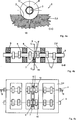
Entsprechend den
Betrachtet man beispielsweise die
In der Darstellung gemäß der
Um eine möglichst leichtgängige Axiallagerung der Nockenwelle
Erfolgt eine Ölzuführung beispielsweise über den Lagerrahmen
Betrachtet man die
Aus der Darstellung gemäß der
Mit der erfindungsgemäßen Axiallagerscheibe
ZITATE ENTHALTEN IN DER BESCHREIBUNG QUOTES INCLUDE IN THE DESCRIPTION
Diese Liste der vom Anmelder aufgeführten Dokumente wurde automatisiert erzeugt und ist ausschließlich zur besseren Information des Lesers aufgenommen. Die Liste ist nicht Bestandteil der deutschen Patent- bzw. Gebrauchsmusteranmeldung. Das DPMA übernimmt keinerlei Haftung für etwaige Fehler oder Auslassungen.This list of the documents listed by the applicant has been generated automatically and is included solely for the better information of the reader. The list is not part of the German patent or utility model application. The DPMA assumes no liability for any errors or omissions.
Zitierte PatentliteraturCited patent literature
- DE 10331089 A1 [0003, 0007] DE 10331089 A1 [0003, 0007]
- DE 102007014544 A1 [0004] DE 102007014544 A1 [0004]
- DE 102009031455 A1 [0005] DE 102009031455 A1 [0005]
- DE 102009049218 A1 [0006] DE 102009049218 A1 [0006]
Claims (10)
Priority Applications (3)
| Application Number | Priority Date | Filing Date | Title |
|---|---|---|---|
| DE102013205129.8A DE102013205129A1 (en) | 2013-03-22 | 2013-03-22 | Bearing frame or cylinder head cover of an internal combustion engine |
| CN201410090661.8A CN104061032B (en) | 2013-03-22 | 2014-03-12 | The bearing support or valve mechanism cover of internal combustion engine |
| US14/222,289 US9512872B2 (en) | 2013-03-22 | 2014-03-21 | Bearing frame or cylinder head cover of an internal combustion engine |
Applications Claiming Priority (1)
| Application Number | Priority Date | Filing Date | Title |
|---|---|---|---|
| DE102013205129.8A DE102013205129A1 (en) | 2013-03-22 | 2013-03-22 | Bearing frame or cylinder head cover of an internal combustion engine |
Publications (1)
| Publication Number | Publication Date |
|---|---|
| DE102013205129A1 true DE102013205129A1 (en) | 2014-09-25 |
Family
ID=51484718
Family Applications (1)
| Application Number | Title | Priority Date | Filing Date |
|---|---|---|---|
| DE102013205129.8A Withdrawn DE102013205129A1 (en) | 2013-03-22 | 2013-03-22 | Bearing frame or cylinder head cover of an internal combustion engine |
Country Status (3)
| Country | Link |
|---|---|
| US (1) | US9512872B2 (en) |
| CN (1) | CN104061032B (en) |
| DE (1) | DE102013205129A1 (en) |
Cited By (4)
| Publication number | Priority date | Publication date | Assignee | Title |
|---|---|---|---|---|
| DE102015006375B3 (en) * | 2015-05-20 | 2016-09-15 | Audi Ag | Internal combustion engine |
| WO2018041698A1 (en) * | 2016-08-29 | 2018-03-08 | Thyssenkrupp Presta Teccenter Ag | Method for mounting an assembled camshaft and cover module |
| EP3557011A1 (en) * | 2018-04-19 | 2019-10-23 | Mahle International GmbH | Bearing frame or cylinder head cover for a combustion engine |
| DE102022208999A1 (en) | 2022-08-30 | 2024-02-29 | Thyssenkrupp Ag | Cylinder head cover, and method for assembling a cylinder head cover |
Families Citing this family (3)
| Publication number | Priority date | Publication date | Assignee | Title |
|---|---|---|---|---|
| DE102013200638A1 (en) * | 2013-01-17 | 2014-07-17 | Mahle International Gmbh | Device for positioning a plurality of functional elements |
| JP6131981B2 (en) * | 2015-03-30 | 2017-05-24 | トヨタ自動車株式会社 | Cam cap |
| DE102020201038A1 (en) * | 2020-01-29 | 2021-07-29 | Mahle International Gmbh | Camshaft arrangement |
Citations (4)
| Publication number | Priority date | Publication date | Assignee | Title |
|---|---|---|---|---|
| DE10331089A1 (en) | 2003-07-09 | 2005-02-24 | Volkswagen Ag | Cylinder head cover for IC engines with one camshaft has bearing bridge with aperture to completely enclose the camshaft |
| DE102007014544A1 (en) | 2007-03-27 | 2008-10-23 | Audi Ag | Internal-combustion engine, has stop element forming axial-bearing that cooperates for axial storage with bearing frame that includes free space for bearing shape of cam, where element is formed by cam of cam shaft |
| DE102009031455A1 (en) | 2009-07-02 | 2011-01-13 | Thyssenkrupp Presta Teccenter Ag | Internal-combustion engine, has housing part provided with recess in which drive wheel is guided in sections such that wheel cooperates with front surface areas of front surfaces and forms axial bearing for shaft |
| DE102009049218A1 (en) | 2009-10-13 | 2011-04-28 | Mahle International Gmbh | Camshaft for an internal combustion engine |
Family Cites Families (18)
| Publication number | Priority date | Publication date | Assignee | Title |
|---|---|---|---|---|
| US2500823A (en) * | 1945-11-10 | 1950-03-14 | Henri J Hickey | Internal-combustion engine |
| DE3206791C2 (en) | 1982-02-25 | 1984-05-10 | Toyota Jidosha Kogyo K.K., Toyota, Aichi | Camshaft assembly |
| JPS6028651U (en) | 1983-08-03 | 1985-02-26 | 日本ピストンリング株式会社 | camshaft |
| JPH0646005B2 (en) * | 1984-06-12 | 1994-06-15 | ヤマハ発動機株式会社 | Bearing structure of valve camshaft |
| DE3431361C2 (en) | 1984-08-25 | 1994-06-23 | Audi Ag | Method of making a built camshaft |
| JP2539260B2 (en) * | 1988-12-03 | 1996-10-02 | マツダ株式会社 | DOHC engine camshaft thrust regulation structure |
| US5778841A (en) * | 1997-02-26 | 1998-07-14 | Cummins Engine Company, Inc. | Camshaft for internal combustion engines |
| JPH11257124A (en) | 1998-03-17 | 1999-09-21 | Suzuki Motor Corp | Thrust bearing structure of camshaft |
| DE19848706A1 (en) * | 1998-10-22 | 2000-04-27 | Schaeffler Waelzlager Ohg | Arrangement for relative movement of camshaft to combustion engine crankshaft has control element as fixed part of adjustable hydraulic valve protruding into hollow chamber |
| JP2001329885A (en) * | 2000-05-18 | 2001-11-30 | Yamaha Motor Co Ltd | Cam angle sensor mounting structure of engine |
| JP4014037B2 (en) * | 2002-09-24 | 2007-11-28 | 本田技研工業株式会社 | OHC internal combustion engine |
| JP4017488B2 (en) * | 2002-09-30 | 2007-12-05 | 本田技研工業株式会社 | Camshaft bearing structure of overhead camshaft internal combustion engine |
| JP4151469B2 (en) | 2003-04-22 | 2008-09-17 | 日産自動車株式会社 | Camshaft rotation angle detection structure |
| DE102006036851A1 (en) | 2005-08-05 | 2007-06-28 | Neumayer Tekfor Holding Gmbh | Cam shaft for internal combustion engine, has base bodies separately manufactured and axially engaged on shaft through sliding, and fixation formed by using ball bearing and provided on bodies |
| US8511269B2 (en) * | 2006-06-07 | 2013-08-20 | Ford Global Technologies | Camshaft system for internal combustion engine |
| DE102007024092A1 (en) | 2007-05-22 | 2008-11-27 | Mahle International Gmbh | camshaft |
| GB2467334A (en) * | 2009-01-30 | 2010-08-04 | Mechadyne Plc | Assembled camshaft for i.c. engines |
| DE102011012149A1 (en) | 2011-02-24 | 2012-09-13 | GM Global Technology Operations LLC (n. d. Ges. d. Staates Delaware) | Cylinder head for internal combustion engine of motor vehicle, has camshaft bearing frame that is arranged on cylinder head housing, where camshaft bearing frame is fixed with central bearing points on cylinder head housing by screws |
-
2013
- 2013-03-22 DE DE102013205129.8A patent/DE102013205129A1/en not_active Withdrawn
-
2014
- 2014-03-12 CN CN201410090661.8A patent/CN104061032B/en not_active Expired - Fee Related
- 2014-03-21 US US14/222,289 patent/US9512872B2/en active Active
Patent Citations (4)
| Publication number | Priority date | Publication date | Assignee | Title |
|---|---|---|---|---|
| DE10331089A1 (en) | 2003-07-09 | 2005-02-24 | Volkswagen Ag | Cylinder head cover for IC engines with one camshaft has bearing bridge with aperture to completely enclose the camshaft |
| DE102007014544A1 (en) | 2007-03-27 | 2008-10-23 | Audi Ag | Internal-combustion engine, has stop element forming axial-bearing that cooperates for axial storage with bearing frame that includes free space for bearing shape of cam, where element is formed by cam of cam shaft |
| DE102009031455A1 (en) | 2009-07-02 | 2011-01-13 | Thyssenkrupp Presta Teccenter Ag | Internal-combustion engine, has housing part provided with recess in which drive wheel is guided in sections such that wheel cooperates with front surface areas of front surfaces and forms axial bearing for shaft |
| DE102009049218A1 (en) | 2009-10-13 | 2011-04-28 | Mahle International Gmbh | Camshaft for an internal combustion engine |
Cited By (8)
| Publication number | Priority date | Publication date | Assignee | Title |
|---|---|---|---|---|
| DE102015006375B3 (en) * | 2015-05-20 | 2016-09-15 | Audi Ag | Internal combustion engine |
| WO2016184557A1 (en) | 2015-05-20 | 2016-11-24 | Audi Ag | Internal combustion engine |
| US10215061B2 (en) | 2015-05-20 | 2019-02-26 | Audi Ag | Internal combustion engine |
| WO2018041698A1 (en) * | 2016-08-29 | 2018-03-08 | Thyssenkrupp Presta Teccenter Ag | Method for mounting an assembled camshaft and cover module |
| EP3557011A1 (en) * | 2018-04-19 | 2019-10-23 | Mahle International GmbH | Bearing frame or cylinder head cover for a combustion engine |
| DE102018205982A1 (en) | 2018-04-19 | 2019-10-24 | Mahle International Gmbh | Bearing frame or cylinder head cover of an internal combustion engine |
| US10961875B2 (en) | 2018-04-19 | 2021-03-30 | Mahle International Gmbh | Bearing frame or cylinder head cover of an internal combustion engine |
| DE102022208999A1 (en) | 2022-08-30 | 2024-02-29 | Thyssenkrupp Ag | Cylinder head cover, and method for assembling a cylinder head cover |
Also Published As
| Publication number | Publication date |
|---|---|
| CN104061032A (en) | 2014-09-24 |
| US9512872B2 (en) | 2016-12-06 |
| CN104061032B (en) | 2017-10-24 |
| US20140299092A1 (en) | 2014-10-09 |
Similar Documents
| Publication | Publication Date | Title |
|---|---|---|
| DE102013205129A1 (en) | Bearing frame or cylinder head cover of an internal combustion engine | |
| EP1995417B1 (en) | Cam shaft | |
| EP1963625B1 (en) | Camshaft | |
| EP2676009B1 (en) | Activation module for at least one gas exchange valve of an internal combustion engine | |
| DE102013207573A1 (en) | Bearing frame or cylinder head cover | |
| DE102011056223B4 (en) | Electrical continuously variable valve timing device | |
| DE102011081483A1 (en) | Method for simplified and precise positioning of a camshaft module on a cylinder head | |
| DE102016216223B4 (en) | Method of assembling a built camshaft | |
| DE102012217456A1 (en) | Camshaft for an internal combustion engine | |
| EP3014145B1 (en) | Adjustable camshaft | |
| DE102012016672A1 (en) | Internal combustion engine has recess engaged in shaft along radial direction of basic camshaft and in bearing recess of bearing, and bearing seats that are arranged between cylinders of engine main portion along axial direction | |
| DE102015224011A1 (en) | Adjustable camshaft | |
| EP2653672B1 (en) | Internal Combustion Engine | |
| EP3250796B1 (en) | Process of assembling a camshaft in a module unit | |
| DE102011001288B4 (en) | Internal combustion engine | |
| EP2744987B1 (en) | Camshaft for the valve train of an internal combustion engine | |
| DE102013218516A1 (en) | Phaser | |
| EP3557011B1 (en) | Bearing frame or cylinder head cover for a combustion engine | |
| DE102016210024A1 (en) | Method for producing a built-up camshaft of an internal combustion engine | |
| EP3165721B1 (en) | Camshaft | |
| DE102012008219A1 (en) | Valve train for combustion engine, has retaining rings clamped in accumulation bevels of basic camshaft, so that additional component is clamped on camshaft, while retaining rings do not contact bottom portions of retaining grooves | |
| DE102013204655A1 (en) | Valve train of an internal combustion engine | |
| DE102016217146A1 (en) | Variable camshaft control | |
| DE102016012320A1 (en) | Method for mounting a valve stem seal, valve train for an internal combustion engine and tool for mounting a valve stem seal | |
| DE102021207293A1 (en) | camshaft plug |
Legal Events
| Date | Code | Title | Description |
|---|---|---|---|
| R163 | Identified publications notified | ||
| R163 | Identified publications notified |
Effective date: 20150108 |
|
| R012 | Request for examination validly filed | ||
| R119 | Application deemed withdrawn, or ip right lapsed, due to non-payment of renewal fee |