DE102012218552B4 - pump - Google Patents
pump Download PDFInfo
- Publication number
- DE102012218552B4 DE102012218552B4 DE102012218552.6A DE102012218552A DE102012218552B4 DE 102012218552 B4 DE102012218552 B4 DE 102012218552B4 DE 102012218552 A DE102012218552 A DE 102012218552A DE 102012218552 B4 DE102012218552 B4 DE 102012218552B4
- Authority
- DE
- Germany
- Prior art keywords
- damper
- cylinder
- fuel
- piston
- pump
- Prior art date
- Legal status (The legal status is an assumption and is not a legal conclusion. Google has not performed a legal analysis and makes no representation as to the accuracy of the status listed.)
- Expired - Fee Related
Links
Images
Classifications
-
- F—MECHANICAL ENGINEERING; LIGHTING; HEATING; WEAPONS; BLASTING
- F04—POSITIVE - DISPLACEMENT MACHINES FOR LIQUIDS; PUMPS FOR LIQUIDS OR ELASTIC FLUIDS
- F04B—POSITIVE-DISPLACEMENT MACHINES FOR LIQUIDS; PUMPS
- F04B53/00—Component parts, details or accessories not provided for in, or of interest apart from, groups F04B1/00 - F04B23/00 or F04B39/00 - F04B47/00
- F04B53/16—Casings; Cylinders; Cylinder liners or heads; Fluid connections
-
- F—MECHANICAL ENGINEERING; LIGHTING; HEATING; WEAPONS; BLASTING
- F02—COMBUSTION ENGINES; HOT-GAS OR COMBUSTION-PRODUCT ENGINE PLANTS
- F02M—SUPPLYING COMBUSTION ENGINES IN GENERAL WITH COMBUSTIBLE MIXTURES OR CONSTITUENTS THEREOF
- F02M53/00—Fuel-injection apparatus characterised by having heating, cooling or thermally-insulating means
-
- F—MECHANICAL ENGINEERING; LIGHTING; HEATING; WEAPONS; BLASTING
- F02—COMBUSTION ENGINES; HOT-GAS OR COMBUSTION-PRODUCT ENGINE PLANTS
- F02M—SUPPLYING COMBUSTION ENGINES IN GENERAL WITH COMBUSTIBLE MIXTURES OR CONSTITUENTS THEREOF
- F02M55/00—Fuel-injection apparatus characterised by their fuel conduits or their venting means; Arrangements of conduits between fuel tank and pump F02M37/00
- F02M55/04—Means for damping vibrations or pressure fluctuations in injection pump inlets or outlets
-
- F—MECHANICAL ENGINEERING; LIGHTING; HEATING; WEAPONS; BLASTING
- F02—COMBUSTION ENGINES; HOT-GAS OR COMBUSTION-PRODUCT ENGINE PLANTS
- F02M—SUPPLYING COMBUSTION ENGINES IN GENERAL WITH COMBUSTIBLE MIXTURES OR CONSTITUENTS THEREOF
- F02M59/00—Pumps specially adapted for fuel-injection and not provided for in groups F02M39/00 -F02M57/00, e.g. rotary cylinder-block type of pumps
- F02M59/44—Details, components parts, or accessories not provided for in, or of interest apart from, the apparatus of groups F02M59/02 - F02M59/42; Pumps having transducers, e.g. to measure displacement of pump rack or piston
- F02M59/442—Details, components parts, or accessories not provided for in, or of interest apart from, the apparatus of groups F02M59/02 - F02M59/42; Pumps having transducers, e.g. to measure displacement of pump rack or piston means preventing fuel leakage around pump plunger, e.g. fluid barriers
-
- F—MECHANICAL ENGINEERING; LIGHTING; HEATING; WEAPONS; BLASTING
- F02—COMBUSTION ENGINES; HOT-GAS OR COMBUSTION-PRODUCT ENGINE PLANTS
- F02M—SUPPLYING COMBUSTION ENGINES IN GENERAL WITH COMBUSTIBLE MIXTURES OR CONSTITUENTS THEREOF
- F02M2200/00—Details of fuel-injection apparatus, not otherwise provided for
- F02M2200/31—Fuel-injection apparatus having hydraulic pressure fluctuations damping elements
- F02M2200/315—Fuel-injection apparatus having hydraulic pressure fluctuations damping elements for damping fuel pressure fluctuations
Landscapes
- Engineering & Computer Science (AREA)
- Mechanical Engineering (AREA)
- General Engineering & Computer Science (AREA)
- Chemical & Material Sciences (AREA)
- Combustion & Propulsion (AREA)
- Fuel-Injection Apparatus (AREA)
Abstract
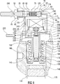
Pumpe (10) für ein Einspritzsystem einer Brennkraftmaschine mit einem Pumpengehäuse (15), – wobei das Pumpengehäuse (15) eine Kraftstoffzuleitung (55, 215) zur Förderung von Kraftstoff (240) umfasst, – wobei in dem Pumpengehäuse (15) ein Zylinder (120) und ein im Zylinder (120) beweglich angeordneter Hubkolben (125) vorgesehen sind, wobei der Hubkolben (125) ausgelegt ist, den Kraftstoff (240) über die Kraftstoffzuleitung (55, 215) anzusaugen und zu verdichten, wobei – ein hydraulisches Dämpferelement (60) zum Ausgleichen von Druckschwankungen in dem Kraftstoff (24) vorgesehen ist, – wobei das Dämpferelement (60) mit der Kraftstoffzuleitung (55, 215) verbunden ist, – wobei das Dämpferelement (60) im Pumpengehäuse (15) angeordnet ist, – das Dämpferelement (60) einen Dämpferzylinder (75) mit einer Längsachse (70) und einen im Dämpfungszylinder (75) angeordneten Dämpferkolben (90) umfasst, der verschiebbar in Richtung der Längsachse im Dämpferzylinder (75) geführt ist, – wobei der Dämpferkolben (90) ein erstes Längsende (96) umfasst, – wobei zwischen dem Dämpferzylinder (75) und dem ersten Längsende (96) des Dämpferkolbens (90) ein erster Dämpferraum (100) ausbildet, – wobei der erste Dämpferraum (100) mit der Kraftstoffleitung (55) verbunden ist, – wobei der Dämpferkolben (90) an einem zum ersten Längsende (96) gegenüberliegenden zweiten Längsende (116) mit dem Dämpferzylinder (75) einen zweiten Dämpferraum (115) ausbildet, – wobei eine Vorkammer (210) im Pumpengehäuse (15) vorgesehen ist, die mit der Kraftstoffzuleitung (55, 215) und mittels eines Einlassventils (195) mit einer Hochdruckkammer (190) verbunden ist, wobei die Hochdruckkammer (190) durch den Hubkolben (125), den Zylinder (120) und das Einlassventil (195) ausgebildet wird, wobei das Dämpferelement (60) mit der Vorkammer (210) mittels einer Verbindungsleitung (117) verbunden und ausgelegt ist, eine aus der Vorkammer (210) in die Verbindungsleitung (117) eingeleitete Druckschwankung zu dämpfen dadurch gekennzeichnet, dass – der zweite Dämpferraum (115) mit der Verbindungsleitung (117) verbunden ist, – wobei bei Einleitung einer Druckschwankung aus der Verbindungsleitung (117) in den zweiten Dämpferraum (115) der Dämpferkolben (90) in Richtung des ersten Dämpferraums (100) verschiebbar ist.Pump (10) for an injection system of an internal combustion engine having a pump housing (15), - wherein the pump housing (15) comprises a fuel supply line (55, 215) for conveying fuel (240), - wherein in the pump housing (15) a cylinder (15) 120) and in the cylinder (120) movably arranged lifting piston (125) are provided, wherein the lifting piston (125) is adapted to the fuel (240) via the fuel supply line (55, 215) to suck and compress, wherein - a hydraulic damper element (60) is provided for compensating pressure fluctuations in the fuel (24), - wherein the damper element (60) with the fuel supply line (55, 215) is connected, - wherein the damper element (60) in the pump housing (15) is arranged, - the damper element (60) comprises a damper cylinder (75) with a longitudinal axis (70) and a damper piston (90) arranged in the damping cylinder (75), which is displaceable in the direction of the longitudinal axis in the damper cylinder (75) wherein the damper piston (90) comprises a first longitudinal end (96), wherein between the damper cylinder (75) and the first longitudinal end (96) of the damper piston (90) a first damper space (100) is formed, Damper chamber (100) is connected to the fuel line (55), - wherein the damper piston (90) at a first longitudinal end (96) opposite the second longitudinal end (116) with the damper cylinder (75) forms a second damper space (115), - a pre-chamber (210) is provided in the pump housing (15) which is connected to the fuel supply line (55, 215) and by means of an inlet valve (195) to a high pressure chamber (190), the high pressure chamber (190) through the reciprocating piston (125) , the cylinder (120) and the inlet valve (195) are formed, wherein the damper element (60) is connected to the prechamber (210) by means of a connecting line (117) and adapted to move one of the prechamber (210) into the connecting line (11 7) introduced pressure fluctuation characterized in that - the second damper chamber (115) with the connecting line (117) is connected, - wherein upon initiation of a pressure fluctuation from the connecting line (117) in the second damper chamber (115) of the damper piston (90) in the direction of the first damper chamber (100) is displaceable.
Description
Die Erfindung betrifft eine Pumpe für ein Einspritzsystem einer Brennkraftmaschine mit einem Pumpengehäuse, wobei das Pumpengehäuse eine Kraftstoffzuleitung zur Förderung von Kraftstoff umfasst, wobei in dem Pumpengehäuse ein Zylinder und ein im Zylinder beweglich angeordneter Hubkolben vorgesehen sind, wobei der Hubkolben ausgelegt ist, den Kraftstoff über die Kraftstoffzuleitung anzusaugen und zu verdichten.The invention relates to a pump for an injection system of an internal combustion engine having a pump housing, wherein the pump housing comprises a fuel supply for conveying fuel, wherein in the pump housing, a cylinder and a cylinder movably arranged in the reciprocating piston are provided, wherein the reciprocating piston is designed, the fuel over to suck in and compress the fuel supply line.
Es sind Hochdruckpumpen für ein Einspritzsystem beispielsweise aus der
Ferner sind Dämpferelemente bekannt, um Druckpulsationen in einer Zuleitung der Hochdruckpumpe zu dämpfen. Das Dämpferelement erfordert zusätzliche Bauelemente, um dieses in einem Kraftfahrzeug zu fixieren, auch zusätzlichen Bauraum.Furthermore, damper elements are known to dampen pressure pulsations in a supply line of the high-pressure pump. The damper element requires additional components to fix this in a motor vehicle, also additional space.
Es ist Aufgabe der Erfindung, eine verbesserte Hochdruckpumpe bereitzustellen.It is an object of the invention to provide an improved high-pressure pump.
Diese Aufgabe wird anhand der Merkmale des Anspruchs 1 gelöst. Vorteilhafte Ausführungsformen sind in den abhängigen Ansprüchen angegeben.This object is achieved by the features of claim 1. Advantageous embodiments are given in the dependent claims.
Erfindungsgemäß wurde erkannt, dass eine verbesserte Pumpe, insbesondere eine Hochdruckpumpe für ein Einspritzsystem einer Brennkraftmaschine, dadurch bereitgestellt werden kann, dass die Pumpe ein Pumpengehäuse umfasst, wobei das Pumpengehäuse eine Kraftstoffzuleitung zur Förderung von Kraftstoff umfasst. In dem Pumpengehäuse sind ein Zylinder und ein im Zylinder beweglich angeordneter Hubkolben vorgesehen, wobei der Hubkolben den Kraftstoff über die Kraftstoffzuleitung anzusaugen und zu verdichten. Ferner ist ein hydraulisches Dämpferelement zum Ausgleichen von Druckschwankungen in dem Kraftstoff vorgesehen, wobei das Dämpferelement mit der Kraftstoffzuleitung verbunden ist, und wobei das Dämpferelement im Pumpengehäuse angeordnet ist.According to the invention, it has been recognized that an improved pump, in particular a high-pressure pump for an injection system of an internal combustion engine, can be provided in that the pump comprises a pump housing, wherein the pump housing comprises a fuel supply line for conveying fuel. In the pump housing, a cylinder and a cylinder movably arranged in the reciprocating piston are provided, wherein the lifting piston to suck the fuel through the fuel supply line and to compress. Further, a hydraulic damper element for compensating for pressure fluctuations in the fuel is provided, wherein the damper element is connected to the fuel supply line, and wherein the damper element is arranged in the pump housing.
Diese Ausgestaltung ermöglicht eine kompakte Ausbildung einer Hochdruckpumpe, die nur geringe bis keine Druckpulsationen in eine Zuleitung zu der Hochdruckpumpe induziert.This embodiment allows a compact design of a high-pressure pump, which induces little to no pressure pulsations in a supply line to the high-pressure pump.
In einer Ausführungsform der Erfindung ist eine Vorkammer im Pumpengehäuse vorgesehen, die mit der Kraftstoffzuleitung und mittels eines Einlassventils mit einer Hochdruckkammer verbunden ist, wobei die Hochdruckkammer durch den Hubkolben, den Zylinder und das Einlassventil ausgebildet ist. Das Dämpferelement ist mit der Vorkammer mittels einer Verbindungsleitung verbunden und ausgelegt, eine aus der Vorkammer in die Verbindungsleitung eingeleitete Druckschwankung zu dämpfen. Dadurch kann der Bauraumbedarf der Pumpe reduziert werden.In one embodiment of the invention, a pre-chamber is provided in the pump housing, which is connected to the fuel supply line and by means of an inlet valve with a high pressure chamber, wherein the high pressure chamber is formed by the reciprocating piston, the cylinder and the inlet valve. The damper element is connected to the prechamber by means of a connecting line and designed to dampen a pressure fluctuation introduced from the prechamber into the connecting line. As a result, the space requirement of the pump can be reduced.
In einer weiteren Ausführungsform umfasst das Dämpferelement einen Dämpferzylinder mit einer Längsachse und einen im Dämpfungszylinder angeordneten Dämpferkolben, der verschiebbar in Richtung der Längsachse im Dämpferzylinder geführt ist, wobei der Dämpferkolben ein erstes Längsende umfasst, und wobei zwischen dem Dämpferzylinder und dem ersten Längsende des Dämpferkolbens ein erster Dämpferraum ausgebildet ist. Ferner ist der erste Dämpferraum mit der Kraftstoffleitung verbunden, wobei der Dämpferkolben an einem zum ersten Längsende gegenüberliegenden zweiten Längsende mit dem Dämpferzylinder einen zweiten Dämpferraum ausbildet, wobei der zweite Dämpferraum mit der Verbindungsleitung verbunden ist. Bei Einleitung einer Druckschwankung aus der Verbindungsleitung in den zweiten Dämpferraum ist der Dämpferkolben in Richtung des ersten Druckraums verschiebbar. Diese Ausgestaltung bildet auf einfache Weise einen Dämpfer aus, der ohne gasgefüllte Kammern auskommt.In a further embodiment, the damper element comprises a damper cylinder having a longitudinal axis and a damper piston arranged in the damping cylinder, which is displaceably guided in the direction of the longitudinal axis in the damper cylinder, wherein the damper piston comprises a first longitudinal end, and wherein between the damper cylinder and the first longitudinal end of the damper piston first damper space is formed. Further, the first damper space is connected to the fuel line, wherein the damper piston forms a second damper space with the damper cylinder at a second longitudinal end opposite the first longitudinal end, wherein the second damper space is connected to the connection line. Upon initiation of a pressure fluctuation from the connecting line into the second damper chamber, the damper piston is displaceable in the direction of the first pressure chamber. This embodiment forms a simple way of a damper, which manages without gas-filled chambers.
In einer weiteren Ausführungsform der Erfindung ist der erste Dämpferraum über eine Drossel mit der Kraftstoffzuleitung verbunden ist, wobei bei einer Verschiebung des Druckkolbens der Kraftstoff über die Drossel in/aus dem ersten Dämpferraum strömt. Auf diese Weise kann wirksam durch eine Bewegung des Dämpferkolbens im ersten Dämpferraum eine Verdrängung bzw. eine Vergrößerung des Volumens des ersten Dämpferraums über einen längeren Zeitraum gestreckt werden, sodass nur ein geringer Druckanstieg und ein langsamer Druckanstieg in die Kraftstoffzuleitung induziert wird.In a further embodiment of the invention, the first damper chamber is connected via a throttle with the fuel supply line, wherein upon displacement of the pressure piston, the fuel flows via the throttle in / out of the first damper chamber. In this way, by displacement of the damper piston in the first damper space, displacement of the volume of the first damper space can be effectively extended over a longer period of time, so that only a small pressure increase and a slow pressure increase are induced in the fuel supply line.
In einer weiteren Ausführungsform ist zwischen dem Dämpferzylinder und dem ersten Längsende des Dämpferkolbens im ersten Dämpferraum ein Federelement, insbesondere eine Spiraldruckfeder, vorgesehen, das den Dämpferkolben mit einer Federkraft in Richtung des zweiten Dämpferraums beaufschlagt. Auf diese Weise wird gewährleistet, dass der Dämpferkolben zurück in eine Ausgangsposition durch das Federelement gedrückt werden kann.In another embodiment, between the damper cylinder and the first Longitudinal end of the damper piston in the first damper chamber, a spring element, in particular a coil compression spring provided, which acts on the damper piston with a spring force in the direction of the second damper chamber. In this way it is ensured that the damper piston can be pushed back into a starting position by the spring element.
In einer weiteren Ausführungsform ist eine im Bereich des Hubkolbens zumindest teilweise um den Hubkolben umfangsseitig umlaufende Nut im Zylinder vorgesehen, die über die Kraftstoffzuleitung mit einem Anschluss der Pumpe verbunden ist. Durch die umlaufende Nut können Leckagen, die zwischen dem Zylinder und dem Hubkolben fließen, aufgefangen werden.In another embodiment, in the region of the piston at least partially around the reciprocating piston circumferentially circumferential groove in the cylinder is provided, which is connected via the fuel supply line with a connection of the pump. Through the circumferential groove leaks that flow between the cylinder and the piston can be collected.
In einer weiteren Ausführungsform ist die umlaufende Nut mittels einer weiteren Kraftstoffzuleitung mit der Vorkammer verbunden. Auf diese Weise kann der durch die umlaufende Nut aufgefangene und erhitzte Kraftstoff direkt verdichtet und aus der Hochdruckpumpe gefördert werden, ohne dass der Kraftstoff abermals in den Kraftstofftank zurückfließt.In a further embodiment, the circumferential groove is connected by means of a further fuel supply line with the prechamber. In this way, the fuel collected and heated by the circumferential groove can be directly compressed and delivered from the high-pressure pump without the fuel flowing back into the fuel tank.
Als besonders vorteilhaft hat sich herausgestellt, wenn die Nut ausgelegt ist, einen Leckagestrom von Kraftstoff zwischen dem Hubkolben und dem Zylinder aus der Hochdruckkammer im Wesentlichen vollständig aufzunehmen und in die weitere Kraftstoffzuleitung einzuleiten. Auf diese Weise wird vermieden, dass der durch die Verdichtung stark erhitzte Kraftstoff wieder zurück in den Kraftstofftank gefördert wird und dort den weiteren Kraftstoff stark erhitzt.To be particularly advantageous has been found when the groove is designed to substantially completely absorb a leakage current of fuel between the reciprocating piston and the cylinder from the high-pressure chamber substantially and to initiate the further fuel supply line. In this way it is avoided that the highly heated by the compression fuel is pumped back into the fuel tank and there strongly heated the other fuel.
In einer weiteren Ausführungsform umfasst der Dämpferzylinder eine Dämpferhülse, die mittels eines Presssitzes umfangsseitig in dem Pumpengehäuse befestigt ist. Auf diese Weise können unterschiedliche Werkstoffe der Dämpferhülse und des Pumpengehäuses je nach entsprechender Anwendung verwendet werden und die Dämpferhülse gleichzeitig zuverlässig im Pumpengehäuse befestigt werden. Ferner kann mittels des Presssitzes auch die Federkraft des Federelements zur Betätigung des Dämpferkolbens einfach festgelegt werden.In a further embodiment, the damper cylinder comprises a damper sleeve, which is attached by means of a press fit circumferentially in the pump housing. In this way, different materials of the damper sleeve and the pump housing can be used depending on the appropriate application and the damper sleeve are reliably fixed in the pump housing at the same time. Furthermore, by means of the interference fit, the spring force of the spring element for actuating the damper piston can also be easily determined.
Als besonders vorteilhaft hat sich herausgestellt, wenn das Pumpengehäuse eine Dämpferbohrung umfasst, in der die Dämpferhülse angeordnet ist, wobei die Dämpferhülse einen Werkstoff aufweist, dessen Oberflächenhärte höher ist als eine Oberflächenhärte des Pumpengehäuses an der Dämpferbohrung.To be particularly advantageous has been found when the pump housing includes a damper bore in which the damper sleeve is arranged, wherein the damper sleeve comprises a material whose surface hardness is higher than a surface hardness of the pump housing to the damper bore.
Die oben beschriebenen Eigenschaften, Merkmale und Vorteile dieser Erfindung sowie die Art und Weise, wie diese erreicht werden, werden klarer und deutlicher verständlich im Zusammenhang mit der folgenden Beschreibung der Ausführungsbeispiele, die im Zusammenhang mit den Zeichnungen näher erläutert werden, wobeiThe above-described characteristics, features, and advantages of this invention, as well as the manner in which they are achieved, will become clearer and more clearly understood in connection with the following description of the embodiments which will be described in connection with the drawings
Die Hochdruckpumpe
Gegenüberliegend zum ersten Dämpferraum
In den Zylinderabschnitt
Der Antriebsabschnitt
Der Zylinderabschnitt
In dem Zylinderaufnahmeabschnitt
Der Zylinderabschnitt
Die Hochdruckkammer
Im Folgenden soll auf die Funktionsweise der Hochdruckpumpe
Ein Kraftstoff
Befindet sich der Hubkolben
Während des Verdichtens des Kraftstoffs
Durch die Hub- und Senkbewegung des Hubkolbens
Nach dem Dämpfen der Druckpulsation befördert das Federelement
Durch die in
Obwohl die Erfindung im Detail durch das bevorzugte Ausführungsbeispiel näher illustriert und beschrieben wurde, so ist die Erfindung nicht durch die offenbarten Beispiele eingeschränkt und andere Variationen können vom Fachmann hieraus abgeleitet werden, ohne den Schutzumfang der Erfindung zu verlassen.Although the invention has been further illustrated and described in detail by the preferred embodiment, the invention is not limited by the disclosed examples, and other variations can be derived therefrom by those skilled in the art without departing from the scope of the invention.
So ist beispielsweise denkbar, dass die erste Kraftstoffzuleitung
Ferner ist auch denkbar, dass statt der Nut
Auch ist denkbar, dass die Verbindungsleitung
BezugszeichenlisteLIST OF REFERENCE NUMBERS
- 1010
- Hochdruckpumpehigh pressure pump
- 1515
- Pumpengehäusepump housing
- 2020
- Aktorabschnittactuator section
- 2525
- Zylinderabschnittcylinder section
- 3030
- Antriebsabschnittdriving section
- 3535
- Zulaufkanalinlet channel
- 4040
- Innengewindeinner thread
- 4545
- Anschlussstückconnector
- 5050
- Dichtelementsealing element
- 5555
- erste Kraftstoffzuleitungfirst fuel supply line
- 6060
- Dämpferelementdamper element
- 6565
- Dämpferbohrungdamper hole
- 7070
- Längsachselongitudinal axis
- 7575
- Dämpferhülsedamper sleeve
- 8080
- Bodenground
- 8585
- Drosselthrottle
- 9090
- Dämpferkolbendamper piston
- 9595
- SeitenwandSide wall
- 9696
- erstes Längsende des Dämpferkolbensfirst longitudinal end of the damper piston
- 100100
- erster Dämpferraumfirst damper room
- 105105
- Federelementspring element
- 110110
- Absatzparagraph
- 115115
- zweiter Dämpferraumsecond damper room
- 116116
- zweites Längsendesecond longitudinal end
- 117117
- Verbindungsleitungconnecting line
- 120120
- Zylindercylinder
- 125125
- Hubkolbenreciprocating
- 130130
- Betätigungseinrichtungactuator
- 135135
- Nockecam
- 140140
- Rollenstößelroller plunger
- 145145
- Druckfedercompression spring
- 150150
- erstes Längsende der Druckfederfirst longitudinal end of the compression spring
- 155155
- zweites Längsende der Druckfedersecond longitudinal end of the compression spring
- 160160
- ZylinderführungsraumCylinder guide space
- 165165
- ZylinderführungsabschnittCylinder guide section
- 170170
- Dichtflächesealing surface
- 175175
- ZylinderaufnahmeabschnittCylinder receiving section
- 180180
- Dichtelementsealing element
- 185185
- Nutgroove
- 190190
- HochdruckkammerHigh-pressure chamber
- 191191
- erste Stirnflächefirst end face
- 195195
- Einlassventilintake valve
- 200200
- Aktoractuator
- 205205
- Ventilsitzvalve seat
- 210210
- Vorkammerantechamber
- 215215
- zweite Kraftstoffzuleitungsecond fuel supply line
- 220220
- Anschlussconnection
- 225225
- Auslassleitungoutlet pipe
- 230230
- Auslassventiloutlet valve
- 235235
- RailRail
- 240240
- Kraftstofffuel
Claims (8)
Priority Applications (1)
| Application Number | Priority Date | Filing Date | Title |
|---|---|---|---|
| DE102012218552.6A DE102012218552B4 (en) | 2012-10-11 | 2012-10-11 | pump |
Applications Claiming Priority (1)
| Application Number | Priority Date | Filing Date | Title |
|---|---|---|---|
| DE102012218552.6A DE102012218552B4 (en) | 2012-10-11 | 2012-10-11 | pump |
Publications (2)
| Publication Number | Publication Date |
|---|---|
| DE102012218552A1 DE102012218552A1 (en) | 2014-04-17 |
| DE102012218552B4 true DE102012218552B4 (en) | 2016-03-24 |
Family
ID=50383146
Family Applications (1)
| Application Number | Title | Priority Date | Filing Date |
|---|---|---|---|
| DE102012218552.6A Expired - Fee Related DE102012218552B4 (en) | 2012-10-11 | 2012-10-11 | pump |
Country Status (1)
| Country | Link |
|---|---|
| DE (1) | DE102012218552B4 (en) |
Cited By (1)
| Publication number | Priority date | Publication date | Assignee | Title |
|---|---|---|---|---|
| DE102018215132A1 (en) * | 2018-09-06 | 2020-03-12 | Ford Global Technologies, Llc | High pressure pump for a fuel supply to an internal combustion engine |
Families Citing this family (5)
| Publication number | Priority date | Publication date | Assignee | Title |
|---|---|---|---|---|
| DE102014217388A1 (en) * | 2014-09-01 | 2016-03-03 | Robert Bosch Gmbh | High-pressure fuel pump, in particular for a fuel injection device of an internal combustion engine |
| DE102017204843B3 (en) | 2017-03-22 | 2018-06-28 | Continental Automotive Gmbh | High-pressure fuel-plug-in pump for a fuel injection system |
| GB2561189A (en) * | 2017-04-04 | 2018-10-10 | Delphi Int Operations Luxembourg Sarl | Piezo controlled inlet valve |
| IT201700065545A1 (en) * | 2017-06-13 | 2018-12-13 | Bosch Gmbh Robert | PUMP UNIT FOR FUEL SUPPLY TO AN INTERNAL COMBUSTION ENGINE |
| DE102017213891B3 (en) * | 2017-08-09 | 2019-02-14 | Continental Automotive Gmbh | High-pressure fuel pump for a fuel injection system |
Citations (4)
| Publication number | Priority date | Publication date | Assignee | Title |
|---|---|---|---|---|
| DE10156428A1 (en) * | 2001-11-16 | 2003-06-12 | Bosch Gmbh Robert | Fuel-cooled pump element and high-pressure pump for a fuel injection system |
| DE102009000357A1 (en) * | 2008-01-22 | 2009-07-23 | Denso Corporation, Kariya | Kraftstofffpumpe |
| DE102008018018A1 (en) * | 2008-04-09 | 2009-10-15 | Continental Automotive Gmbh | Pump for conveying a fluid |
| DE102010064189A1 (en) * | 2010-12-27 | 2012-06-28 | Robert Bosch Gmbh | Pump of a fuel injector |
-
2012
- 2012-10-11 DE DE102012218552.6A patent/DE102012218552B4/en not_active Expired - Fee Related
Patent Citations (4)
| Publication number | Priority date | Publication date | Assignee | Title |
|---|---|---|---|---|
| DE10156428A1 (en) * | 2001-11-16 | 2003-06-12 | Bosch Gmbh Robert | Fuel-cooled pump element and high-pressure pump for a fuel injection system |
| DE102009000357A1 (en) * | 2008-01-22 | 2009-07-23 | Denso Corporation, Kariya | Kraftstofffpumpe |
| DE102008018018A1 (en) * | 2008-04-09 | 2009-10-15 | Continental Automotive Gmbh | Pump for conveying a fluid |
| DE102010064189A1 (en) * | 2010-12-27 | 2012-06-28 | Robert Bosch Gmbh | Pump of a fuel injector |
Cited By (1)
| Publication number | Priority date | Publication date | Assignee | Title |
|---|---|---|---|---|
| DE102018215132A1 (en) * | 2018-09-06 | 2020-03-12 | Ford Global Technologies, Llc | High pressure pump for a fuel supply to an internal combustion engine |
Also Published As
| Publication number | Publication date |
|---|---|
| DE102012218552A1 (en) | 2014-04-17 |
Similar Documents
| Publication | Publication Date | Title |
|---|---|---|
| DE102012218552B4 (en) | pump | |
| EP1727983B1 (en) | High-pressure pump, in particular for a fuel-injection device in an internal combustion engine | |
| DE10118754B4 (en) | high pressure pump | |
| WO2006069818A1 (en) | Piston pump, particularly a high-pressure fuel pump for an internal combustion engine | |
| DE102012204264A1 (en) | high pressure pump | |
| DE102012202720A1 (en) | high pressure pump | |
| DE102009000857A1 (en) | Pump arrangement for use in fuel injection system of air-compressed, self-igniting internal combustion engine, has suction valve for filling pump operating chamber of pump component with diesel fuel from recess of housing | |
| WO2009115353A1 (en) | High-pressure pump | |
| DE112009001971T5 (en) | Check valve with separate spherical spring guide | |
| DE102004056665A1 (en) | Method, computer program and control and / or regulating device for operating an internal combustion engine, and internal combustion engine | |
| DE102008001890A1 (en) | High-pressure pump i.e. radial or tandem piston pump, for fuel i.e. diesel, injection system of air compressed, self ignition internal combustion engine, has aligning element for aligning tappet body in orientation at area | |
| DE102013219284A1 (en) | Pump, in particular high-pressure fuel pump for a fuel injection device of an internal combustion engine | |
| DE10141679A1 (en) | Fuel injection device for an internal combustion engine | |
| DE102013225418A1 (en) | Method for operating a high-pressure fuel pump of a fuel injection device of an internal combustion engine | |
| DE102008002178A1 (en) | High-pressure pump i.e. radial or row piston pump, for fuel injection system of air-compressing, self-igniting internal-combustion engine, has anti-twist protection pin whose end is intervened in cylinder head | |
| DE102014202571A1 (en) | Pump for conveying a fluid | |
| EP3061967B1 (en) | Pump, in particular high-pressure fuel pump | |
| DE102013209760A1 (en) | pump | |
| EP1275843A2 (en) | Internal combustion engine for motor vehicle | |
| DE102013207771A1 (en) | Pump, in particular fuel pump | |
| DE102008043839A1 (en) | High pressure pump, particularly fuel pump for fuel injection units of air compression, self igniting internal combustion engines, comprises pump assembly which has pump piston and pump working chamber that is limited by pump piston | |
| DE102013216983A1 (en) | pump | |
| DE102009001116A1 (en) | High-pressure piston pump for fuel injecting mechanism of internal-combustion engine of motor vehicle, has pump piston, roller shoes and idler rollers combinations held by holder, which overlaps combinations and pretensions against track | |
| DE102008007342A1 (en) | Shear force-free cams for common-rail high-pressure pumps | |
| DE102012007125A1 (en) | Radial piston pump for fuel delivery in fuel injection system of internal combustion engine, has annular chamber containing opening that contains optionally available or freely available substances |
Legal Events
| Date | Code | Title | Description |
|---|---|---|---|
| R012 | Request for examination validly filed | ||
| R079 | Amendment of ipc main class |
Free format text: PREVIOUS MAIN CLASS: F02M0059440000 Ipc: F02M0055040000 |
|
| R016 | Response to examination communication | ||
| R016 | Response to examination communication | ||
| R018 | Grant decision by examination section/examining division | ||
| R020 | Patent grant now final | ||
| R081 | Change of applicant/patentee |
Owner name: VITESCO TECHNOLOGIES GMBH, DE Free format text: FORMER OWNER: CONTINENTAL AUTOMOTIVE GMBH, 30165 HANNOVER, DE |
|
| R084 | Declaration of willingness to licence | ||
| R081 | Change of applicant/patentee |
Owner name: VITESCO TECHNOLOGIES GMBH, DE Free format text: FORMER OWNER: VITESCO TECHNOLOGIES GMBH, 30165 HANNOVER, DE |
|
| R119 | Application deemed withdrawn, or ip right lapsed, due to non-payment of renewal fee |