DE102012202480B4 - Media rotation and displacement mechanism - Google Patents

Media rotation and displacement mechanism Download PDF

Info

Publication number
DE102012202480B4
DE102012202480B4 DE102012202480.8A DE102012202480A DE102012202480B4 DE 102012202480 B4 DE102012202480 B4 DE 102012202480B4 DE 102012202480 A DE102012202480 A DE 102012202480A DE 102012202480 B4 DE102012202480 B4 DE 102012202480B4
Authority
DE
Germany
Prior art keywords
sets
disks
disc
orientation
discs
Prior art date
Legal status (The legal status is an assumption and is not a legal conclusion. Google has not performed a legal analysis and makes no representation as to the accuracy of the status listed.)
Expired - Fee Related
Application number
DE102012202480.8A
Other languages
German (de)
Other versions
DE102012202480A1 (en
Inventor
Derek A. Bryl
Adam D. Ledgerwood
Aaron M. Moore
Matthew M. Storey
Current Assignee (The listed assignees may be inaccurate. Google has not performed a legal analysis and makes no representation or warranty as to the accuracy of the list.)
Xerox Corp
Original Assignee
Xerox Corp
Priority date (The priority date is an assumption and is not a legal conclusion. Google has not performed a legal analysis and makes no representation as to the accuracy of the date listed.)
Filing date
Publication date
Application filed by Xerox Corp filed Critical Xerox Corp
Publication of DE102012202480A1 publication Critical patent/DE102012202480A1/en
Application granted granted Critical
Publication of DE102012202480B4 publication Critical patent/DE102012202480B4/en
Expired - Fee Related legal-status Critical Current
Anticipated expiration legal-status Critical

Links

Images

Classifications

    • BPERFORMING OPERATIONS; TRANSPORTING
    • B65CONVEYING; PACKING; STORING; HANDLING THIN OR FILAMENTARY MATERIAL
    • B65HHANDLING THIN OR FILAMENTARY MATERIAL, e.g. SHEETS, WEBS, CABLES
    • B65H9/00Registering, e.g. orientating, articles; Devices therefor
    • B65H9/16Inclined tape, roller, or like article-forwarding side registers
    • BPERFORMING OPERATIONS; TRANSPORTING
    • B65CONVEYING; PACKING; STORING; HANDLING THIN OR FILAMENTARY MATERIAL
    • B65HHANDLING THIN OR FILAMENTARY MATERIAL, e.g. SHEETS, WEBS, CABLES
    • B65H2403/00Power transmission; Driving means
    • B65H2403/20Belt drives
    • B65H2403/21Timing belts
    • BPERFORMING OPERATIONS; TRANSPORTING
    • B65CONVEYING; PACKING; STORING; HANDLING THIN OR FILAMENTARY MATERIAL
    • B65HHANDLING THIN OR FILAMENTARY MATERIAL, e.g. SHEETS, WEBS, CABLES
    • B65H2403/00Power transmission; Driving means
    • B65H2403/40Toothed gearings
    • B65H2403/48Other
    • B65H2403/484Speed reducers
    • BPERFORMING OPERATIONS; TRANSPORTING
    • B65CONVEYING; PACKING; STORING; HANDLING THIN OR FILAMENTARY MATERIAL
    • B65HHANDLING THIN OR FILAMENTARY MATERIAL, e.g. SHEETS, WEBS, CABLES
    • B65H2404/00Parts for transporting or guiding the handled material
    • B65H2404/20Belts
    • B65H2404/25Driving or guiding arrangements
    • BPERFORMING OPERATIONS; TRANSPORTING
    • B65CONVEYING; PACKING; STORING; HANDLING THIN OR FILAMENTARY MATERIAL
    • B65HHANDLING THIN OR FILAMENTARY MATERIAL, e.g. SHEETS, WEBS, CABLES
    • B65H2801/00Application field
    • B65H2801/24Post -processing devices
    • B65H2801/27Devices located downstream of office-type machines

Abstract

Dreh- und Verschiebemechanismus zur Verwendung bei der Steuerung der Orientierung und Ausrichtung von Medien, die ein Endbearbeitungstransportmodul durchlaufen, mit:zwei Drehscheibensätzen mit geringem Abstand, über die die Medien laufen; undeiner Laufwalze, die mit jedem der Drehscheibensätze einen Spalt bildet, wobei jeder der Drehscheibensätze mindestens zwei konzentrische Scheiben enthält.A rotating and translating mechanism for use in controlling the orientation and orientation of media traveling through a finishing transport module, comprising: two spaced sets of spinning disks over which the media pass; anda drive roller forming a gap with each of the sets of rotary disks, each of the sets of rotary disks including at least two concentric disks.

Description

Die vorliegende Erfindung betrifft generell ein Endbearbeitungstransportmodulsystem und betrifft insbesondere einen verbesserten Dreh- und Verschiebemechanismus bzw. Rotations- und Translationsmechanismus zur Verwendung bei der Steuerung der Orientierung und Ausrichtung von Blättern, die ein Endbearbeitungstransportmodul durchlaufen.The present invention relates generally to a finishing transport module system and, more particularly, to an improved rotational and translational mechanism for use in controlling the orientation and orientation of sheets passing through a finishing transport module.

Endbearbeitungstransportmodule zum Drehen und Verschieben bzw. zum Rotieren und zum Ausführen einer Translation von Blättern, die das System durchlaufen, sind beispielsweise bekannt aus dem US-Patent 6,811,152 , das hiermit durch Bezugnahme zusammen mit den darin zitierten Druckschriften mit eingeschlossen ist. Ein weiteres Beispiel des Stands der Technik ist in der 1 bekannt, wobei ein Blattdreh- und Verschiebemechanismus für ein Endbearbeitungstransportmodul 10 zwei Drehscheibenmotore 30 und 32 aufweist, die jeweils unabhängig eine Drehscheibe 12 bzw. 14 antreiben. Wenn sich diese in der gleichen Richtung und mit der gleichen Geschwindigkeit drehen, durchläuft das Blatt die Dreheinrichtung wie in einer normalen Spaltanordnung (keine Änderung der Drehung oder der Richtung). Wenn die Motoren sich weiterhin in der gleichen Richtung mit der gleichen Geschwindigkeit drehen, können Steuerwalzen 16 und 18 um den Rand der Scheiben so geschwenkt werden, dass die Innen/Außen-Position eines Blattes ohne Drehung geändert wird. Dies ist günstig, um Blattgruppen in einem Stapler gegeneinander zu versetzen oder um eine Mitte-Rand-Ausrichtung für Endbearbeitungseinrichtungen, die nachgeordnet sind, zu ändern. Um zu wissen, wann das Blatt um den gewünschten Betrag versetzt wurde, gibt es einen Kantensensor bzw. Randsensor 40, der durch eine Führungsschraube positionierbar. Der Führungsschraubenmotor 33 positioniert den Sensor 40 unter einem gegeben Abstand innen/außen für eine Blattgruppe und fährt den Sensor dann in eine neue Position, um die Innen/Außenposition für die nächste Blattgruppe zu erfassen. Für eine Blattdrehung drehen sich die Motoren, die die Drehscheibe steuern, einfach mit unterschiedlichen Geschwindigkeiten. Je größer der Geschwindigkeitsunterschied ist, desto schneller wird das Medium gedreht.Finishing transport modules for rotating and translating and for carrying out a translation of sheets passing through the system are known, for example, from US Pat U.S. Patent 6,811,152 , which is hereby incorporated by reference together with the references cited therein. Another example of the prior art is in 1 a sheet turning and shifting mechanism for a finishing transport module 10 two turntable motors 30 and 32 each having a turntable independently 12 respectively. 14 drive. As these rotate in the same direction and at the same speed, the blade passes through the rotator as in a normal nip arrangement (no change in rotation or direction). If the motors continue to rotate in the same direction at the same speed, control rollers can 16 and 18 swiveling around the edge of the discs so that the inside / outside position of a blade is changed without rotation. This is beneficial to offset groups of sheets in a stacker or to change a center-to-edge orientation for downstream finishers. To know when the sheet has been offset by the desired amount, there is an edge sensor 40 which can be positioned by a guide screw. The lead screw motor 33 positions the sensor 40 at a given distance inside / outside for a leaf group, and then moves the sensor to a new position to detect the inside / outside position for the next leaf group. For a blade rotation, the motors that control the turntable simply rotate at different speeds. The greater the difference in speed, the faster the medium is turned.

Problematisch bei diesem Aufbau ist, dass die Scheiben sich horizontal drehen, während sich die Laufwalzen vertikal drehen. Wenn sich daher die Führungswalze entlang eines breiten Spaltes drehen muss (wie bei normale Spaltkonfigurationen), kann es ein Problem mit der Relativbewegung geben. Die 2 nach dem Stand der Technik zeigt eine Draufsicht eines Aufbaus mit breitem Scheibenspalt, wobei der Aufbau eine Scheibe 45 enthält, die einen Spalt mit einer Führungswalze 46 bildet. Man erkennt, dass, wenn R1 sehr viel kleiner ist als R2, es ein ausgeprägtes Problem mit der Relativbewegung gibt. Dies würde zu einem starken Bedrucken, einem Schlupf, einer unzuverlässigen Drehung und Verschiebung, etc. führen. Um dies zu beheben, wird ein sehr dünner Spalt mit hohem Druck verwendet. Der Hochdruckspalt ist in 1, die den Stand der Technik repräsentiert, gezeigt und enthält einen sehr kleinen Kontaktpunkt oder eine Kontaktrippe 13 zwischen der Scheibe 12 und der Laufwalze 18 und einen Punkt 15 zwischen der Scheibe 14 und der Laufwalze 16. Dadurch wird wirksam die Relativbewegung verhindert, da es im Wesentlichen nur einen Radius gibt, aber der Druck ist sehr hoch. Dieser hohe Druck ist erforderlich, um einen Schlupf zu vermeiden, aber der hohe Druck bewirkt schließlich ein Aufdrucken bzw. eine Markierung auf gewissen Medien, insbesondere auf beschichteten Blättern.The problem with this design is that the discs rotate horizontally while the rollers rotate vertically. Therefore, when the guide roller has to rotate along a wide gap (as in normal gap configurations), there may be a problem with the relative movement. The 2 The prior art shows a top view of a wide disc gap construction, the assembly being a disc 45 Contains a gap with a guide roller 46 forms. One recognizes that, if R1 much smaller than R2 There is a pronounced problem with the relative motion. This would lead to heavy printing, slippage, unreliable rotation and displacement, etc. To remedy this, a very thin gap of high pressure is used. The high pressure nip is in 1 , which represents the prior art, shown and contains a very small contact point or a contact rib 13 between the disc 12 and the roller 18 and a point 15 between the disc 14 and the roller 16 , This effectively prevents the relative movement, since there is essentially only one radius, but the pressure is very high. This high pressure is required to prevent slippage, but the high pressure eventually causes printing or marking on certain media, especially on coated sheets.

Es ist daher eine Aufgabe, die Problematik zu lösen, dass bestehende Endbearbeitungstransportmodulsysteme dazu neigen, gewisse Arten von beschichteten Medien ungewollt zu bedrucken bzw. zu markieren.It is therefore an object to solve the problem that existing finishing transport module systems tend to unwantedly mark certain types of coated media.

Folglich besteht eine Lösung der zuvor genannten Problematik darin, dass ein hierin offenbarter verbesserter Dreh/Verschiebe-Mechanismus bzw. Rotations/Translationsmechanismus bereitgestellt wird, der mehrere dünne Scheiben aufweist, die mit einer Laufwalze in Eingriff sind, um den Spaltdruck zu verteilen und um mit unterschiedlichen Drehgeschwindigkeiten zu drehen, so dass die gleiche lineare Geschwindigkeit an dem Spalt hervorgerufen wird, wodurch die Problematik des unerwünschten Druckens gelöst oder zumindest deutlich reduziert wird.

  • 1 ist ein Teilvorderansicht eines bekannten Blattdreh-Verschiebemechanismus zur Verwendung in einem Endbearbeitungstransportmodul;
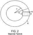
  • 2 ist eine Teildraufsicht einer bekannten Scheiben/Laufwalzen-Spaltkonfiguration;
  • 3 ist eine perspektivische Teilansicht eines verbesserten Blattdreh/Verschiebemechanismus gemäß der vorliegenden Erfindung; und
  • 4 ist eine Frontalteilansicht des verbesserten Blattdreh-Verschiebemechanismus, der in 3 gezeigt ist.
Thus, one solution to the aforementioned problem is to provide an improved rotary / translational mechanism disclosed herein having a plurality of thin discs engaged with a roller for distributing and splitting the nip pressure to rotate at different rotational speeds, so that the same linear velocity is caused at the gap, whereby the problem of undesired printing is solved or at least significantly reduced.
  • 1 Fig. 11 is a partial front view of a known blade rotation displacement mechanism for use in a finishing transport module;
  • 2 Fig. 12 is a partial plan view of a known disk / idler gap configuration;
  • 3 Fig. 13 is a partial perspective view of an improved blade rotation / displacement mechanism according to the present invention; and
  • 4 FIG. 12 is a front partial view of the improved blade rotation shifting mechanism incorporated in FIG 3 is shown.

Es sei nun auf die Zeichnungen verwiesen, wobei diese zum Zwecke des Darstellens einer anschaulichen Ausführungsform bereitgestellt sind, und keine Beschränkung sein sollen, wobei 3 eine perspektivische Teilansicht eines verbesserten Blatt-Dreh-Verschiebemechanismus gemäß der vorliegenden Erfindung zeigt, um die Blattdrehung und die Verschiebung in einem Bearbeitungstransportmodulsystem zu erreichen.Reference is now made to the drawings, which are provided for the purpose of illustrating an illustrative embodiment, and are not intended to be limiting 3 FIG. 4 shows a partial perspective view of an improved sheet-turning and sliding mechanism in accordance with the present invention for achieving sheet rotation and displacement in a processing transport module system.

In einer Reihe von bestehenden Endbearbeitungstransportmodulsystemen wird ein Mediendreh- und Verschiebemechanismus bzw. ein Medienrotations- und Translationsmechanismus bereitgestellt, in welchem zwei Scheiben/Laufwalzenpaare für das erneute Ausrichten transportierter Blätter von der Mitte zur Seite verwendet werden. Jedoch ist der Spalt zwischen der Scheibe und der Laufwalze relativ klein im Vergleich zum Durchmesser der Scheibe, um einen Schlupf zu vermeiden, und der resultierende hohe Spaltendruck bewirkt ein Bedrucken oder Markierungen auf beschichteten Medien. Gemäß der vorliegenden Erfindung wird die einzelne dünne Scheibe durch mehrere konzentrische dünne Scheiben ersetzt, die den Spaltendruck verteilen und sich mit unterschiedlichen Drehgeschwindigkeiten drehen, so dass die gleiche Lineargeschwindigkeit an dem Spalt hervorgerufen wird, wodurch das Markieren von beschichteten Medien reduziert wird. Wie in den 3 und 4 gezeigt ist, umfasst ein Blattdreh/Verschiebemechanismus bzw. Blattrotations/Translationsmechanismus 100 mindestens zwei Scheiben, die mit einer Laufwalze bzw. Führungswalze einen Spalt bilden. Die Scheiben besitzen jeweils einen dünnen Grad oder einen kleinen Kontaktpunkt zwischen den Scheiben und der Laufwalze, wobei mit zunehmender Anzahl der Kontaktpunkte der Druck an jedem Kontaktpunkt abnimmt. Es können auch mehr als zwei Scheiben verwendet werden, falls dies gewünscht ist. Mit jeder hinzugefügten Scheibe wird ein anderer Radius für den Kontakt eingeführt. Daher können die Scheiben nicht mit der gleichen Geschwindigkeit drehen oder es tritt wiederum die Problematik einer unterschiedlichen Geschwindigkeit für die Linearbewegung des Mediums auf. Um das Hinzufügen weiterer Motoren zu vermeiden, werden die zusätzlichen Scheiben oder die zusätzliche Scheibe von dem gleichen Antriebsmotor aus mit entsprechender Übersetzung angetrieben, um die unterschiedlichen Radien zu kompensieren.In a number of existing finishing transport module systems, there is provided a media rotating and shifting mechanism and media rotation and translation mechanism in which two pairs of disks / pairs of rollers are used for reorienting transported sheets from center to side. However, the gap between the disk and the idler roll is relatively small compared to the diameter of the disk to avoid slippage, and the resulting high nip pressure causes printing or marks on coated media. In accordance with the present invention, the single thin disk is replaced by a plurality of concentric thin disks which distribute the nip pressure and rotate at different rotational speeds to cause the same linear velocity at the nip, thereby reducing the marking of coated media. As in the 3 and 4 1, includes a blade rotation / displacement mechanism 100 at least two discs which form a gap with a roller or guide roller. The discs each have a thin degree or point of contact between the discs and the roller, and as the number of contact points increases, the pressure at each point of contact decreases. It is also possible to use more than two discs, if desired. With each added disk, another radius is introduced for the contact. Therefore, the discs can not rotate at the same speed or again the problem of a different speed for the linear movement of the medium occurs. To avoid the addition of additional motors, the additional discs or the additional disc are driven by the same drive motor with appropriate translation to compensate for the different radii.

D. h., innere Scheiben 105 und 101, die in einer Plattform 110 gehalten sind, werden an den Motorwellen 121 und 126 montiert und zum Antrieb mit den Motoren 120 und 125 entsprechend verbunden. Das Getriebe bzw. das Zahnrad 130 ist direkt an der Motorwelle 131 montiert, während das Zahnrad 131 direkt an der Motorwelle 126 angebracht ist. Äußere Scheiben 106 und 102 sind an Lagern montiert und können sich daher frei um die jeweilige Motorwelle 121 bzw. 126 drehen. Die äußeren Scheiben 106 und 102 sind entsprechend an den Zahnrädern 132 bzw. 133 angebracht. Schließlich sind externe Wellen 138 und 139 an Zahnrädern (134, 136) und (135, 137) entsprechend befestigt. Wie in 4 gezeigt ist, treiben die Zahnräder 130 und 131 über Riemen 140, 142, 144 und 146 die externen Wellenlängen 138 und 139 an, die wiederum die Zahnräder (134, 136) und (135, 137) und die äußeren Scheiben 106 und 102 antreiben. Die externen Wellen 138 und 139 ermöglichen die erforderlichen Geschwindigkeitseinstellungen, so dass die inneren und äußeren Scheibensätze sich mit unterschiedlicher Geschwindigkeit jedoch mit übereinstimmender Lineargeschwindigkeit drehen. Wenn somit Papier durch den Spalt geführt wird, gibt es keine Problematik der Relativbewegung, wobei dies unabhängig von der Motorgeschwindigkeit oder der Spaltposition ist, wobei dennoch der Druck an jedem Kontaktpunkt reduziert ist und ein unerwünschtes Drucken bzw. Markieren vermieden wird.That is, inner discs 105 and 101 in a platform 110 are held on the motor shafts 121 and 126 mounted and to drive with the motors 120 and 125 connected accordingly. The gear or the gear 130 is directly on the motor shaft 131 mounted while the gear 131 directly on the motor shaft 126 is appropriate. Outer discs 106 and 102 are mounted on bearings and can therefore freely around the respective motor shaft 121 respectively. 126 rotate. The outer discs 106 and 102 are corresponding to the gears 132 respectively. 133 appropriate. Finally, external waves 138 and 139 on gears ( 134 . 136 ) and ( 135 . 137 ) attached accordingly. As in 4 shown, drive the gears 130 and 131 over straps 140 . 142 . 144 and 146 the external wavelengths 138 and 139 which, in turn, the gears ( 134 . 136 ) and ( 135 . 137 ) and the outer discs 106 and 102 drive. The external waves 138 and 139 allow the required speed settings so that the inner and outer sets of disks rotate at different speeds but at the same linear velocity. Thus, as paper is passed through the nip, there is no problem with relative motion, regardless of engine speed or nip position, yet the pressure at each contact point is reduced and undesirable marking is avoided.

Erfindungsgemäß wird somit ein verbesserter Dreh/Verschiebemechanismus bereitgestellt zur Verwendung in einem Endbearbeitungstransportmodulsystem, das mehrere dünne Scheiben aufweist, die mit einer Laufwalze zusammenwirken, so dass sich ein Spaltdruck verteilt, wobei sich die Scheiben mit unterschiedlichen Drehgeschwindigkeiten drehen, jedoch so, dass die gleiche Lineargeschwindigkeit an dem Spalt hervorgerufen wird, wodurch eine Markierung bzw. unerwünschte Bedruckung von beschichtetem Papier vermieden wird.Thus, according to the present invention, there is provided an improved rotary / translating mechanism for use in a finishing transport module system having a plurality of thin discs cooperating with a roller so as to distribute a nip pressure with the discs rotating at different rotational speeds, but at the same linear velocity is caused at the gap, whereby a marking or unwanted printing of coated paper is avoided.

Claims (10)

Dreh- und Verschiebemechanismus zur Verwendung bei der Steuerung der Orientierung und Ausrichtung von Medien, die ein Endbearbeitungstransportmodul durchlaufen, mit: zwei Drehscheibensätzen mit geringem Abstand, über die die Medien laufen; und einer Laufwalze, die mit jedem der Drehscheibensätze einen Spalt bildet, wobei jeder der Drehscheibensätze mindestens zwei konzentrische Scheiben enthält.A rotating and translating mechanism for use in controlling the orientation and orientation of media passing through a finishing transport module, comprising: two pairs of sets of discs at a small distance, over which the media run; and a rolling roller that forms a gap with each of the sets of rotary disks, each of the sets of rotary disks including at least two concentric disks. Mechanismus nach Anspruch 1, wobei jede der konzentrischen Scheiben eine Kante darauf aufweist, die mit der Laufwalze zusammenwirkt, so dass der Spalt gebildet ist.Mechanism after Claim 1 wherein each of the concentric discs has an edge thereon that cooperates with the roller so that the gap is formed. Mechanismus nach Anspruch 1, wobei jeder der Scheibensätze mehr als zwei Scheiben enthält.Mechanism after Claim 1 wherein each of the pulley sets contains more than two pulleys. Mechanismus nach Anspruch 1, wobei jede Scheibe der Scheibensätze einen anderen Kontaktradius in Bezug auf die Laufwalze besitzt.Mechanism after Claim 1 wherein each disc of the disc sets has a different contact radius with respect to the roller. Mechanismus nach Anspruch 4, wobei eine erste Scheibe eines Scheibensatzes auf einer ersten Welle montiert ist, die mit einem Motor verbunden ist.Mechanism after Claim 4 wherein a first pulley of a pulley set is mounted on a first shaft connected to a motor. Mechanismus nach Anspruch 5, wobei die zweite Scheibe des Scheibensatzes so montiert ist, dass sie frei um die erste Welle rotieren kann.Mechanism after Claim 5 wherein the second disc of the disc set is mounted so that it can rotate freely around the first shaft. Mechanismus nach Anspruch 6, mit einer zweiten Welle, wobei die zweite Scheibe des Scheibensatzes antreibend mit der zweiten Welle verbunden ist.Mechanism after Claim 6 with a second shaft, the second disc of the Pulley set drivingly connected to the second shaft. Mechanismus nach Anspruch 7, wobei die zweite Welle zwei darauf montierte Zahnräder umfasst.Mechanism after Claim 7 wherein the second shaft comprises two gears mounted thereon. Verfahren zum Steuern der Orientierung und Ausrichtung von Medien, die durch ein Endbearbeitungstransportmodul laufen, wobei das Verfahren umfasst: Bereitstellen zweier Drehscheibensätze mit kleinem Abstand, über die die Medien laufen; Bereitstellen einer Laufwalze, die mit jedem der Drehscheibensätze einen Spalt bildet; und Vorsehen von mindestens zwei konzentrischen Scheiben in jedem der Drehscheibensätze.A method of controlling the orientation and orientation of media passing through a finishing transport module, the method comprising: Providing two pairs of sets of small discs over which the media pass; Providing a rolling roller that forms a gap with each of the sets of rotary disks; and Providing at least two concentric disks in each of the sets of rotary disks. Verfahren nach Anspruch 9, das ferner umfasst: Vorsehen einer Kante auf jeder der konzentrischen Scheiben derart, dass diese im Zusammenwirken mit der Laufwalze den Spalt bildet.Method according to Claim 9 further comprising: providing an edge on each of the concentric disks such that it forms the nip in cooperation with the idler roller.
DE102012202480.8A 2011-02-18 2012-02-17 Media rotation and displacement mechanism Expired - Fee Related DE102012202480B4 (en)

Applications Claiming Priority (2)

Application Number Priority Date Filing Date Title
US13/030,503 US8523174B2 (en) 2011-02-18 2011-02-18 Media rotation and translation mechanism
US13/030,503 2011-02-18

Publications (2)

Publication Number Publication Date
DE102012202480A1 DE102012202480A1 (en) 2012-08-23
DE102012202480B4 true DE102012202480B4 (en) 2018-12-20

Family

ID=46605182

Family Applications (1)

Application Number Title Priority Date Filing Date
DE102012202480.8A Expired - Fee Related DE102012202480B4 (en) 2011-02-18 2012-02-17 Media rotation and displacement mechanism

Country Status (3)

Country Link
US (1) US8523174B2 (en)
JP (1) JP5800723B2 (en)
DE (1) DE102012202480B4 (en)

Citations (1)

* Cited by examiner, † Cited by third party
Publication number Priority date Publication date Assignee Title
US6811152B2 (en) 2001-12-21 2004-11-02 C. P. Bourg S.A. Method and device for controlling the orientation and alignment of individual sheets of paper passing on a conveyor

Family Cites Families (4)

* Cited by examiner, † Cited by third party
Publication number Priority date Publication date Assignee Title
US3175824A (en) * 1962-09-07 1965-03-30 Ibm Sheet driving and aligning mechanism
US3218060A (en) * 1963-03-27 1965-11-16 Charles H Harbison Sheet feeding apparatus
US5074546A (en) * 1990-12-20 1991-12-24 Ncr Corporation Bi-directional down drive assembly for a document track
NL1030709C2 (en) * 2005-12-20 2007-06-21 Oce Tech Bv Sheet transport device and printer provided with such a device.

Patent Citations (1)

* Cited by examiner, † Cited by third party
Publication number Priority date Publication date Assignee Title
US6811152B2 (en) 2001-12-21 2004-11-02 C. P. Bourg S.A. Method and device for controlling the orientation and alignment of individual sheets of paper passing on a conveyor

Also Published As

Publication number Publication date
JP2012171796A (en) 2012-09-10
JP5800723B2 (en) 2015-10-28
US20120211938A1 (en) 2012-08-23
DE102012202480A1 (en) 2012-08-23
US8523174B2 (en) 2013-09-03

Similar Documents

Publication Publication Date Title
DE2245901A1 (en) DEVICE FOR CONTINUOUSLY TRANSFERRING A TORQUE
EP0029961A2 (en) Device for turning about a moving web
DE2653173C2 (en) Device for controlling the tension of a material web fed continuously to a machine operating in cycles
DE102012202477B4 (en) Media rotation and displacement device
DE102008048659A1 (en) Apparatus and method for aligning sheets
DE60303970T2 (en) Device for adjusting the width of a paper web
EP2079654B1 (en) Pivotable positioning roller in the reversing winder
DE102009048909A1 (en) Roll feeder, particularly feeding straightener, for conveying or straightening of metal strips, is provided with two rollers which are pivoted and are parallel to each other
DE10111069A1 (en) Folder with combined cutting and clamping cylinder
DE102012202480B4 (en) Media rotation and displacement mechanism
DE2236692A1 (en) SPEED CHANGEABLE DRIVE
DE2554692C2 (en) Device for the production of the magnetic layers of magnetic storage disks
DE2848295C2 (en) Calender for the production of thermoplastic films
EP1177149B1 (en) Device for processing strips of forms
EP3578487B1 (en) Printing machine with a transport device for transporting sheets to be printed
DE2843602C2 (en) Labeling station of a labeling machine for objects, in particular bottles
DE730823C (en) Device for guiding tracks, e.g. B. film webs, long narrow edge strips
DE102013019400B4 (en) Pocket folding station with support element for fold pocket
DE2365924C3 (en) Grinding device for cards or cards
DE2905631C2 (en) Roll stand with at least one support roll surrounded by a loosely rotatable sleeve
DE102006014220A1 (en) Apparatus for slowing down and / or accelerating printed sheets or copies separated from a web-shaped printing substrate
EP1110894B1 (en) Method and device for folding sheets of material
AT500981B1 (en) Buckling
DE2353961A1 (en) CONVEYOR FOLDING UNIT
DE102012205387A1 (en) Magnetically coupled intermediate idler roller

Legal Events

Date Code Title Description
R012 Request for examination validly filed
R082 Change of representative

Representative=s name: GRUENECKER, KINKELDEY, STOCKMAIR & SCHWANHAEUS, DE

Representative=s name: GRUENECKER PATENT- UND RECHTSANWAELTE PARTG MB, DE

R012 Request for examination validly filed

Effective date: 20150216

R018 Grant decision by examination section/examining division
R020 Patent grant now final
R119 Application deemed withdrawn, or ip right lapsed, due to non-payment of renewal fee