DE102012202477B4 - Media rotation and displacement device - Google Patents
Media rotation and displacement device Download PDFInfo
- Publication number
- DE102012202477B4 DE102012202477B4 DE102012202477.8A DE102012202477A DE102012202477B4 DE 102012202477 B4 DE102012202477 B4 DE 102012202477B4 DE 102012202477 A DE102012202477 A DE 102012202477A DE 102012202477 B4 DE102012202477 B4 DE 102012202477B4
- Authority
- DE
- Germany
- Prior art keywords
- rod
- driven
- rollers
- toothing
- roller
- Prior art date
- Legal status (The legal status is an assumption and is not a legal conclusion. Google has not performed a legal analysis and makes no representation as to the accuracy of the status listed.)
- Active
Links
Images


Classifications
-
- B—PERFORMING OPERATIONS; TRANSPORTING
- B65—CONVEYING; PACKING; STORING; HANDLING THIN OR FILAMENTARY MATERIAL
- B65H—HANDLING THIN OR FILAMENTARY MATERIAL, e.g. SHEETS, WEBS, CABLES
- B65H5/00—Feeding articles separated from piles; Feeding articles to machines
- B65H5/06—Feeding articles separated from piles; Feeding articles to machines by rollers or balls, e.g. between rollers
- B65H5/062—Feeding articles separated from piles; Feeding articles to machines by rollers or balls, e.g. between rollers between rollers or balls
-
- B—PERFORMING OPERATIONS; TRANSPORTING
- B65—CONVEYING; PACKING; STORING; HANDLING THIN OR FILAMENTARY MATERIAL
- B65H—HANDLING THIN OR FILAMENTARY MATERIAL, e.g. SHEETS, WEBS, CABLES
- B65H9/00—Registering, e.g. orientating, articles; Devices therefor
- B65H9/16—Inclined tape, roller, or like article-forwarding side registers
- B65H9/166—Roller
-
- B—PERFORMING OPERATIONS; TRANSPORTING
- B65—CONVEYING; PACKING; STORING; HANDLING THIN OR FILAMENTARY MATERIAL
- B65H—HANDLING THIN OR FILAMENTARY MATERIAL, e.g. SHEETS, WEBS, CABLES
- B65H2403/00—Power transmission; Driving means
- B65H2403/40—Toothed gearings
- B65H2403/43—Bevel gearing
-
- B—PERFORMING OPERATIONS; TRANSPORTING
- B65—CONVEYING; PACKING; STORING; HANDLING THIN OR FILAMENTARY MATERIAL
- B65H—HANDLING THIN OR FILAMENTARY MATERIAL, e.g. SHEETS, WEBS, CABLES
- B65H2404/00—Parts for transporting or guiding the handled material
- B65H2404/60—Other elements in face contact with handled material
- B65H2404/69—Other means designated for special purpose
- B65H2404/696—Ball, sphere
- B65H2404/6961—Driving means
-
- B—PERFORMING OPERATIONS; TRANSPORTING
- B65—CONVEYING; PACKING; STORING; HANDLING THIN OR FILAMENTARY MATERIAL
- B65H—HANDLING THIN OR FILAMENTARY MATERIAL, e.g. SHEETS, WEBS, CABLES
- B65H2801/00—Application field
- B65H2801/24—Post -processing devices
- B65H2801/27—Devices located downstream of office-type machines
Abstract
Vorrichtung zum Manipulieren von in einer Ebene geführten Medien, umfassend:ein Paar von zylinderförmigen Antriebsrollen (51, 53), über welche die Medien geführt werden;eine erste Stange (60 und eine zweite Stange (61) jeweils zum Haltern einer jeden Antriebsrolle (51, 53);kugelförmige Walzenrollen (52, 54), die mit jeder zylinderförmigen Antriebsrolle (51, 53) Spalte ausbilden; undeine mit den Stangen (60, 61) verbundene Anordnung zum Drehen der zylinderförmigen Antriebsrollen (51, 52) in horizontalen und vertikalen Ebenen,wobei jede Antriebsrolle (51, 53) mit Zwischenrollen (80, 81) verbunden ist und durch diese angetrieben werden kann,jede Zwischenrolle (80, 81) in Verbindung mit einer ersten kegelförmigen Verzahnung (65, 67) steht,jede erste kegelförmige Verzahnung (65, 67) mit einer zweiten kegelförmigen Verzahnung (64, 66) verbunden ist, so dass sie antreibbar ist, wobei die zweite kegelförmige Verzahnung (64, 66) auf jeder Stange (60, 61) koaxial angeordnet ist, unddie Vorrichtung ferner umfasst: eine mit der zweiten kegelförmigen Verzahnung (64, 66) verbundene erste Stirnradverzahnung (68), welche auf jeder Stange (60, 61) koaxial angeordnet ist, und wobeidie erste und die zweite Stange (60, 61) jeweils drehbar ist und durch einen ersten Motor (M1) angetrieben wird, die erste Stirnradverzahnung (68) auf der zweiten Stange (61) durch einen zweiten Motor (M2) angetrieben wird, und die erste Stirnradverzahnung auf der ersten Stange (60) durch einen dritten Motor (M3) angetrieben wird, so dass Medien in einer horizontalen Ebene führbar sind.Apparatus for manipulating in-plane media, comprising: a pair of cylindrical drive rollers (51, 53) over which the media are guided; a first rod (60 and a second rod (61) each for supporting each drive roller (51 , 53), spherical roller rollers (52, 54) forming gaps with each cylindrical drive roller (51, 53), and an assembly connected to the rods (60, 61) for rotating the cylindrical drive rollers (51, 52) in horizontal and vertical directions Planes, wherein each drive roller (51, 53) is connected to and can be driven by intermediate rollers (80, 81), each intermediate roller (80, 81) is in connection with a first conical toothing (65, 67), each first conical one Gear (65, 67) with a second conical toothing (64, 66) is connected, so that it is drivable, wherein the second conical toothing (64, 66) on each rod (60, 61) is arranged coaxially, anddi The apparatus further comprises: first spur gear teeth (68) connected to said second tapered teeth (64, 66) coaxially disposed on each rod (60, 61) and said first and second rods (60, 61) being respectively rotatable and driven by a first motor (M1), the first spur gear toothing (68) on the second rod (61) is driven by a second motor (M2), and the first spur gear toothing on the first rod (60) by a third motor (M3) is driven, so that media in a horizontal plane are feasible.
Description
Verweis auf zugehörige AnmeldungenReference to related applications
Es wird hiermit Bezug genommen auf die zu dieser Anmeldung korrespondierende anhängige US-Anmeldung
Hintergrundbackground
Gebiet der OffenbarungArea of the revelation
Die vorliegende Offenbarung betrifft im Allgemeinen ein Finisher-Transportmodulsystem und insbesondere eine verbesserte Rotations- bzw. Dreh- und Translations- bzw. Verschiebevorrichtung, welche zur Steuerung der Orientierung und Ausrichtung von Medien verwendet wird, welche durch ein Finisher-Transportmodul geführt werden.The present disclosure generally relates to a finisher transport module system, and more particularly to an improved rotary and translating device used to control the orientation and orientation of media passing through a finisher transport module.
Beschreibung des Stands der TechnikDescription of the Related Art
Finisher-Transportmodulsysteme zum Drehen und Verschieben von durch das System geführten Blättern sind beispielsweise aus der US-Patentschrift
Es ist ein Problem dieses Designs, dass sich die Scheiben in horizontaler Richtung drehen, während sich die Walzen in vertikaler Richtung drehen. Um eine übermäßige Relativbewegung (in der Querrichtung zum Prozess) zu verhindern, weist eine jede Scheibe einen scharfen Rand als Kontaktpunkt mit der Walze auf. Der Hochdruckspalt ist in
Folglich besteht immer noch eine Notwendigkeit für eine Lösung des Problems der übermäßigen Relativbewegung in gegenwärtigen Finisher-Transportmodulsystemen, um ein Markieren von einigen Arten von Medien zu vermeiden.Consequently, there is still a need for a solution to the problem of excessive relative motion in current finisher transport module systems to avoid marking some types of media.
Kurze Zusammenfassung der ErfindungBrief summary of the invention
Es ist das Ziel der vorliegenden Erfindung eine Vorrichtung zum Manipulieren von in einer Ebene geführten Medien zu verbessern. Diese Ziele werden durch eine Vorrichtung gemäß Anspruch 1 und ein Verfahren gemäß Anspruch 2 erreicht. Weitere vorteilhaftere Ausgestaltungen sind in den abhängigen Ansprüchen definiert.It is the object of the present invention to improve an apparatus for manipulating in-plane media. These objects are achieved by a device according to claim 1 and a method according to claim 2. Further advantageous embodiments are defined in the dependent claims.
Figurenlistelist of figures
Verschiedene der vorangehend genannten Merkmale und weitere Merkmale und Vorteile sind dem Fachmann aus den in den folgenden nachstehenden Beispielen beschriebenen und in den Ansprüchen definierten Vorrichtungen und deren Betrieb oder den beschriebenen oder in den Ansprüchen definierten Verfahren ersichtlich. Aus dieser Beschreibung zusammen mit den gezeichneten (nicht maßstabsgetreuen) Figuren sind Ausführungsformen besser verständlich, wobei:
-
1 eine teilweise Vorderansicht eines herkömmlichen Rotator-/Verschiebemechanismus für Blätter bzw. Bögen zur Verwendung in einem Finisher-Transportmodul darstellt; -
2 eine teilweise perspektivische Ansicht eines verbesserten Rotator-/Verschiebemechanismus für Blätter bzw. Bögen entsprechend der vorliegenden Offenbarung darstellt; und -
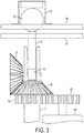
3 eine teilweise Vorderansicht einer Anordnung von kegelförmigen Radverzahnungen des verbesserten Rotator-/Verschiebemechanismus für Blätter bzw. Bögen zeigt, der in2 dargestellt ist.
-
1 Fig. 10 is a partial front view of a conventional sheet / sheet turning / translating mechanism for use in a finisher transport module; -
2 Fig. 10 is a partial perspective view of an improved sheet turning / translating mechanism according to the present disclosure; and -
3 FIG. 4 shows a partial front view of an array of tapered gear teeth of the improved sheet turning / shifting mechanism shown in FIG2 is shown.
Detaillierte BeschreibungDetailed description
Die Figuren dienen lediglich der Anschauung und sind nicht beschränkend auszulegen, wobei
Eine Mehrzahl herkömmlicher Finisher-Transportmodulsysteme verwendet einen Dreh- und Verschiebemechanismus für Medien, der zwei Scheiben/Walzen-Paare zum erneuten Ausrichten transportierter Blätter aus einer Zentrums- in eine Seitenausrichtung gebraucht. Jedoch ist die Spaltbreite zwischen der Scheibe und der Walze bezogen auf den Scheibendurchmesser klein/dünn, um Schlupf zu vermeiden. Der sich ergebende hohe Spaltdruck erzeugt jedoch eine Markierung beschichteter Medien. Entsprechend der vorliegenden Offenbarung wurde die bis dato zur Manipulation von Blättern in Zuführtransportmodulen verwendete Kombination aus einer Scheibe mit einem flachen Walzenspalt durch ein Paar von zylinderförmigen Antriebsrollen mit gegenläufigen kugelförmigen Walzen ersetzt.A variety of conventional finisher transport module systems utilize a media rotation and shifting mechanism that utilizes two pairs of disks / rollers to re-align transported sheets from center to side orientation. However, the gap width between the disc and the roller is small / thin relative to the disc diameter to avoid slippage. However, the resulting high nip pressure creates a mark on coated media. In accordance with the present disclosure, the combination of a flat nip disk previously used to manipulate sheets in feed transport modules has been replaced by a pair of cylindrical drive rollers with counter-rotating spherical rollers.
Wie in den
Wie insbesondere aus der
Es wird angemerkt, dass ein verbesserter Dreh-/Verschiebemechanismus zur Verwendung in einem Finisher-Transportmodulsystem offenbart wird, der eine Relativbewegung und einen hohen Druck auf einen Kontaktspalt durch Verwenden eines Zylinders und eines Kugelspalts vermeidet. Der Mechanismus verwendet eine Reihe von kegelförmigen Verzahnungen, beispielsweise Kegelverzahnung, wovon eines sich koaxial und unabhängig von den Antriebsrollenstangen dreht. Dadurch können die Antriebsrollen bezüglich ihrer eigenen Achse angetrieben werden, während gleichzeitig ein Drehen um die Drehachse der Stangen möglich ist. Über jeder Antriebsrolle ist eine Kugelwalze angeordnet, die die zur Führung eines Papiers in eine beliebige Richtung notwendige Normalkraft bereitstellt. Die Antriebsrollen werden vorteilhafterweise bezüglich ihres Zentrums angetrieben, während sie gleichzeitig und unabhängig um ihre vertikalen Achsen rotieren können. Unabhängige Antriebsgeschwindigkeiten ermöglichen ein Drehen von Papier, während ein Drehen um eine vertikale Achse ein Verschieben bzw. einen Versatz des Papiers ermöglicht. Folglich wird ein Verschieben, Vorrücken und Drehen von Blättern ohne Relativbewegung und ohne eine große Spaltoberfläche erreicht, wodurch ein Markieren von Medien verhindert wird.It is noted that an improved rotary / sliding mechanism for use in a finisher transport module system is disclosed that avoids relative movement and high pressure on a contact gap by using a cylinder and a ball gap. The mechanism uses a series of tapered gears, such as bevel gear, one of which rotates coaxially and independently of the drive roller rods. Thereby, the drive rollers can be driven with respect to their own axis, while at the same time a rotation about the axis of rotation of the rods is possible. Over each drive roller a ball roller is arranged, which provides the necessary for guiding a paper in any direction normal force. The drive rollers are advantageously driven with respect to their center while being able to simultaneously and independently rotate about their vertical axes. Independent drive speeds allow paper to rotate, while rotating about a vertical axis allows paper to shift or shift. Consequently, shifting, advancing and turning of blades without relative movement and without a large gap surface is achieved, thereby preventing marking of media.
Die Offenbarung umfasst eine verbesserte Dreh-/Versatzvorrichtung für Medien, die einen Zylinder auf einem Kugelspalt umfasst. Die Vorrichtung umfasst weiter eine Reihe von kegelförmigen Verzahnungen und/oder Stirnradverzahnungen, wobei eine davon bezüglich Antriebsrollenstangen koaxial ist und unabhängig rotiert. Dies ermöglicht ein Antreiben der Antriebsrollen um ihre eigene Achse, während gleichzeitig ein Drehen um die Achse der Rollenstangen möglich ist. Über einer jeden Antriebsrolle ist eine Kugelwalze vorgesehen. Diese stellt eine Normalkraft auf das Medium bereit. Folglich wird ein Verschieben, Vorrücken und Drehen von Blättern ohne Relativbewegung und ohne eine große Spaltoberfläche erreicht, wodurch ein Markieren von Medien verhindert wird.The disclosure includes an improved media media rotation / offset device that includes a cylinder on a ball nip. The apparatus further includes a series of tapered gears and / or spur gears, one of which is coaxial with respect to drive roller rods and independently rotates. This allows the drive rollers to be driven about their own axis while allowing rotation about the axis of the roller bars. Over each drive roller a ball roller is provided. This provides a normal force to the medium. Consequently, shifting, advancing and turning of blades without relative movement and without a large gap surface is achieved, thereby preventing marking of media.
Claims (3)
Applications Claiming Priority (2)
| Application Number | Priority Date | Filing Date | Title |
|---|---|---|---|
| US13/030,514 | 2011-02-18 | ||
| US13/030,514 US8348267B2 (en) | 2011-02-18 | 2011-02-18 | Media rotation and translation apparatus |
Publications (2)
| Publication Number | Publication Date |
|---|---|
| DE102012202477A1 DE102012202477A1 (en) | 2012-08-23 |
| DE102012202477B4 true DE102012202477B4 (en) | 2019-06-19 |
Family
ID=46605179
Family Applications (1)
| Application Number | Title | Priority Date | Filing Date |
|---|---|---|---|
| DE102012202477.8A Active DE102012202477B4 (en) | 2011-02-18 | 2012-02-17 | Media rotation and displacement device |
Country Status (3)
| Country | Link |
|---|---|
| US (1) | US8348267B2 (en) |
| JP (1) | JP5793091B2 (en) |
| DE (1) | DE102012202477B4 (en) |
Families Citing this family (5)
| Publication number | Priority date | Publication date | Assignee | Title |
|---|---|---|---|---|
| ITTO20120081A1 (en) * | 2012-02-01 | 2013-08-02 | Panini Spa | MOTORIZED DEVICE FOR ALIGNMENT AND FORWARDING FOR APPLIANCES FOR THE TREATMENT OF PAPER AND SIMILAR DOCUMENTS, IN PARTICULAR BANK CHECKS |
| KR101681503B1 (en) * | 2014-10-08 | 2016-12-01 | 노틸러스효성 주식회사 | Apparatus for automatical alignment and unit for adjusting skewness |
| US9233811B1 (en) * | 2015-01-16 | 2016-01-12 | Kabushiki Kaisha Toshiba | Image forming apparatus |
| DE102017105842B4 (en) * | 2017-03-17 | 2019-05-29 | Wincor Nixdorf International Gmbh | Device for aligning notes of value |
| CN111300847B (en) * | 2020-03-05 | 2020-12-01 | 苏州恒川光伏科技有限公司 | Pultrusion production line for polyurethane composite material |
Citations (6)
| Publication number | Priority date | Publication date | Assignee | Title |
|---|---|---|---|---|
| US2181241A (en) | 1937-07-06 | 1939-11-28 | Brehmer Maschinenfabrik Geb | Paper sheet feeding mechanism |
| DE1729652U (en) * | 1956-07-05 | 1956-09-13 | Georg Dr Ing Spiess | FEED DEVICE FOR SHEETS OF PAPER OD. DGL. ON THE BEND OR PROCESSING MACHINERY, IN PARTICULAR ON PRINTING MACHINES OF ALL KINDS. |
| DE1729625U (en) | 1955-06-03 | 1956-09-13 | Demag Ag | ROPE CONNECTION. |
| JPH05294500A (en) | 1992-04-17 | 1993-11-09 | Tokyo Electric Co Ltd | Paper conveyor |
| DE10013815A1 (en) | 1999-03-25 | 2000-09-28 | Fuji Photo Optical Co Ltd | Paper transport mechanism; has left and right transport rollers that can be inclined along paper with axes parallel to each other, and which rotate at identical speeds to transport paper |
| US6811152B2 (en) | 2001-12-21 | 2004-11-02 | C. P. Bourg S.A. | Method and device for controlling the orientation and alignment of individual sheets of paper passing on a conveyor |
Family Cites Families (8)
| Publication number | Priority date | Publication date | Assignee | Title |
|---|---|---|---|---|
| NL7612692A (en) * | 1976-11-16 | 1978-05-18 | Oce Van Der Grinten Nv | DEVICE FOR COPYING SHEET ORIGINALS. |
| US5280901A (en) * | 1993-03-24 | 1994-01-25 | Xerox Corporation | Sheet variable corrugating and feeding nip |
| US5402996A (en) * | 1994-02-16 | 1995-04-04 | Long; John A. | Apparatus and method for feeding cards from selected card stacks using a continuously rotating drive |
| DE19543774C2 (en) * | 1995-11-24 | 1999-04-15 | Heidelberger Druckmasch Ag | Device for the central adjustment of sheet guiding elements of a sheet-fed rotary printing machine |
| US5697609A (en) * | 1996-06-26 | 1997-12-16 | Xerox Corporation | Lateral sheet pre-registration device |
| US6053494A (en) * | 1997-08-04 | 2000-04-25 | Lexmark International, Inc. | Job offset assembly |
| JP4580602B2 (en) * | 2001-09-21 | 2010-11-17 | 株式会社東芝 | Paper sheet processing equipment |
| US6634521B1 (en) * | 2002-08-28 | 2003-10-21 | Xerox Corporation | Sheet registration and deskewing system with independent drives and steering |
-
2011
- 2011-02-18 US US13/030,514 patent/US8348267B2/en active Active
-
2012
- 2012-02-02 JP JP2012021319A patent/JP5793091B2/en not_active Expired - Fee Related
- 2012-02-17 DE DE102012202477.8A patent/DE102012202477B4/en active Active
Patent Citations (6)
| Publication number | Priority date | Publication date | Assignee | Title |
|---|---|---|---|---|
| US2181241A (en) | 1937-07-06 | 1939-11-28 | Brehmer Maschinenfabrik Geb | Paper sheet feeding mechanism |
| DE1729625U (en) | 1955-06-03 | 1956-09-13 | Demag Ag | ROPE CONNECTION. |
| DE1729652U (en) * | 1956-07-05 | 1956-09-13 | Georg Dr Ing Spiess | FEED DEVICE FOR SHEETS OF PAPER OD. DGL. ON THE BEND OR PROCESSING MACHINERY, IN PARTICULAR ON PRINTING MACHINES OF ALL KINDS. |
| JPH05294500A (en) | 1992-04-17 | 1993-11-09 | Tokyo Electric Co Ltd | Paper conveyor |
| DE10013815A1 (en) | 1999-03-25 | 2000-09-28 | Fuji Photo Optical Co Ltd | Paper transport mechanism; has left and right transport rollers that can be inclined along paper with axes parallel to each other, and which rotate at identical speeds to transport paper |
| US6811152B2 (en) | 2001-12-21 | 2004-11-02 | C. P. Bourg S.A. | Method and device for controlling the orientation and alignment of individual sheets of paper passing on a conveyor |
Also Published As
| Publication number | Publication date |
|---|---|
| DE102012202477A1 (en) | 2012-08-23 |
| JP2012171797A (en) | 2012-09-10 |
| US8348267B2 (en) | 2013-01-08 |
| JP5793091B2 (en) | 2015-10-14 |
| US20120211939A1 (en) | 2012-08-23 |
Similar Documents
| Publication | Publication Date | Title |
|---|---|---|
| DE102012202477B4 (en) | Media rotation and displacement device | |
| DE4104635B4 (en) | Device for rolling up web or strip-shaped materials | |
| DE69821414T2 (en) | Cutting and creasing machine with a device for longitudinal cutting | |
| DE2310552A1 (en) | DEVICE FOR MEASURING THE PROFILE OF TAPE MATERIAL | |
| DE2248683B2 (en) | Device for cross-cutting a continuously conveyed web of material | |
| EP2199240A1 (en) | Device for separating parts | |
| EP0970807A1 (en) | Roller having a variable diameter | |
| DE102006016410B3 (en) | Device for separating papers, plastic films and other thin-walled materials comprises a directly driven cutting roller, a counter roller and engaging rings and driven with the cutting roller by friction engagement with bearing rings | |
| DE102008048659A1 (en) | Apparatus and method for aligning sheets | |
| EP2079654B1 (en) | Pivotable positioning roller in the reversing winder | |
| DE102005010948B4 (en) | Device for separating a printed paper web | |
| EP3789330A1 (en) | Device and method for intermittently conveying a material sheet along a conveying direction and for cutting the material sheet | |
| EP2845825B1 (en) | Scoring device with rotatable transport device | |
| DE19856372A1 (en) | Conveyor with frame in which are cylindrical rollers | |
| DE19821603A1 (en) | Longitudinal folding device on the folder of rotary printing machines | |
| WO2009138067A1 (en) | Folding device comprising upstream or downstream blade shafts or comparable tool shafts | |
| DE1013664B (en) | Device for setting the positioning marks in a sheet processing machine, such as a printing machine and press for cutting paper or cardboard | |
| EP3578487B1 (en) | Printing machine with a transport device for transporting sheets to be printed | |
| DE1248599B (en) | Device for the radial adjustment of the rolls of rolling mills in a plane running parallel to the rolling direction | |
| DE102012205387B4 (en) | Magnetically coupled intermediate idler roller | |
| DE2112807C3 (en) | Device for printing or die-cutting of directly successive sections of a material web | |
| DE919711C (en) | Paper folding machine | |
| EP3459738A1 (en) | Device for processing a web or sheet shaped substrate | |
| DE3148667C1 (en) | Device for exchanging printing medium between zones offset from one another in the longitudinal direction of the roller in the inking unit of a rotary printing press | |
| EP2743072A1 (en) | Creasing method and apparatus |
Legal Events
| Date | Code | Title | Description |
|---|---|---|---|
| R012 | Request for examination validly filed | ||
| R082 | Change of representative |
Representative=s name: GRUENECKER, KINKELDEY, STOCKMAIR & SCHWANHAEUS, DE Representative=s name: GRUENECKER PATENT- UND RECHTSANWAELTE PARTG MB, DE |
|
| R012 | Request for examination validly filed |
Effective date: 20150216 |
|
| R016 | Response to examination communication | ||
| R018 | Grant decision by examination section/examining division | ||
| R020 | Patent grant now final |