JP5793091B2 - Processing transfer module and method for controlling orientation and arrangement of medium passing through processing transfer module - Google Patents
Processing transfer module and method for controlling orientation and arrangement of medium passing through processing transfer module Download PDFInfo
- Publication number
- JP5793091B2 JP5793091B2 JP2012021319A JP2012021319A JP5793091B2 JP 5793091 B2 JP5793091 B2 JP 5793091B2 JP 2012021319 A JP2012021319 A JP 2012021319A JP 2012021319 A JP2012021319 A JP 2012021319A JP 5793091 B2 JP5793091 B2 JP 5793091B2
- Authority
- JP
- Japan
- Prior art keywords
- transfer module
- bevel gear
- roll
- drive
- driven
- Prior art date
- Legal status (The legal status is an assumption and is not a legal conclusion. Google has not performed a legal analysis and makes no representation as to the accuracy of the status listed.)
- Expired - Fee Related
Links
- 238000012546 transfer Methods 0.000 title claims description 13
- 238000012545 processing Methods 0.000 title claims description 12
- 238000000034 method Methods 0.000 title claims description 5
- 238000003754 machining Methods 0.000 claims 2
- 230000033001 locomotion Effects 0.000 description 11
- 238000013404 process transfer Methods 0.000 description 2
- 230000005540 biological transmission Effects 0.000 description 1
- 238000012937 correction Methods 0.000 description 1
- 230000007423 decrease Effects 0.000 description 1
- 238000013461 design Methods 0.000 description 1
Images

Classifications
-
- B—PERFORMING OPERATIONS; TRANSPORTING
- B65—CONVEYING; PACKING; STORING; HANDLING THIN OR FILAMENTARY MATERIAL
- B65H—HANDLING THIN OR FILAMENTARY MATERIAL, e.g. SHEETS, WEBS, CABLES
- B65H5/00—Feeding articles separated from piles; Feeding articles to machines
- B65H5/06—Feeding articles separated from piles; Feeding articles to machines by rollers or balls, e.g. between rollers
- B65H5/062—Feeding articles separated from piles; Feeding articles to machines by rollers or balls, e.g. between rollers between rollers or balls
-
- B—PERFORMING OPERATIONS; TRANSPORTING
- B65—CONVEYING; PACKING; STORING; HANDLING THIN OR FILAMENTARY MATERIAL
- B65H—HANDLING THIN OR FILAMENTARY MATERIAL, e.g. SHEETS, WEBS, CABLES
- B65H9/00—Registering, e.g. orientating, articles; Devices therefor
- B65H9/16—Inclined tape, roller, or like article-forwarding side registers
- B65H9/166—Roller
-
- B—PERFORMING OPERATIONS; TRANSPORTING
- B65—CONVEYING; PACKING; STORING; HANDLING THIN OR FILAMENTARY MATERIAL
- B65H—HANDLING THIN OR FILAMENTARY MATERIAL, e.g. SHEETS, WEBS, CABLES
- B65H2403/00—Power transmission; Driving means
- B65H2403/40—Toothed gearings
- B65H2403/43—Bevel gearing
-
- B—PERFORMING OPERATIONS; TRANSPORTING
- B65—CONVEYING; PACKING; STORING; HANDLING THIN OR FILAMENTARY MATERIAL
- B65H—HANDLING THIN OR FILAMENTARY MATERIAL, e.g. SHEETS, WEBS, CABLES
- B65H2404/00—Parts for transporting or guiding the handled material
- B65H2404/60—Other elements in face contact with handled material
- B65H2404/69—Other means designated for special purpose
- B65H2404/696—Ball, sphere
- B65H2404/6961—Driving means
-
- B—PERFORMING OPERATIONS; TRANSPORTING
- B65—CONVEYING; PACKING; STORING; HANDLING THIN OR FILAMENTARY MATERIAL
- B65H—HANDLING THIN OR FILAMENTARY MATERIAL, e.g. SHEETS, WEBS, CABLES
- B65H2801/00—Application field
- B65H2801/24—Post -processing devices
- B65H2801/27—Devices located downstream of office-type machines
Landscapes
- Engineering & Computer Science (AREA)
- Mechanical Engineering (AREA)
- Delivering By Means Of Belts And Rollers (AREA)
- Registering Or Overturning Sheets (AREA)
- Folding Of Thin Sheet-Like Materials, Special Discharging Devices, And Others (AREA)
- Separation, Sorting, Adjustment, Or Bending Of Sheets To Be Conveyed (AREA)
Description
本開示は、広範には加工用移送モジュールシステムに関し、さらに詳細には、加工用移送モジュールを通過する媒体の向きおよび配置の制御に用いるための、改善された回転子移動器装置に関する。 The present disclosure relates generally to a processing transport module system, and more particularly to an improved rotor mover device for use in controlling the orientation and placement of media passing through the processing transport module.
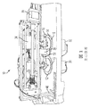
システムを通過するシートを回転および移動させるための加工移送モジュールシステムが知られていて、例えばアメリカ特許番号6,811,152が挙げられる。もう1つの例を、図1の従来技術において示され、加工移送モジュール10のシート回転子移動器機構が、各回転子ディスク12および14を別々に駆動する2つの回転子ディスクモータ30および32を含む。同じ方向に同じ速度で向きを変えるとき、シートは、通常の任意のニップセットのように(回転させずに、または、方向補正をせずに)回転子装置を通過する。モータを同じ方向および同じ速度で回転させ続けると、ステアリングアイドラ16および18をディスクの周りで回転させて、シートの中心部/外側寄りの位置を回転させずに修正することができる。このことは、スタッカのシートセットの量を補正し、下流に位置する加工装置の中心および端部の位置合わせを変更するには有益である。シートが所望の量に補正されたときを知るために、送りねじによって位置を決定できる端部センサ40がある。送りねじに接続されたモータ33は、センサ40を、1つのシートセットの中心部/外側寄りのセット距離に位置付け、次に、センサの位置を変えて、次のシートセットの中心部/外側寄りの位置を検出する。シートを回転させるために、モータが制御する回転子ディスクは、単に、異なる速度でスピンする。速度差が大きければ、媒体はより速く回転する。
Work transfer module systems for rotating and moving sheets passing through the system are known, such as US Pat. No. 6,811,152. Another example is shown in the prior art of FIG. 1, in which the sheet rotor mover mechanism of the
この設計の問題点は、ディスクが水平にスピンする一方で、アイドラが垂直にスピンすることである。(プロセスを横断する方向への)過度の相対運動を防止するために、各ディスクは、アイドラとの接触点に関して鋭い縁部を有している。図1の従来技術に高圧ニップを示す。高圧ニップは、ディスク12とアイドラ18との間に非常にわずかな接触点13を含み、ディスク14とアイドラ16との間に鋭い接触点15を含む。これにより、半径が基本的に1つであるが圧力が非常に高いために、相対運動は効果的に排除される。この高圧は、滑りの防止に必要であるが、結局のところ、ある媒体、特にコーティングを施したシートへのマーキングを引き起こしてしまう。
The problem with this design is that the disk spins horizontally while the idler spins vertically. In order to prevent excessive relative motion (in the direction across the process), each disk has a sharp edge with respect to the point of contact with the idler. A high pressure nip is shown in the prior art of FIG. The high pressure nip includes a very
それゆえに、ある種の媒体のマーキングを取り除く従来の加工移送モジュールシステムの過度の相対運動の問題を解決する必要が依然としてある。 Therefore, there remains a need to solve the problem of excessive relative motion of conventional process transfer module systems that remove certain media markings.
従って、上述の問題に答え、ここに開示するのは、球形ニップにおいて軸に取り付けられた駆動ロールの円筒を含む、改善された回転子/移動器装置である。一連の傘状歯車/平歯車が含まれ、それらのうちの1つは同軸上に、しかし、駆動ロールの軸に対して独立して回転する。これにより、駆動ロールを、それら自体の中心線に対して駆動でき、同時に、ロール軸の中心線に対して回転させることができる。ボールアイドラが、必要ないかなる方向にもシートを駆動するための必要な垂直力を有する各駆動ロール上に位置付けられる。従って、シート移動、突き揃え、および、回転が得られるが、それらは、相対運動を伴わず、より多くのニップ表面領域を有したものであり、これにより、いくらかの媒体のマーキングが取り除かれる。 Thus, in response to the above problems, disclosed herein is an improved rotor / mover device that includes a cylinder of a drive roll attached to a shaft at a spherical nip. A series of bevel / spur gears are included, one of which is coaxial but rotates independently with respect to the axis of the drive roll. Thereby, the drive rolls can be driven with respect to their own center line and at the same time can be rotated with respect to the center line of the roll axis. A ball idler is positioned on each drive roll that has the necessary vertical force to drive the seat in any required direction. Thus, sheet movement, alignment and rotation is obtained, but with no relative motion and with more nip surface area, which removes some media marking.
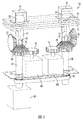
図面に関して言えば、これらの図面は、例示的な実施形態を示すために図示したものであり、限定を加えることを意図したものではない。図2は、媒体のマーキングを伴わない加工用移送モジュールシステムにおけるシートの回転および移動を成し遂げるための、本開示に従った改善されたシート回転子/移動器機構の部分透視図を示す。 Referring to the drawings, these drawings are shown to illustrate exemplary embodiments and are not intended to be limiting. FIG. 2 shows a partial perspective view of an improved sheet rotator / mover mechanism according to the present disclosure for accomplishing sheet rotation and movement in a processing transfer module system without media marking.
多くの従来の加工移送モジュールシステムは、中心の位置合わせから側面の位置合わせへと、搬送されたシートの位置合わせを再度行うための2対のディスク/アイドラを用いた、媒体の回転移動機構を使用している。しかし、ディスクとアイドラとの間のニップ幅が、ずれを回避するためにディスクの直径よりも薄く、それに起因する高いニップ圧力が、コーティングを施した媒体へのマーキングを引き起こしてしまう。本開示によって、フィーダ移送モジュールにおいてシートを動かすために従来用いられているディスクと平面アイドラニップとを組み合わせたものを、相対する球形のアイドラを備えた1対の円柱状の駆動ロールによって置き換えた。 Many conventional processing and transfer module systems employ a medium rotational movement mechanism that uses two pairs of discs / idlers to realign the conveyed sheet from center alignment to side alignment. I use it. However, the nip width between the disk and idler is thinner than the disk diameter to avoid misalignment, and the resulting high nip pressure causes marking on the coated media. According to the present disclosure, a combination of a disk and a planar idler nip conventionally used to move sheets in a feeder transport module is replaced by a pair of cylindrical drive rolls with opposing spherical idlers.
図2および図3に示すように、シート回転子/移動器機構50は、相対運動を取り除き、支持部材57および58との間を通過するシートと一体となって、容器55および56に収容された、相対する球形のアイドラ52および54と共にニップを形成する少なくとも2つの円柱状の駆動ロール51および53を含むことによって、高圧接触ニップの必要性を取り除く。ボールアイドラは、各駆動ロール上に位置付けられており、必要な垂直力を提供していかなる方向へもシートを駆動する。円柱状の駆動ロール51および53は、軸受け70および71を軸として旋回する回転可能な軸60および61上の垂直の中心線に対して、モータM1によって回転するために支持される。円柱状の駆動ロール51および53は、モータM2およびM3によって電力が供給される平歯車62および63を介して、中間駆動ロール80および81によって水平面において駆動される。
As shown in FIGS. 2 and 3, the seat rotator /
より具体的には、および、図3に見られるように、傘歯車/平歯車の組み合わせたもの66、68は、軸61に付着されているが、傘歯車66および平歯車68と軸61とは別々に回転できる。平歯車68および傘歯車66は、モータM2に接続された平歯車62によって駆動され、この動力伝達方向は、次に、傘歯車66と傘歯車67との円錐曲線の接触によって、90度角度を変更させられる。これにより、駆動ロール51が中間ロール80との接触圧力によって駆動される。傘歯車/平歯車(66、68)が駆動ロールの軸61と同軸上にあるので、駆動ロール51および軸61を、垂直の中心線に対して回転させることができ、一方、駆動ロールは、依然として、それ自体の中心線上で平歯車62によって駆動されている。駆動ロールの軸61が回転すると、それに応じて駆動ロール51の速度が上がるか、あるいは、下がり、従って、平歯車62に接続されたモータM2の速度は、それに応じて、ファームウェアコードによって調節される。
More specifically, and as seen in FIG. 3, the bevel gear /
相対運動を取り除いて球形ニップにおいて円筒を用いることによって高圧接触ニップの必要性を取り除く加工移送モジュールシステムに用いるための、改善された回転子/移動器機構を開示したことをここでは理解されたい。一連の傘状歯車が用いられ、それらのうちの1つは同軸上に回転するが、駆動ロールの軸に対して独立している。これにより、駆動ロールを、それら自体の中心線に対して駆動でき、同時に、ロール軸の中心線に対して回転させることができる。ボールアイドラは、各駆動ロール上に位置付けられており、垂直力を提供していかなる方向へもシートを駆動する。駆動ロールがそれらの中心に対して駆動され、一方、別々に、それらの垂直の中心線に対して同時に回転できることが有効である。有利には、独立した駆動ロールの速度によって、紙が回転できるようになり、一方、垂直の中心線の回転によって、紙が移動できるようになる。従って、シート移動、突き揃え、および、回転が得られるが、それらは、相対運動を伴わず、より多くのニップ表面領域を有したものであり、これにより、いくらかの媒体のマーキングが取り除かれる。 It should be understood herein that an improved rotor / mover mechanism has been disclosed for use in a process transfer module system that eliminates the need for a high pressure contact nip by removing relative motion and using a cylinder in a spherical nip. A series of bevel gears is used, one of which rotates coaxially but is independent of the axis of the drive roll. Thereby, the drive rolls can be driven with respect to their own center line and at the same time can be rotated with respect to the center line of the roll axis. A ball idler is positioned on each drive roll and provides normal force to drive the seat in any direction. It is advantageous for the drive rolls to be driven with respect to their center, while being separately rotatable simultaneously with respect to their vertical center line. Advantageously, the speed of the independent drive roll allows the paper to rotate, while the rotation of the vertical center line allows the paper to move. Thus, sheet movement, alignment and rotation is obtained, but with no relative motion and with more nip surface area, which removes some media marking.
Claims (4)
前記媒体が上を通過する一対の円柱状の駆動ロールであって、前記駆動ロールのそれぞれが中間ロールと接触して前記中間ロールによって駆動され、前記中間ロールのそれぞれが第1傘状歯車に接続されている、駆動ロールと、
前記駆動ロールのそれぞれを支持する軸と、
前記円柱状の駆動ロールのそれぞれと共にニップを形成する、球形のアイドラロールと、
前記円柱状の駆動ロールを水平面および垂直面において回転させるための前記軸に回転可能に接続されている第2傘状歯車および平歯車と、を含み、
前記第1傘状歯車は、前記軸のそれぞれに対して同軸上に位置付けられた前記第2傘状歯車によって駆動されるように接続され、
前記平歯車は、前記軸のそれぞれに対して同軸上に回転可能に取り付けられて前記第2傘状歯車に接続されている、加工用移送モジュール。 A machining transfer module including an improved rotor mover mechanism for use in controlling the orientation and placement of media passing through the machining transfer module, comprising:
A pair of cylindrical drive rolls through which the medium passes, each of the drive rolls being in contact with an intermediate roll and driven by the intermediate roll, and each of the intermediate rolls being connected to a first bevel gear A drive roll,
A shaft that supports each of the drive rolls;
A spherical idler roll that forms a nip with each of the cylindrical drive rolls;
Look including a second umbrella-shaped gear and the spur gear is rotatably coupled to the shaft for rotating in a horizontal plane and a vertical plane said cylindrical drive roll,
The first bevel gear is connected to be driven by the second bevel gear positioned coaxially to each of the shafts;
The spur gear is a processing transfer module that is coaxially rotatable with respect to each of the shafts and connected to the second bevel gear .
前記一対の駆動ロールをそれぞれ独立に水平面において回転駆動する2つのモータと、前記一対の駆動ロールを垂直面において回転駆動する1つのモータと、をさらに含む、加工用移送モジュール。 The processing transfer module according to claim 1,
A processing transfer module, further comprising: two motors that independently rotate the pair of drive rolls in a horizontal plane; and one motor that rotationally drives the pair of drive rolls in a vertical plane .
前記媒体が上を通過する、軸に備え付けられた一対の円柱状の駆動ロールであって、前記駆動ロールのそれぞれが中間ロールと接触して前記中間ロールによって駆動され、前記中間ロールのそれぞれが第1傘状歯車に接続されている、駆動ロールを準備するステップと、 A pair of cylindrical drive rolls mounted on a shaft through which the medium passes, each of the drive rolls being in contact with an intermediate roll and driven by the intermediate roll, each of the intermediate rolls being Providing a drive roll connected to one bevel gear;
前記駆動ロールと共にニップを形成する、球形のアイドラロールを準備するステップと、 Providing a spherical idler roll that forms a nip with the drive roll;
前記円柱状の駆動ロールを水平面および垂直面において回転させる前記軸に回転可能に接続されている第2傘状歯車および平歯車を準備するステップであって、前記第1傘状歯車は、前記軸のそれぞれに対して同軸上に位置付けられた前記第2傘状歯車によって駆動されるように接続され、前記平歯車は、前記軸のそれぞれに対して同軸上に回転可能に取り付けられて前記第2傘状歯車に接続されている、ステップと、を含む、方法。 Preparing a second bevel gear and a spur gear rotatably connected to the shaft for rotating the cylindrical drive roll in a horizontal plane and a vertical plane, wherein the first bevel gear is the shaft Are connected to be driven by the second bevel gear positioned coaxially with respect to each of the shafts, and the spur gear is rotatably mounted coaxially with respect to each of the shafts. A method connected to the bevel gear.
前記一対の駆動ロールは、それぞれ独立の2つのモータで水平面において回転駆動され、さらに別の1つのモータで垂直面において回転駆動される、方法。 The method of claim 3, wherein
The pair of drive rolls are driven to rotate in a horizontal plane by two independent motors, and are further driven to rotate in a vertical plane by another motor .
Applications Claiming Priority (2)
| Application Number | Priority Date | Filing Date | Title |
|---|---|---|---|
| US13/030,514 US8348267B2 (en) | 2011-02-18 | 2011-02-18 | Media rotation and translation apparatus |
| US13/030,514 | 2011-02-18 |
Publications (3)
| Publication Number | Publication Date |
|---|---|
| JP2012171797A JP2012171797A (en) | 2012-09-10 |
| JP2012171797A5 JP2012171797A5 (en) | 2015-03-05 |
| JP5793091B2 true JP5793091B2 (en) | 2015-10-14 |
Family
ID=46605179
Family Applications (1)
| Application Number | Title | Priority Date | Filing Date |
|---|---|---|---|
| JP2012021319A Expired - Fee Related JP5793091B2 (en) | 2011-02-18 | 2012-02-02 | Processing transfer module and method for controlling orientation and arrangement of medium passing through processing transfer module |
Country Status (3)
| Country | Link |
|---|---|
| US (1) | US8348267B2 (en) |
| JP (1) | JP5793091B2 (en) |
| DE (1) | DE102012202477B4 (en) |
Families Citing this family (7)
| Publication number | Priority date | Publication date | Assignee | Title |
|---|---|---|---|---|
| ITTO20120081A1 (en) * | 2012-02-01 | 2013-08-02 | Panini Spa | MOTORIZED DEVICE FOR ALIGNMENT AND FORWARDING FOR APPLIANCES FOR THE TREATMENT OF PAPER AND SIMILAR DOCUMENTS, IN PARTICULAR BANK CHECKS |
| KR101681503B1 (en) * | 2014-10-08 | 2016-12-01 | 노틸러스효성 주식회사 | Apparatus for automatical alignment and unit for adjusting skewness |
| US9233811B1 (en) * | 2015-01-16 | 2016-01-12 | Kabushiki Kaisha Toshiba | Image forming apparatus |
| DE102017105842B4 (en) * | 2017-03-17 | 2019-05-29 | Wincor Nixdorf International Gmbh | Device for aligning notes of value |
| CN111300847B (en) * | 2020-03-05 | 2020-12-01 | 苏州恒川光伏科技有限公司 | Pultrusion production line for polyurethane composite material |
| WO2021181567A1 (en) * | 2020-03-11 | 2021-09-16 | 富士通フロンテック株式会社 | Centering mechanism and paper-sheet handling device |
| JP2025026174A (en) * | 2023-08-10 | 2025-02-21 | キヤノン株式会社 | SHEET CONVEYING APPARATUS, IMAGE FORMING APPARATUS, AND IMAGE FORMING SYSTEM |
Family Cites Families (14)
| Publication number | Priority date | Publication date | Assignee | Title |
|---|---|---|---|---|
| US2181241A (en) | 1937-07-06 | 1939-11-28 | Brehmer Maschinenfabrik Geb | Paper sheet feeding mechanism |
| DE1729625U (en) | 1955-06-03 | 1956-09-13 | Demag Ag | ROPE CONNECTION. |
| DE1729652U (en) * | 1956-07-05 | 1956-09-13 | Georg Dr Ing Spiess | FEED DEVICE FOR SHEETS OF PAPER OD. DGL. ON THE BEND OR PROCESSING MACHINERY, IN PARTICULAR ON PRINTING MACHINES OF ALL KINDS. |
| NL7612692A (en) * | 1976-11-16 | 1978-05-18 | Oce Van Der Grinten Nv | DEVICE FOR COPYING SHEET ORIGINALS. |
| JPH05294500A (en) | 1992-04-17 | 1993-11-09 | Tokyo Electric Co Ltd | Paper transport device |
| US5280901A (en) * | 1993-03-24 | 1994-01-25 | Xerox Corporation | Sheet variable corrugating and feeding nip |
| US5402996A (en) * | 1994-02-16 | 1995-04-04 | Long; John A. | Apparatus and method for feeding cards from selected card stacks using a continuously rotating drive |
| DE19543774C2 (en) * | 1995-11-24 | 1999-04-15 | Heidelberger Druckmasch Ag | Device for the central adjustment of sheet guiding elements of a sheet-fed rotary printing machine |
| US5697609A (en) * | 1996-06-26 | 1997-12-16 | Xerox Corporation | Lateral sheet pre-registration device |
| US6053494A (en) * | 1997-08-04 | 2000-04-25 | Lexmark International, Inc. | Job offset assembly |
| JP2000272775A (en) | 1999-03-25 | 2000-10-03 | Fuji Photo Optical Co Ltd | Paper carrying mechanism |
| JP4580602B2 (en) * | 2001-09-21 | 2010-11-17 | 株式会社東芝 | Paper sheet processing equipment |
| DE02028159T1 (en) | 2001-12-21 | 2004-04-15 | C.P. Bourg S.A. | Method and device for controlling the orientation and alignment of individual sheets of paper passing on a conveyor belt |
| US6634521B1 (en) * | 2002-08-28 | 2003-10-21 | Xerox Corporation | Sheet registration and deskewing system with independent drives and steering |
-
2011
- 2011-02-18 US US13/030,514 patent/US8348267B2/en not_active Expired - Fee Related
-
2012
- 2012-02-02 JP JP2012021319A patent/JP5793091B2/en not_active Expired - Fee Related
- 2012-02-17 DE DE102012202477.8A patent/DE102012202477B4/en not_active Expired - Fee Related
Also Published As
| Publication number | Publication date |
|---|---|
| JP2012171797A (en) | 2012-09-10 |
| DE102012202477B4 (en) | 2019-06-19 |
| US8348267B2 (en) | 2013-01-08 |
| DE102012202477A1 (en) | 2012-08-23 |
| US20120211939A1 (en) | 2012-08-23 |
Similar Documents
| Publication | Publication Date | Title |
|---|---|---|
| JP5793091B2 (en) | Processing transfer module and method for controlling orientation and arrangement of medium passing through processing transfer module | |
| CN102753848B (en) | Anti-drift turning roll system | |
| JP2006289914A5 (en) | ||
| TWI446974B (en) | And a conveyor device for coating the substrate on both sides | |
| JPH0839480A (en) | Method and device for transversely cutting an object to be cut | |
| CN102164834B (en) | Device and method for the alignment of sheets | |
| CN110002201A (en) | A kind of sterile paper box conveying device | |
| CN206203323U (en) | Fruit feed arrangement | |
| JP5800723B2 (en) | Medium rotational movement mechanism | |
| CN102559954A (en) | Automatic oil edge machine | |
| CN104608464A (en) | Angle-adjustable arc flattening roll | |
| US8424873B2 (en) | Magnetic coupled intermediate idler | |
| CN207174820U (en) | A kind of positioner to sort | |
| CN223877693U (en) | Online overprinting adjusting device of version roller | |
| JP6146652B2 (en) | Web spacing adjustment mechanism | |
| CN105619890A (en) | Structure for adjusting preheating range through double rocker arms of corrugating machine | |
| CN218490021U (en) | Aluminum foil paper deviation correcting device of cigarette packet packing machine | |
| JPS5847299B2 (en) | Flexible feeding device for long materials with circular cross section | |
| JP2012171796A5 (en) | ||
| CN106743310B (en) | Belt conveyor automatic centre regulating lower roller group | |
| JP2012017182A (en) | Meandering correction device | |
| CN119526882A (en) | A device for adjusting the plate roller on-line overprinting | |
| CN105173566B (en) | A kind of synchronous spin mechanics of rotary body | |
| JP6065310B2 (en) | Conveying device, production system, and conveying method | |
| JP2020033190A5 (en) |
Legal Events
| Date | Code | Title | Description |
|---|---|---|---|
| RD04 | Notification of resignation of power of attorney |
Free format text: JAPANESE INTERMEDIATE CODE: A7424 Effective date: 20130826 |
|
| A521 | Request for written amendment filed |
Free format text: JAPANESE INTERMEDIATE CODE: A523 Effective date: 20150120 |
|
| A621 | Written request for application examination |
Free format text: JAPANESE INTERMEDIATE CODE: A621 Effective date: 20150120 |
|
| A871 | Explanation of circumstances concerning accelerated examination |
Free format text: JAPANESE INTERMEDIATE CODE: A871 Effective date: 20150120 |
|
| A975 | Report on accelerated examination |
Free format text: JAPANESE INTERMEDIATE CODE: A971005 Effective date: 20150210 |
|
| A131 | Notification of reasons for refusal |
Free format text: JAPANESE INTERMEDIATE CODE: A131 Effective date: 20150317 |
|
| A521 | Request for written amendment filed |
Free format text: JAPANESE INTERMEDIATE CODE: A523 Effective date: 20150601 |
|
| TRDD | Decision of grant or rejection written | ||
| A01 | Written decision to grant a patent or to grant a registration (utility model) |
Free format text: JAPANESE INTERMEDIATE CODE: A01 Effective date: 20150714 |
|
| A61 | First payment of annual fees (during grant procedure) |
Free format text: JAPANESE INTERMEDIATE CODE: A61 Effective date: 20150807 |
|
| R150 | Certificate of patent or registration of utility model |
Ref document number: 5793091 Country of ref document: JP Free format text: JAPANESE INTERMEDIATE CODE: R150 |
|
| R250 | Receipt of annual fees |
Free format text: JAPANESE INTERMEDIATE CODE: R250 |
|
| R250 | Receipt of annual fees |
Free format text: JAPANESE INTERMEDIATE CODE: R250 |
|
| R250 | Receipt of annual fees |
Free format text: JAPANESE INTERMEDIATE CODE: R250 |
|
| LAPS | Cancellation because of no payment of annual fees |