DE102012111473A1 - Workpiece holding device - Google Patents
Workpiece holding device Download PDFInfo
- Publication number
- DE102012111473A1 DE102012111473A1 DE102012111473.0A DE102012111473A DE102012111473A1 DE 102012111473 A1 DE102012111473 A1 DE 102012111473A1 DE 102012111473 A DE102012111473 A DE 102012111473A DE 102012111473 A1 DE102012111473 A1 DE 102012111473A1
- Authority
- DE
- Germany
- Prior art keywords
- clamping piece
- piece part
- workpiece
- clamping
- holding device
- Prior art date
- Legal status (The legal status is an assumption and is not a legal conclusion. Google has not performed a legal analysis and makes no representation as to the accuracy of the status listed.)
- Withdrawn
Links
- 239000012530 fluid Substances 0.000 claims description 24
- 230000005484 gravity Effects 0.000 claims description 9
- 230000002093 peripheral effect Effects 0.000 claims description 7
- 230000000149 penetrating effect Effects 0.000 claims description 2
- 239000011248 coating agent Substances 0.000 claims 1
- 238000000576 coating method Methods 0.000 claims 1
- 238000003754 machining Methods 0.000 description 4
- 238000003801 milling Methods 0.000 description 4
- BUHVIAUBTBOHAG-FOYDDCNASA-N (2r,3r,4s,5r)-2-[6-[[2-(3,5-dimethoxyphenyl)-2-(2-methylphenyl)ethyl]amino]purin-9-yl]-5-(hydroxymethyl)oxolane-3,4-diol Chemical compound COC1=CC(OC)=CC(C(CNC=2C=3N=CN(C=3N=CN=2)[C@H]2[C@@H]([C@H](O)[C@@H](CO)O2)O)C=2C(=CC=CC=2)C)=C1 BUHVIAUBTBOHAG-FOYDDCNASA-N 0.000 description 1
- 230000015572 biosynthetic process Effects 0.000 description 1
- 230000005489 elastic deformation Effects 0.000 description 1
- 230000000977 initiatory effect Effects 0.000 description 1
- 239000007788 liquid Substances 0.000 description 1
- 238000000034 method Methods 0.000 description 1
Images


Classifications
-
- B—PERFORMING OPERATIONS; TRANSPORTING
- B23—MACHINE TOOLS; METAL-WORKING NOT OTHERWISE PROVIDED FOR
- B23Q—DETAILS, COMPONENTS, OR ACCESSORIES FOR MACHINE TOOLS, e.g. ARRANGEMENTS FOR COPYING OR CONTROLLING; MACHINE TOOLS IN GENERAL CHARACTERISED BY THE CONSTRUCTION OF PARTICULAR DETAILS OR COMPONENTS; COMBINATIONS OR ASSOCIATIONS OF METAL-WORKING MACHINES, NOT DIRECTED TO A PARTICULAR RESULT
- B23Q16/00—Equipment for precise positioning of tool or work into particular locations not otherwise provided for
- B23Q16/02—Indexing equipment
- B23Q16/04—Indexing equipment having intermediate members, e.g. pawls, for locking the relatively movable parts in the indexed position
- B23Q16/06—Rotary indexing
- B23Q16/065—Rotary indexing with a continuous drive
-
- B—PERFORMING OPERATIONS; TRANSPORTING
- B23—MACHINE TOOLS; METAL-WORKING NOT OTHERWISE PROVIDED FOR
- B23Q—DETAILS, COMPONENTS, OR ACCESSORIES FOR MACHINE TOOLS, e.g. ARRANGEMENTS FOR COPYING OR CONTROLLING; MACHINE TOOLS IN GENERAL CHARACTERISED BY THE CONSTRUCTION OF PARTICULAR DETAILS OR COMPONENTS; COMBINATIONS OR ASSOCIATIONS OF METAL-WORKING MACHINES, NOT DIRECTED TO A PARTICULAR RESULT
- B23Q16/00—Equipment for precise positioning of tool or work into particular locations not otherwise provided for
- B23Q16/02—Indexing equipment
- B23Q16/04—Indexing equipment having intermediate members, e.g. pawls, for locking the relatively movable parts in the indexed position
- B23Q16/06—Rotary indexing
-
- B—PERFORMING OPERATIONS; TRANSPORTING
- B23—MACHINE TOOLS; METAL-WORKING NOT OTHERWISE PROVIDED FOR
- B23Q—DETAILS, COMPONENTS, OR ACCESSORIES FOR MACHINE TOOLS, e.g. ARRANGEMENTS FOR COPYING OR CONTROLLING; MACHINE TOOLS IN GENERAL CHARACTERISED BY THE CONSTRUCTION OF PARTICULAR DETAILS OR COMPONENTS; COMBINATIONS OR ASSOCIATIONS OF METAL-WORKING MACHINES, NOT DIRECTED TO A PARTICULAR RESULT
- B23Q3/00—Devices holding, supporting, or positioning work or tools, of a kind normally removable from the machine
- B23Q3/02—Devices holding, supporting, or positioning work or tools, of a kind normally removable from the machine for mounting on a work-table, tool-slide, or analogous part
- B23Q3/06—Work-clamping means
- B23Q3/066—Bench vices
-
- B—PERFORMING OPERATIONS; TRANSPORTING
- B25—HAND TOOLS; PORTABLE POWER-DRIVEN TOOLS; MANIPULATORS
- B25B—TOOLS OR BENCH DEVICES NOT OTHERWISE PROVIDED FOR, FOR FASTENING, CONNECTING, DISENGAGING OR HOLDING
- B25B1/00—Vices
- B25B1/06—Arrangements for positively actuating jaws
- B25B1/10—Arrangements for positively actuating jaws using screws
- B25B1/103—Arrangements for positively actuating jaws using screws with one screw perpendicular to the jaw faces, e.g. a differential or telescopic screw
-
- B—PERFORMING OPERATIONS; TRANSPORTING
- B25—HAND TOOLS; PORTABLE POWER-DRIVEN TOOLS; MANIPULATORS
- B25B—TOOLS OR BENCH DEVICES NOT OTHERWISE PROVIDED FOR, FOR FASTENING, CONNECTING, DISENGAGING OR HOLDING
- B25B1/00—Vices
- B25B1/06—Arrangements for positively actuating jaws
- B25B1/10—Arrangements for positively actuating jaws using screws
- B25B1/106—Arrangements for positively actuating jaws using screws with mechanical or hydraulic power amplifiers
-
- B—PERFORMING OPERATIONS; TRANSPORTING
- B25—HAND TOOLS; PORTABLE POWER-DRIVEN TOOLS; MANIPULATORS
- B25B—TOOLS OR BENCH DEVICES NOT OTHERWISE PROVIDED FOR, FOR FASTENING, CONNECTING, DISENGAGING OR HOLDING
- B25B1/00—Vices
- B25B1/22—Arrangements for turning or tilting vices
-
- B—PERFORMING OPERATIONS; TRANSPORTING
- B25—HAND TOOLS; PORTABLE POWER-DRIVEN TOOLS; MANIPULATORS
- B25B—TOOLS OR BENCH DEVICES NOT OTHERWISE PROVIDED FOR, FOR FASTENING, CONNECTING, DISENGAGING OR HOLDING
- B25B1/00—Vices
- B25B1/24—Details, e.g. jaws of special shape, slideways
- B25B1/2405—Construction of the jaws
- B25B1/241—Construction of the jaws characterised by surface features or material
- B25B1/2415—Construction of the jaws characterised by surface features or material being composed of a plurality of parts adapting to the shape of the workpiece
-
- B—PERFORMING OPERATIONS; TRANSPORTING
- B25—HAND TOOLS; PORTABLE POWER-DRIVEN TOOLS; MANIPULATORS
- B25B—TOOLS OR BENCH DEVICES NOT OTHERWISE PROVIDED FOR, FOR FASTENING, CONNECTING, DISENGAGING OR HOLDING
- B25B1/00—Vices
- B25B1/24—Details, e.g. jaws of special shape, slideways
- B25B1/2405—Construction of the jaws
- B25B1/2431—Construction of the jaws the whole jaw being pivotable around an axis perpendicular to the actioning direction of the vice
Landscapes
- Engineering & Computer Science (AREA)
- Mechanical Engineering (AREA)
- Jigs For Machine Tools (AREA)
Abstract
Die vorliegende Erfindung betrifft eine Werkstückhaltevorrichtung für mehrseitig zu bearbeitende Werkstücke, wobei das Werkstück zwischen einer mit zumindest einer Stützspindel der Werkstückhaltevorrichtung in Wirkverbindung stehenden und um eine erste Achse drehbaren ersten Werkstückhalterung und zumindest einer mit zumindest einer Antriebsspindel der Werkstückhaltevorrichtung in Wirkverbindung stehenden und um die erste Achse drehbaren zweiten Werkstückhalterung bezüglich der ersten Achse axial, radial und durch Kraftschluss mittels einer zwischen der ersten Werkstückhalterung und der zweiten Werkstückhalterung in axialer Richtung der ersten Achse schraubstockartig aufbaubaren und auf gegenüberliegende Seiten des Werkstücks wirkenden Klemmkraft haltbar ist, wobei die erste Werkstückhalterung zumindest ein erstes Klemmstück mit einer der zweiten Werkstückhalterung und/oder dem Werkstück zugewandten ersten ebenen Klemmfläche und die zweite Werkstückhalterung zumindest ein zweites Klemmstück mit einer der ersten Werkstückhalterung und/oder dem Werkstück zugewandten zweiten ebenen Klemmfläche aufweist bzw. aufweisen, wobei ferner das erste Klemmstück und/oder das zweite Klemmstück zweiteilig aufgebaut ist bzw. sind, wobei ein erstes Klemmstückteil des jeweiligen Klemmstücks derartig relativ zu dem zweiten Klemmstückteil des Klemmstücks bewegbar ist, dass ein erster Winkel zwischen der ersten Achse und der Normalenrichtung der ersten Klemmfläche und/oder ein zweiter Winkel zwischen der ersten Achse und der Normalenrichtung der zweiten Klemmfläche veränderbar ist.The present invention relates to a workpiece holding device for workpieces to be machined on several sides, the workpiece being between a first workpiece holder that is operatively connected to at least one support spindle of the workpiece holding device and rotatable about a first axis and at least one that is operatively connected to at least one drive spindle of the workpiece holding device and around the first Axis rotatable second workpiece holder with respect to the first axis axially, radially and by friction by means of a vice-like build-up between the first workpiece holder and the second workpiece holder in the axial direction of the first axis and acting on opposite sides of the workpiece, the first workpiece holder being at least a first Clamping piece with one of the second workpiece holder and / or the first flat clamping surface facing the workpiece and the second workpiece holder st has or have a second clamping piece with one of the first workpiece holder and / or the second flat clamping surface facing the workpiece, wherein furthermore the first clamping piece and / or the second clamping piece is or are constructed in two parts, a first clamping piece part of the respective clamping piece being relative in this way is movable to the second clamping piece part of the clamping piece that a first angle between the first axis and the normal direction of the first clamping surface and / or a second angle between the first axis and the normal direction of the second clamping surface can be changed.
Description
Die vorliegende Erfindung betrifft eine Werkstückhaltevorrichtung für mehrseitig zu bearbeitende Werkstücke, wobei das Werkstück zwischen einer mit zumindest einer Stützspindel der Werkstückhaltevorrichtung in Wirkverbindung stehenden und um eine erste Achse drehbaren ersten Werkstückhalterung und zumindest einer mit zumindest einer Antriebsspindel der Werkstückhaltevorrichtung in Wirkverbindung stehenden und um die erste Achse drehbaren zweiten Werkstückhalterung bezüglich der ersten Achse axial, radial und durch Kraftschluss mittels einer zwischen der ersten Werkstückhalterung und der zweiten Werkstückhalterung in axialer Richtung der ersten Achse schraubstockartig aufbaubaren und auf gegenüberliegende Seiten des Werkstücks wirkenden Klemmkraft haltbar ist, wobei die erste Werkstückhalterung zumindest ein erstes Klemmstück mit einer der zweiten Werkstückhalterung und/oder dem Werkstück zugewandten ersten ebenen Klemmfläche und die zweite Werkstückhalterung zumindest ein zweites Klemmstück mit einer der ersten Werkstückhalterung und/oder dem Werkstück zugewandten zweiten ebenen Klemmfläche aufweist bzw. aufweisen. The present invention relates to a workpiece holding device for workpieces to be machined on several sides, wherein the workpiece between a first workpiece holder operatively connected to at least one support spindle of the workpiece holding device and rotatable about a first axis and at least one operatively connected to at least one drive spindle of the workpiece holding device and the first Axially rotatable second workpiece holder with respect to the first axis axially, radially and by frictional connection by means of a schraubstockartig between the first workpiece holder and the second workpiece holder in the axial direction of the first axis aufbaubar and acting on opposite sides of the workpiece clamping force is durable, wherein the first workpiece holder at least a first Clamping piece with one of the second workpiece holder and / or the workpiece facing first flat clamping surface and the second workpiece holder lower a second clamping piece with one of the first workpiece holder and / or the workpiece facing second flat clamping surface has or have.
Werkstückhaltevorrichtungen sind aus dem Stand der Technik grundsätzlich bekannt. So offenbart beispielsweise die
Eine gattungsgemäße Werkstückhaltevorrichtung ist darüber hinaus aus der
Darüber hinaus offenbart die
Die aus dem Stand der Technik bekannten Werkstückhaltevorrichtungen haben sich grundsätzlich bewährt. The known from the prior art workpiece holding devices have basically proven.
In den
Die Werkstückhaltevorrichtung umfasst ein erstes Gehäuse
Um eine mehrseitige Bearbeitung des Werkstücks
In der in
In
Aufgrund der Tatsache, dass das Klemmstück
Sowohl die mögliche Relativbewegung des Werkstücks
Es ist daher Aufgabe der vorliegenden Erfindung die gattungsgemäße Werkstückhaltevorrichtung derartig weiterzuentwickeln, dass die Nachteile des Stands der Technik überwunden werden, insbesondere eine Werkstückhaltevorrichtung bereitgestellt wird, bei welcher eine präzise Bearbeitung eines Werkstücks in weiten Toleranzbereichen bezüglich der Form des Werkstücks ermöglicht wird, insbesondere eine Bewegung des Werkstücks in eine radiale Richtung einer ersten Achse einer Antriebsspindel und/oder eine Verformung des Werkstücks vermieden wird. It is therefore an object of the present invention further develop the generic workpiece holding device such that the disadvantages of the prior art are overcome, in particular a workpiece holding device is provided, in which a precise machining of a workpiece in wide tolerance ranges with respect to the shape of the workpiece is made possible, in particular a movement of the workpiece in a radial direction of a first axis of a drive spindle and / or deformation of the workpiece is avoided.
Diese Aufgabe wird erfindungsgemäß dadurch gelöst, dass das erste Klemmstück und/oder das zweite Klemmstück zweiteilig aufgebaut ist bzw. sind, wobei ein erstes Klemmstückteil des jeweiligen Klemmstücks derartig relativ zu dem zweiten Klemmstückteil des Klemmstücks bewegbar ist, dass ein erster Winkel zwischen der ersten Achse und der Normalenrichtung der ersten Klemmfläche und/oder ein zweiter Winkel zwischen der ersten Achse und der Normalenrichtung der zweiten Klemmfläche veränderbar ist. This object is achieved in that the first clamping piece and / or the second clamping piece is constructed in two parts, wherein a first clamping piece part of the respective clamping piece is such relatively movable to the second clamping piece part of the clamping piece, that a first angle between the first axis and the normal direction of the first clamping surface and / or a second angle between the first axis and the normal direction of the second clamping surface is variable.
Dabei ist besonders bevorzugt, dass die Stützspindel in zumindest einem ersten Gehäuse gelagert ist und/oder die Stützspindel und/oder das erste Gehäuse, vorzugsweise mittels zumindest einer Antriebseinrichtung, in koaxialer Richtung der ersten Achse und/oder der Antriebsspindel verschiebbar, vorzugsweise hin- und herbewegbar, gelagert ist und/oder die Antriebsspindel in zumindest einem zweiten Gehäuse gelagert ist und/oder die Antriebsspindel zumindest eine, insbesondere um die erste Achse, winkelschaltbare Winkelschalteinrichtung umfasst. It is particularly preferred that the support spindle is mounted in at least a first housing and / or the support spindle and / or the first housing, preferably by means of at least one drive means in the coaxial direction of the first axis and / or the drive spindle displaceable, preferably back and can be moved, stored and / or the drive spindle is mounted in at least one second housing and / or the drive spindle comprises at least one, in particular about the first axis, angularly switchable angle switching device.
Weiterhin wird bei der vorgenannten Ausführungsform vorgeschlagen, dass das erste Gehäuse und das zweite Gehäuse an zumindest einer Tragstruktur, wie einem Maschinengestell, gelagert sind. Furthermore, in the aforementioned embodiment, it is proposed that the first housing and the second housing are mounted on at least one support structure, such as a machine frame.
Eine erfindungsgemäße Werkstückhaltevorrichtung kann auch dadurch gekennzeichnet sein, dass die Winkelschalteinrichtung und/oder die Antriebseinrichtung zumindest einen motorischen, elektromotorischen, hydraulischen und/oder pneumatischen Aktuator umfasst. A workpiece holding device according to the invention can also be characterized in that the angle switching device and / or the drive device comprises at least one motor, electromotive, hydraulic and / or pneumatic actuator.
Die Erfindung schlägt auf, dass die durch die erste Werkstückhalterung und die zweite Werkstückhalterung aufgebaute Klemmkraft im wesentlichen ausschließlich kraftschlüssig wirkt. The invention proposes that the clamping force built up by the first workpiece holder and the second workpiece holder acts essentially exclusively in a force-locking manner.
Weiterhin ist bevorzugt, dass die erste Klemmfläche und/oder die zweite Klemmfläche auf der dem ersten Klemmstückteil abgewandten Oberfläche des zweiten Klemmstückteils angeordnet ist bzw. sind und/oder im Bereich der ersten Klemmfläche und/oder im Bereich der zweiten Klemmfläche eine einen Reibungswiderstand erhöhende Struktur, wie eine Riffelung und/oder einen Belag vorhanden ist.. It is further preferred that the first clamping surface and / or the second clamping surface is arranged on the surface of the second clamping piece part facing away from the first clamping piece part and / or in the region of the first clamping surface and / or in the region of the second clamping surface a structure increasing a frictional resistance how a corrugation and / or a covering is present ..
Besonders bevorzugt ist, dass das erste Klemmstückteil und das zweite Klemmstückteil über zumindest ein Gelenklager, vorzugsweise verliersicher und/oder drehmitnahmesicher, miteinander verbunden sind. It is particularly preferred that the first clamping piece part and the second clamping piece part are connected to each other via at least one hinge bearing, preferably captive and / or torque-proof.
Weiterhin kann eine erfindungsgemäße Werkstückhaltevorrichtung dadurch gekennzeichnet sein, dass das erste Klemmstückteil im Bereich zumindest einer ersten Kontaktfläche mit zumindest einer zweiten Kontaktfläche des zweiten Klemmstückteils in Kontakt steht, wobei die erste Achse durch einen Schwerpunkt der ersten Kontaktfläche, insbesondere einer Projektion der ersten Kontaktfläche in eine Ebene senkrecht zu der ersten Achse, und/oder einen Schwerpunkt der zweiten Kontaktfläche, insbesondere einer Projektion der zweiten Kontaktfläche in eine Ebene senkrecht zu der ersten Achse, verläuft. Furthermore, a workpiece holding device according to the invention can be characterized in that the first clamping piece part is in contact with at least one first contact surface of at least one second contact surface of the second clamping piece part, wherein the first axis by a center of gravity of the first contact surface, in particular a projection of the first contact surface in a Plane perpendicular to the first axis, and / or a center of gravity of the second contact surface, in particular a projection of the second contact surface in a plane perpendicular to the first axis extends.
Bei der vorgenannten Ausführungsform ist besonders bevorzugt, dass die erste Kontaktfläche kleiner als eine dem zweiten Klemmstückteil zugewandte erste Oberfläche des ersten Klemmstückteils und/oder die zweite Kontaktfläche kleiner als eine dem ersten Klemmstückteil zugewandte zweite Oberfläche des zweiten Klemmstückteils ist bzw. sind, wobei vorzugsweise die Fläche der ersten Oberfläche mehr als 125% der Fläche der ersten Kontaktfläche beträgt und/oder die Fläche der zweiten Oberfläche mehr als 125% der Fläche der zweiten Kontaktfläche beträgt, und/oder die erste Kontaktfläche zumindest bereichsweise von der ersten Oberfläche vorsteht und/oder die zweite Kontaktfläche zumindest bereichsweise von der zweiten Oberfläche vorsteht. In the aforementioned embodiment, it is particularly preferred that the first contact surface is smaller than a first surface of the first clamping piece part facing the second clamping piece part and / or the second contact surface is smaller than a second surface of the second clamping piece part facing the first clamping piece part Area of the first surface is more than 125% of the area of the first contact surface and / or the surface of the second surface is more than 125% of the area of the second contact area, and / or the first contact area at least partially from the first surface projecting and / or the second contact surface protrudes at least partially from the second surface.
Die beiden vorgenannten Ausführungsformen können auch dadurch gekennzeichnet sein, dass die erste Kontaktfläche und/oder die zweite Kontaktfläche zumindest bereichsweise senkrecht zu der ersten Achse verläuft, zumindest bereichsweise in einer durch die erste Achse und eine Senkrechte zu der ersten Achse aufgespannten Ebene eine gewölbte Kontur aufweist und/oder geneigt verläuft. The two aforementioned embodiments can also be characterized in that the first contact surface and / or the second contact surface extends at least partially perpendicular to the first axis, at least partially in a plane defined by the first axis and a perpendicular plane to the first axis has a curved contour and / or inclined.
Weiterhin wird für die vorgenannten Ausführungsformen vorgeschlagen, dass die erste Kontaktfläche und/oder die zweite Kontaktfläche in einer Ebene senkrecht zu der ersten Achse eine quadratische, kreisförmige, elliptische und/oder rechteckförmige Umfangsform aufweist bzw. aufweisen. Furthermore, it is proposed for the aforementioned embodiments that the first contact surface and / or the second contact surface have or have a square, circular, elliptical and / or rectangular peripheral shape in a plane perpendicular to the first axis.
Besonders bevorzugt bei den vorgenannten Ausführungsformen ist, dass das Gelenklager zumindest ein das erste Klemmstückteil und das zweite Klemmstückteil zumindest bereichsweise durchdringendes Befestigungselement, wie zumindest einen Befestigungsbolzen, zumindest eine Befestigungsschraube und/oder zumindest einen Sicherungsbolzen umfasst. Particularly preferred in the aforementioned embodiments is that the pivot bearing at least one of the first clamping piece and the second clamping piece part at least partially penetrating fastener, as at least one fastening bolt, at least one fastening screw and / or at least one securing bolt.
Bei der vorgenannten Ausführungsform wird vorgeschlagen, dass eine Mehrzahl von Befestigungselementen vorgesehen ist, das Befestigungselement zumindest bereichsweise in die Antriebsspindel oder die Stützspindel hineinragt, insbesondere mittels zumindest einer Verbindungseinrichtung mit der Antriebsspindel oder der Stützspindel verbunden ist, und/oder das zweite Klemmstückteil relativ zu dem Befestigungselement bewegbar ist, insbesondere mit Spiel auf dem Befestigungselement gelagert ist. In the aforementioned embodiment, it is proposed that a plurality of fastening elements is provided, the fastening element projects at least partially into the drive spindle or the support spindle, in particular by means of at least one connecting device with the drive spindle or the support spindle is connected, and / or the second clamping piece part relative to the Fastener is movable, in particular with game is mounted on the fastener.
Dabei ist besonders bevorzugt, dass die Verbindungseinrichtung zumindest eine Schraubverbindung, zumindest eine Rastverbindung, zumindest eine Klipsverbindung und/oder zumindest eine Adhäsionsverbindung umfasst. It is particularly preferred that the connecting device comprises at least one screw connection, at least one latching connection, at least one clip connection and / or at least one adhesion connection.
Eine erfindungsgemäße Werkstückhaltevorrichtung kann auch gekennzeichnet sein, durch zumindest eine zumindest bereichsweise zwischen dem ersten Klemmstückteil und dem zweiten Klemmstückteil angeordnete Rückstelleinrichtung. A workpiece holding device according to the invention can also be characterized by at least one resetting device arranged at least in regions between the first clamping piece part and the second clamping piece part.
Bei der vorgenannten Ausführungsform ist besonders bevorzugt, dass die Rückstelleinrichtung zumindest eine vorzugsweise eine mechanische, hydraulische und/oder pneumatische Federeinrichtung umfasst. In the aforementioned embodiment, it is particularly preferred that the restoring device comprises at least one preferably a mechanical, hydraulic and / or pneumatic spring device.
Weiterhin wird mit der Erfindung vorgeschlagen, dass die Federeinrichtung zumindest einen zumindest bereichsweise in dem ersten Klemmstückteil gelagerten und an dem zweiten Klemmstückteil, vorzugsweise der zweiten Kontaktfläche und/oder der zweiten Oberfläche anliegenden, und/oder zumindest einen zumindest bereichsweise in dem zweiten Klemmstückteil gelagerten und an dem ersten Klemmstückteil, vorzugsweise der ersten Kontaktfläche und/oder der ersten Oberfläche anliegenden, Lagerstift umfasst, wobei vorzugsweise über den Lagerstift auf das zweite Klemmstückteil mittels zumindest eines auf einer dem zweiten Klemmstückteil abgewandten Seite des in dem ersten Klemmstückteil gelagerten Lagerstifts angeordnetes Rückstellelement und/oder über den Lagerstift auf das erste Klemmstückteil mittels zumindest eines auf einer dem ersten Klemmstückteil abgewandten Seite des in dem zweiten Klemmstückteil gelagerten Lagerstifts angeordnetes Rückstellelement eine Rückstellkraft ausübbar ist. It is further proposed with the invention that the spring means at least one at least partially mounted in the first clamping piece part and on the second clamping piece, preferably the second contact surface and / or the second surface adjacent, and / or at least one at least partially stored in the second clamping piece part and on the first clamping piece part, preferably the first contact surface and / or the first surface adjacent, bearing pin comprises, preferably via the bearing pin on the second clamping piece part by means of at least one on the second clamping piece part remote from the second clamping piece part mounted in the first clamping piece part bearing pin arranged return element and / or via the bearing pin on the first clamping piece part by means of at least one on a side facing away from the first clamping piece part side of the mounted in the second clamping piece part bearing member reset element ausü a restoring force bbar is.
Hierbei ist besonders bevorzugt, dass das Rückstellelement zumindest ein mechanisches Federelement, zumindest ein zumindest ein kompressibles oder inkompressibles Fluid umfassendes Fluidfederelement, vorzugsweise ein hydraulisches oder pneumatische Federelement, umfasst. In this case, it is particularly preferred that the restoring element comprises at least one mechanical spring element, at least one fluid spring element comprising at least one compressible or incompressible fluid, preferably a hydraulic or pneumatic spring element.
Weiterhin schlägt die Erfindung vor, dass das Fluidfederelement zumindest bereichsweise durch zumindest einen auf der dem zweiten Klemmstückteil abgewandten Seite des in dem ersten Klemmstückteil gelagerten Lagerstifts angeordneten oder durch zumindest einen auf der dem ersten Klemmstückteil abgewandten Seite des in dem ersten Klemmstückteil gelagerten Lagerstifts angeordneten, mit dem Fluid gefüllten Freiraum gebildet ist, wobei vorzugsweise eine Mehrzahl von Lagerstiften und Fluidfederelemente vorgesehen ist und zumindest zwei Freiräume, vorzugsweise alle Freiräume, mittels zumindest eines, insbesondere zumindest bereichsweise in dem ersten Klemmstückteil und/oder dem zweiten Klemmstückteil ausgebildeten Fluidkanals miteinander verbunden sind. Furthermore, the invention proposes that the fluid spring element arranged at least partially by at least one side facing away from the second clamping piece part of the bearing pin mounted in the first clamping piece part or arranged by at least one side facing away from the first clamping piece part side of the mounted in the first clamping piece part bearing pin, with The fluid-filled free space is formed, wherein preferably a plurality of bearing pins and fluid spring elements is provided and at least two free spaces, preferably all free spaces, by means of at least one, in particular at least partially formed in the first clamping piece part and / or the second clamping piece part fluid channel.
Schließlich wird für die Erfindung vorgeschlagen, dass der Druck des Fluids in dem Freiraum und/oder in dem Kanal mittels zumindest eines Fluidanschlusses einstellbar ist. Finally, it is proposed for the invention that the pressure of the fluid in the free space and / or in the channel is adjustable by means of at least one fluid connection.
Der Erfindung liegt somit die überraschende Erkenntnis zugrunde, dass durch die zweiteilige Ausführung eines Klemmstücks, insbesondere eines an der Stützspindel angeordneten Klemmstücks, wobei ein erster Klemmstückteil des Klemmstücks und ein zweiter Klemmstückteil des Klemmstücks relativ zueinander bewegbar sind, eine präzise Halterung eines Werkstücks auch in dem Fall, in dem das Werkstück Bauteiltoleranzen, beispielsweise keine planparallel zueinander ausgerichtete Spannfläche, aufweist, sichergestellt werden kann. So ist es möglich, dass durch die Relativbewegung der Klemmstückteile eine Neigung der Klemmfläche des Werkstücks ausgeglichen werden kann und so ein idealer Kraftfluss einer Klemmkraft in das Werkstück sichergestellt werden kann, insbesondere sichergestellt werden kann, dass die in das Werkstück eingeleitete Klemmkraft keine radiale Komponente bezüglich einer ersten Drehachse der Antriebsspindel aufweist. The invention is thus based on the surprising finding that a two-part design of a clamping piece, in particular a clamping piece arranged on the supporting spindle, wherein a first clamping piece part of the clamping piece and a second clamping piece part of the clamping piece are movable relative to one another, also provide precise holding of a workpiece Case in which the workpiece component tolerances, for example, no plane-parallel aligned clamping surface, can be ensured. So it is possible that an inclination of the clamping surface of the workpiece can be compensated by the relative movement of the clamping piece parts and thus an ideal force flow of a clamping force can be ensured in the workpiece, in particular it can be ensured that the clamping force introduced into the workpiece no radial component with respect to a first axis of rotation of the drive spindle having.
Darüber hinaus ist es möglich, das Werkstück weiterhin ausschließlich kraftschlüssig zu befestigen, also insbesondere keine an die Form des Werkstücks angepasste Klemmstücke vorgehalten und eingesetzt werden müssen, um eine Bewegung des Werkstücks in eine radiale Richtung über eine formschlüssige Befestigung zu vermeiden. In addition, it is possible to continue to fasten the workpiece exclusively non-positively, so in particular no be adapted to the shape of the workpiece clamping pieces and must be used to prevent movement of the workpiece in a radial direction via a positive fastening.
Dabei kann die Bewegung des Werkstücks in eine radiale Richtung ferner noch dadurch verhindert werden, dass auf einer Klemmfläche des Klemmstücks, insbesondere des zweiten Klemmstückteils, eine reibungswiederstanderhöhende Struktur, wie eine Riffelung, vorgesehen werden kann. In this case, the movement of the workpiece in a radial direction can be further prevented by providing a friction resistance-increasing structure, such as a corrugation, on a clamping surface of the clamping piece, in particular of the second clamping piece part.
Die Klemmstückteile sind insbesondere über ein Gelenklager miteinander verbunden. Über das Gelenklager wird insbesondere eine Verliersicherung hergestellt, also eine Lösung des ersten Klemmstückteils von dem zweiten Klemmstückteil vermieden. Gleichzeitig erlaubt das Gelenklager jedoch eine Relativbewegung des ersten Klemmstückteils in Bezug auf das zweite Klemmstückteil, insbesondere um eine Neigung der Normalenrichtung der Klemmfläche des Klemmstücks relativ zu der ersten Achse zu ermöglichen. The clamping piece parts are in particular connected to each other via a joint bearing. About the joint bearing in particular a captive is made, thus avoiding a solution of the first clamping piece part of the second clamping piece part. At the same time, however, the spherical bearing allows a relative movement of the first clamping piece part with respect to the second clamping piece part, in particular to allow an inclination of the normal direction of the clamping surface of the clamping piece relative to the first axis.
Gleichzeitig wird durch das Gelenklager sichergestellt, dass die Klemmstückteile drehmitnahmesicher, insbesondere bei einer Drehung um die erste Achse, miteinander verbunden sind und gleichzeitig eine Bewegung des ersten Klemmstückteils in eine radiale Richtung der ersten Achse relativ zu dem zweiten Klemmstückteil bzw. umgekehrt vermieden wird. At the same time, it is ensured by the spherical plain bearing that the clamping piece parts are connected to one another such that they are secure against rotation, in particular during a rotation about the first axis, and at the same time a movement of the first clamping piece part in a radial direction of the first axis relative to the second clamping piece part or vice versa is avoided.
Um eine relative Verkippung des ersten Klemmstückteil zu dem zweiten Klemmstückteil zu ermöglichen, ist vorgesehen, dass das erste Klemmstückteil das zweite Klemmstückteil nur im Bereich einer ersten Kontaktfläche des ersten Klemmstückteils bzw. einer zweiten Kontaktfläche des zweiten Klemmstückteils kontaktiert. Dabei ist die erste Kontaktfläche kleiner als die Größe der Oberfläche des ersten Klemmstückteils, die dem zweiten Klemmstückteil zugewandt ist bzw. die zweite Kontaktfläche kleiner als die Oberfläche des zweiten Klemmstückteils, die dem ersten Klemmstückteil zugewandt ist. Dies bedeutet, dass in dem Bereich außerhalb der ersten Kontaktfläche bzw. der zweiten Kontaktfläche die erste Oberfläche des ersten Klemmstückteils zumindest bereichsweise von der zweiten Oberfläche des zweiten Klemmstückteils beabstandet ist. Der so zwischen diesen Oberflächen bestehende Spalt ermöglicht die Verkippung des ersten Klemmstückteils relativ zu dem zweiten Klemmstückteil. In order to enable relative tilting of the first clamping piece part to the second clamping piece part, it is provided that the first clamping piece part contacts the second clamping piece part only in the region of a first contact surface of the first clamping piece part and a second contact surface of the second clamping piece part. Here, the first contact surface is smaller than the size of the surface of the first clamping piece part, which faces the second clamping piece part and the second contact surface is smaller than the surface of the second clamping piece part, which faces the first clamping piece part. This means that in the region outside the first contact surface or the second contact surface, the first surface of the first clamping piece part is at least partially spaced from the second surface of the second clamping piece part. The gap thus existing between these surfaces enables the tilting of the first clamping piece part relative to the second clamping piece part.
Die jeweiligen Kontaktflächen können verschiedene Oberflächenformen aufweisen. So ist vorstellbar, dass die Kontaktfläche im Wesentlichen plan zu einer radialen Richtung der ersten Achse verläuft. Alternativ kann diese Kontaktfläche jedoch auch gewölbt sein, um eine Verkippbewegung der Klemmstückteile relativ zueinander zu erleichtern. The respective contact surfaces may have different surface shapes. Thus, it is conceivable that the contact surface is substantially planar to a radial direction of the first axis. Alternatively, however, this contact surface may also be curved in order to facilitate a tilting movement of the clamping piece parts relative to each other.
Darüber hinaus kann ein Umfang der Kontaktflächen radialsymmetrisch sein, um ein gleichmäßiges Verkippen in alle Richtungen zu ermöglichen. Der Umfang der Kontaktflächen kann jedoch auch asymmetrisch sein, beispielsweise rechteckförmig, quadratisch oder elliptisch sein, um die Verkippungscharakteristik in die verschiedenen Richtungen unterschiedlich auszugestalten. In addition, a circumference of the contact surfaces may be radially symmetric to allow uniform tilting in all directions. However, the circumference of the contact surfaces can also be asymmetrical, for example rectangular, square or elliptical, in order to design the tilting characteristic differently in the different directions.
Das Gelenklager ist vorzugsweise durch eine Mehrzahl von Befestigungselementen ausgebildet. So kann das Gelenklager beispielsweise eine Befestigungsschraube umfassen, die das erste Klemmstückteil und das zweite Klemmstückteil im Wesentlichen vollständig durchdringt, um mittels einer Schraubverbindung in der Antriebsspindel bzw. der Stützspindel befestigt zu sein. Dabei ist ein gewisses Spiel zwischen der Befestigungsschraube, dem ersten Klemmstückteil und dem zweiten Klemmstückteil vorhanden sein, um eine relative Bewegung der Klemmstückteile zueinander zu ermöglichen. The joint bearing is preferably formed by a plurality of fastening elements. For example, the spherical plain bearing may comprise a fastening screw which substantially completely penetrates the first clamping piece part and the second clamping piece part in order to be fastened by means of a screw connection in the drive spindle or the supporting spindle. In this case, there is a certain amount of play between the fastening screw, the first clamping piece part and the second clamping piece part to allow a relative movement of the clamping piece parts to one another.
Bevorzugt weist das Gelenklager darüber hinaus eine Mehrzahl von Sicherungsbolzen auf, die insbesondere umlaufend um die erste Achse angeordnet sind, um eine drehmitnahmesicherer Verbindung zwischen den Klemmstückteilen sicherzustellen. Gleichzeitig besteht ein gewisses Spiel zwischen den Klemmstückteilen und den Sicherungsbolzen, um eine relative Bewegung der Klemmstückteile für eine Verkippungsbewegung relativ zu der ersten Achse zu ermöglichen. In addition, the spherical plain bearing preferably has a plurality of securing bolts, which are arranged in particular circumferentially around the first axis in order to ensure a connection between the clamping piece parts that is secure against rotation. At the same time, there is some play between the sprag pieces and the locking pins to allow relative movement of the sprag pieces for tilting movement relative to the first axis.
Schließlich kann zwischen dem ersten Klemmstückteil und dem zweiten Klemmstückteil eine Rückstelleinrichtung vorgesehen sein. Mit dieser Rückstelleinrichtung wird sichergestellt, dass die Klemmfläche des zweiteiligen Klemmstücks in einem unbelasteten Zustand ideal planparallel zu der ersten Achse derartig ausgerichtet ist, dass eine Normalenrichtung der Klemmfläche parallel zu der ersten Achse verläuft. Dabei umfasst die Rückstelleinrichtung vorzugsweise ein Federelement mittels dem in dem ersten Klemmstückteil gelagerte Lagerstifte gegen die zweite Klemmfläche bzw. zweite Oberfläche des zweiten Klemmstückteils gezwungen werden. Vorzugsweise sind mehrere Lagerstifte vorgesehen, die umlaufend relativ zu der ersten Achse angeordnet sind, um umlaufend um die erste Achse eine gleichbleibende Rückstellkraft bereitzustellen. Finally, a restoring device can be provided between the first clamping piece part and the second clamping piece part. With this restoring device ensures that the clamping surface of the two-piece clamping piece is aligned in an unloaded state ideally plane-parallel to the first axis such that a normal direction of the clamping surface is parallel to the first axis. The restoring device preferably comprises a spring element by means of the Bearing pins mounted in the first clamping piece part are forced against the second clamping surface or second surface of the second clamping piece part. Preferably, a plurality of bearing pins are provided, which are arranged circumferentially relative to the first axis in order to provide circumferentially around the first axis a constant restoring force.
Hierbei ist bevorzugt, dass als Federelemente fluidale Federelemente, insbesondere hydraulische Federelemente eingesetzt werden. Dazu sind vorzugsweise in dem ersten bzw. zweiten Klemmstückteil Kanäle ausgebildet, die Freiräume, die hinter den Lagerstiften vorhanden sind, miteinander verbinden. Diese Konstellation bewirkt insbesondere, dass die Rückstellkraft gleichmäßig über den Umfang verteilt ausgeübt wird, um eine ideale parallele Ausrichtung der Normalenrichtung der Klemmflächen zu der ersten Achse sicherzustellen. It is preferred that as spring elements fluid spring elements, in particular hydraulic spring elements are used. For this purpose, channels are preferably formed in the first and second clamping piece part, the free spaces that are present behind the bearing pins connect with each other. In particular, this arrangement causes the restoring force to be applied evenly distributed over the circumference in order to ensure an ideal parallel alignment of the normal direction of the clamping surfaces to the first axis.
Weitere Merkmale und Vorteile der Erfindung ergeben sich aus der nachfolgenden Beschreibung, in der bevorzugte Ausführungsformen der Erfindung anhand von schematischen Zeichnungen erläutert sind. Further features and advantages of the invention will become apparent from the following description, are explained in the preferred embodiments of the invention with reference to schematic drawings.
Dabei zeigt: Showing:
Die in
Auf der der Stützspindel
Das Werkstück
Ähnlich dem Werkstück
Diese Neigung wird jedoch durch eine relative Verkippung des zweiten Klemmstückteils
Die Entstehung des Abstands d1 wird insbesondere aus den
Aus der Oberfläche
Wie insbesondere der
Durch die durch den Abstand d1 ermöglichte Verkippung des ersten Klemmstückteils
Um eine bestmögliche Verkippung der Klemmstückteile
Das erste Klemmstückteil
Die Öffnung, durch die die Befestigungsschraube
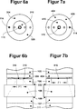
In den
Wie sich aus einem Vergleich der
Hieraus ergibt sich, dass bei dem ersten Klemmstückteil
Bei dem ersten Klemmstückteil
In
Das erste Klemmstückteil
In
Das erste Klemmstück
In
Wie insbesondere
In den
Im Gegensatz zu der in
Im Gegensatz zu dem zweiten Klemmstückteil
In
In
Darüber hinaus können auch weitere, alternative Formen der Umfangsformen der Kontaktfläche
Darüber hinaus ist die Zweiteilung des Klemmstück nicht auf das mit der Stützspindel verbindende Klemmstück beschränkt, sondern kann ergänzend oder alternativ auch für das mit der Antriebsspindel verbundene Klemmstück erreicht werden. In addition, the division of the clamping piece is not limited to the connecting with the support spindle clamping piece, but can be achieved in addition or alternatively for the connected to the drive spindle clamping piece.
Darüber hinaus können in die Klemmstückteile jeweilige Rückstelleinrichtungen integriert sein. In den
Dadurch, dass die Freiräume miteinander über den Kanal
In den
Die in der vorstehenden Beschreibung, in den Figuren und in den Ansprüchen beschriebenen Merkmale können sowohl einzeln als auch in beliebiger Kombination wesentlich für die Erfindung in ihren verschiedenen Ausführungsformen sein. The features described in the foregoing description, in the figures and in the claims may be essential to the invention in its various embodiments both individually and in any combination.
BezugszeichenlisteLIST OF REFERENCE NUMBERS
- 1 1
- Gehäuse casing
- 2 2
- Gehäuse casing
- 3 3
- Stützspindel support spindle
- 4 4
- Klemmstück clamp
- 5, 5‘ 5, 5 '
- Werkstück workpiece
- 7 7
- Klemmstück clamp
- 8, 8‘ 8, 8 '
- Spannfläche clamping surface
- 9, 9‘ 9, 9 '
- Spannfläche clamping surface
- 10 10
- Fräser milling cutter
- 11 11
- Antriebsspindel drive spindle
- 20 20
- Maschinengestell machine frame
- R R
- Achse axis
- K1 K1
- Klemmkraft clamping force
- K1a k 1a
- Kraftkomponente force component
- K1b k 1b
- Kraftkomponente force component
- α α
- Winkel angle
- 101, 501, 601, 701 101, 501, 601, 701
- Gehäuse casing
- 102, 502, 602, 702 102, 502, 602, 702
- Gehäuse casing
- 103, 503, 603, 703 103, 503, 603, 703
- Stützspindel support spindle
- 104, 204, 304, 404, 504, 804 104, 204, 304, 404, 504, 804
- Klemmstückteil Clamp part
- 105, 505, 605, 705 105, 505, 605, 705
- Werkstück workpiece
- 106, 206, 306, 406, 506, 606, 706 106, 206, 306, 406, 506, 606, 706
- Klemmstückteil Clamp part
- 107, 507, 607, 707 107, 507, 607, 707
- Klemmstück clamp
- 108, 508, 608, 708 108, 508, 608, 708
- Spannfläche clamping surface
- 109, 509, 609, 709 109, 509, 609, 709
- Spannfläche clamping surface
- 110, 510, 610. 710 110, 510, 610. 710
- Fräser milling cutter
- 111, 511, 611, 711 111, 511, 611, 711
- Antriebsspindel drive spindle
- 114 114
- Sicherungsstift safety pin
- 115 115
- Befestigungsschraube fixing screw
- 116, 216, 316, 416 116, 216, 316, 416
- Kontaktfläche contact area
- 119 119
- Klemmfläche clamping surface
- 120, 520, 620, 720 120, 520, 620, 720
- Maschinengestell machine frame
- 124 124
- Klemmfläche clamping surface
- 125, 225, 325, 425 125, 225, 325, 425
- Oberfläche surface
- 217, 317 217, 317
- Kontaktfläche contact area
- 227, 227 227, 227
- Oberfläche surface
- 421, 821 421, 821
- Lagerstift bearing pin
- 422, 822 422, 822
- Fluidkanal fluid channel
- 423, 823 423, 823
- Fluidanschluss fluid port
- 512, 612, 712 512, 612, 712
- Stufe step
- α' α '
- Winkel angle
- d1 d1
- Abstand distance
- F1, F2 F1, F2
- Fläche area
- A, B, C, D, E A, B, C, D, E
- Richtung direction
ZITATE ENTHALTEN IN DER BESCHREIBUNG QUOTES INCLUDE IN THE DESCRIPTION
Diese Liste der vom Anmelder aufgeführten Dokumente wurde automatisiert erzeugt und ist ausschließlich zur besseren Information des Lesers aufgenommen. Die Liste ist nicht Bestandteil der deutschen Patent- bzw. Gebrauchsmusteranmeldung. Das DPMA übernimmt keinerlei Haftung für etwaige Fehler oder Auslassungen.This list of the documents listed by the applicant has been generated automatically and is included solely for the better information of the reader. The list is not part of the German patent or utility model application. The DPMA assumes no liability for any errors or omissions.
Zitierte PatentliteraturCited patent literature
- DE 3214284 C2 [0002] DE 3214284 C2 [0002]
- DE 4237422 C2 [0003] DE 4237422 C2 [0003]
- DE 19701394 C1 [0004] DE 19701394 C1 [0004]
Claims (20)
Priority Applications (10)
| Application Number | Priority Date | Filing Date | Title |
|---|---|---|---|
| DE102012111473.0A DE102012111473A1 (en) | 2012-11-27 | 2012-11-27 | Workpiece holding device |
| CN201810959308.7A CN109015019B (en) | 2012-11-27 | 2013-11-26 | Workpiece fixing device and method for equipping a workpiece fixing device with workpieces |
| US14/647,696 US10160081B2 (en) | 2012-11-27 | 2013-11-26 | Workpiece holder device and method for mounting a workpiece in a workpiece holding device |
| CN201380071290.2A CN104936742B (en) | 2012-11-27 | 2013-11-26 | Work fixing device and for Work fixing device be equipped with workpiece method |
| PL13796058T PL2925487T3 (en) | 2012-11-27 | 2013-11-26 | Workpiece holder device and method for mounting a workpiece in a workpiece holding device |
| PCT/EP2013/074787 WO2014083017A2 (en) | 2012-11-27 | 2013-11-26 | Workpiece holder device and method for mounting a workpiece in a workpiece holding device |
| EP17168547.2A EP3219437B1 (en) | 2012-11-27 | 2013-11-26 | Workpiece holder device and method for mounting a workpiece in a workpiece holding device |
| JP2015543472A JP6482468B2 (en) | 2012-11-27 | 2013-11-26 | Workpiece holding device and method of attaching a workpiece to the workpiece holding device |
| EP13796058.9A EP2925487B1 (en) | 2012-11-27 | 2013-11-26 | Workpiece holder device and method for mounting a workpiece in a workpiece holding device |
| US16/178,272 US10953507B2 (en) | 2012-11-27 | 2018-11-01 | Workpiece holder device and method for mounting a workpiece in a workpiece holding device |
Applications Claiming Priority (1)
| Application Number | Priority Date | Filing Date | Title |
|---|---|---|---|
| DE102012111473.0A DE102012111473A1 (en) | 2012-11-27 | 2012-11-27 | Workpiece holding device |
Publications (1)
| Publication Number | Publication Date |
|---|---|
| DE102012111473A1 true DE102012111473A1 (en) | 2014-05-28 |
Family
ID=49674300
Family Applications (1)
| Application Number | Title | Priority Date | Filing Date |
|---|---|---|---|
| DE102012111473.0A Withdrawn DE102012111473A1 (en) | 2012-11-27 | 2012-11-27 | Workpiece holding device |
Country Status (7)
| Country | Link |
|---|---|
| US (2) | US10160081B2 (en) |
| EP (2) | EP3219437B1 (en) |
| JP (1) | JP6482468B2 (en) |
| CN (2) | CN109015019B (en) |
| DE (1) | DE102012111473A1 (en) |
| PL (1) | PL2925487T3 (en) |
| WO (1) | WO2014083017A2 (en) |
Cited By (2)
| Publication number | Priority date | Publication date | Assignee | Title |
|---|---|---|---|---|
| US10160081B2 (en) | 2012-11-27 | 2018-12-25 | Magerl Feinmechanik Gmbh | Workpiece holder device and method for mounting a workpiece in a workpiece holding device |
| CN114029763A (en) * | 2021-12-03 | 2022-02-11 | 重庆红江机械有限责任公司 | Composite drill clamp for machining spray hole of oil nozzle |
Families Citing this family (8)
| Publication number | Priority date | Publication date | Assignee | Title |
|---|---|---|---|---|
| CN104070388B (en) * | 2014-06-27 | 2016-08-24 | 天津铁路信号有限责任公司 | A kind of processing is positioned at the device in multiple upper different holes of workpiece |
| DE102014222423A1 (en) * | 2014-11-03 | 2016-05-04 | Homag Holzbearbeitungssysteme Gmbh | jig |
| JP7223571B2 (en) * | 2018-12-13 | 2023-02-16 | 川崎重工業株式会社 | ROBOT AND ROBOT SYSTEM INCLUDING THE SAME |
| CN109822375B (en) * | 2019-04-04 | 2020-11-03 | 歌尔股份有限公司 | Mounting rack and plane processing equipment and processing method thereof |
| CN112453945B (en) * | 2020-10-27 | 2022-06-14 | 成都飞机工业(集团)有限责任公司 | Hole making device and hole making method for deep-cylinder thin-wall part |
| CN113211132A (en) * | 2021-05-24 | 2021-08-06 | 马鞍山钢铁股份有限公司 | Sawing machine clamp device and clamping operation method |
| CN115502783B (en) * | 2021-12-31 | 2024-10-01 | 霍山嘉远智能制造有限公司 | Automatic tool for alignment of multiple workpieces |
| CN116619090B (en) * | 2023-07-25 | 2023-09-19 | 云科智能制造(沈阳)有限公司 | Horizontal machining center convenient to clamping work piece |
Citations (7)
| Publication number | Priority date | Publication date | Assignee | Title |
|---|---|---|---|---|
| DE3214284C2 (en) | 1982-04-19 | 1984-02-16 | Horst 6105 Ober-Ramstadt Schneider | Machine vice |
| DE4237422C2 (en) | 1991-12-18 | 1993-12-09 | Magerl Feinmechanik Gmbh | Workpiece holding device for workpieces to be machined on multiple sides on machine tools |
| DE19701394C1 (en) | 1997-01-16 | 1998-07-23 | Bernhard Magerl | Holding device for multi-sided workpieces |
| DE29900026U1 (en) * | 1999-01-04 | 1999-04-01 | Safeway Machinery Industry Corporation, Chingshui, Taichung | Double seat vice |
| WO2004054757A2 (en) * | 2002-12-16 | 2004-07-01 | Albert Frei | Workpiece fixing device |
| DE102009026389A1 (en) * | 2009-08-17 | 2011-03-03 | Grasch GbR (vertretungsberechtigter Gesellschafter Herr Johann Grassl, 73249 Wernau) | Method and clamping device for clamping a blank in a processing machine, in particular in a milling machine |
| DE202010008979U1 (en) * | 2010-11-08 | 2012-02-09 | Starrag Heckert Ag | Device for correcting the position of elements of a machine tool and compensating element therefor |
Family Cites Families (19)
| Publication number | Priority date | Publication date | Assignee | Title |
|---|---|---|---|---|
| FR1098489A (en) * | 1954-04-17 | 1955-07-27 | advanced vice with adjustable jaw | |
| JPS54178194U (en) * | 1978-06-06 | 1979-12-15 | ||
| US5157824A (en) * | 1987-04-17 | 1992-10-27 | Yamazaki Mazak Corporation | Opposed spindles lathe having tool rests movable in two different directions |
| US5175914A (en) * | 1987-04-28 | 1993-01-05 | Yamazaki Mazak Corporation | Machine tool having dual spindles and tool rests |
| US5097575A (en) * | 1987-04-17 | 1992-03-24 | Yamazaki Mazak Corporation | Complex machining machine tool |
| US4949444A (en) * | 1987-04-17 | 1990-08-21 | Yamazaki Mazak Corporation | Machine tool machining method |
| JPH0749164B2 (en) * | 1991-03-11 | 1995-05-31 | 大日金属工業株式会社 | Carriage structure in NC lathe |
| US5183272A (en) * | 1991-11-06 | 1993-02-02 | Tyvela Einar J | Universal chuck stop |
| JPH08309634A (en) * | 1995-05-11 | 1996-11-26 | Nachi Fujikoshi Corp | Rotary oscillating jig holder |
| JPH10249664A (en) * | 1997-03-05 | 1998-09-22 | Toyoda Mach Works Ltd | Floating holder |
| US20020109282A1 (en) * | 2000-12-13 | 2002-08-15 | Peck Loren Gary | Milling machine vise adjustable angle jaws |
| JP2004034240A (en) * | 2002-07-04 | 2004-02-05 | Mori Seiki Co Ltd | Machine tool clamping device |
| US7331093B2 (en) * | 2004-04-08 | 2008-02-19 | Dm2 Di Duina Gianfranco S.R.L. | Pieces hold-unit for workstations, transfer machines and like |
| DE102004036371C5 (en) * | 2004-07-23 | 2008-10-30 | Starragheckert Gmbh | Device for multi-side machining of workpieces |
| JP4410142B2 (en) * | 2005-04-22 | 2010-02-03 | 株式会社森精機製作所 | Compound lathe |
| WO2007126283A1 (en) | 2006-05-02 | 2007-11-08 | Sung-Rae Jo | Rotary table having a function of the dividing plate |
| AT506147B1 (en) * | 2007-12-13 | 2012-09-15 | Rainer Erne | POSITIONING DEVICE FOR FIXING A WORKPIECE |
| DE202009013241U1 (en) | 2009-10-02 | 2009-12-17 | Hofmann, Klaus | Workpiece console |
| DE102012111473A1 (en) | 2012-11-27 | 2014-05-28 | Magerl Feinmechanik Gmbh | Workpiece holding device |
-
2012
- 2012-11-27 DE DE102012111473.0A patent/DE102012111473A1/en not_active Withdrawn
-
2013
- 2013-11-26 CN CN201810959308.7A patent/CN109015019B/en active Active
- 2013-11-26 WO PCT/EP2013/074787 patent/WO2014083017A2/en active Application Filing
- 2013-11-26 US US14/647,696 patent/US10160081B2/en active Active
- 2013-11-26 EP EP17168547.2A patent/EP3219437B1/en active Active
- 2013-11-26 JP JP2015543472A patent/JP6482468B2/en active Active
- 2013-11-26 EP EP13796058.9A patent/EP2925487B1/en active Active
- 2013-11-26 CN CN201380071290.2A patent/CN104936742B/en not_active Expired - Fee Related
- 2013-11-26 PL PL13796058T patent/PL2925487T3/en unknown
-
2018
- 2018-11-01 US US16/178,272 patent/US10953507B2/en active Active
Patent Citations (7)
| Publication number | Priority date | Publication date | Assignee | Title |
|---|---|---|---|---|
| DE3214284C2 (en) | 1982-04-19 | 1984-02-16 | Horst 6105 Ober-Ramstadt Schneider | Machine vice |
| DE4237422C2 (en) | 1991-12-18 | 1993-12-09 | Magerl Feinmechanik Gmbh | Workpiece holding device for workpieces to be machined on multiple sides on machine tools |
| DE19701394C1 (en) | 1997-01-16 | 1998-07-23 | Bernhard Magerl | Holding device for multi-sided workpieces |
| DE29900026U1 (en) * | 1999-01-04 | 1999-04-01 | Safeway Machinery Industry Corporation, Chingshui, Taichung | Double seat vice |
| WO2004054757A2 (en) * | 2002-12-16 | 2004-07-01 | Albert Frei | Workpiece fixing device |
| DE102009026389A1 (en) * | 2009-08-17 | 2011-03-03 | Grasch GbR (vertretungsberechtigter Gesellschafter Herr Johann Grassl, 73249 Wernau) | Method and clamping device for clamping a blank in a processing machine, in particular in a milling machine |
| DE202010008979U1 (en) * | 2010-11-08 | 2012-02-09 | Starrag Heckert Ag | Device for correcting the position of elements of a machine tool and compensating element therefor |
Cited By (4)
| Publication number | Priority date | Publication date | Assignee | Title |
|---|---|---|---|---|
| US10160081B2 (en) | 2012-11-27 | 2018-12-25 | Magerl Feinmechanik Gmbh | Workpiece holder device and method for mounting a workpiece in a workpiece holding device |
| US10953507B2 (en) | 2012-11-27 | 2021-03-23 | Magerl Feinmechanik Gmbh | Workpiece holder device and method for mounting a workpiece in a workpiece holding device |
| CN114029763A (en) * | 2021-12-03 | 2022-02-11 | 重庆红江机械有限责任公司 | Composite drill clamp for machining spray hole of oil nozzle |
| CN114029763B (en) * | 2021-12-03 | 2024-01-19 | 重庆红江机械有限责任公司 | Composite drill clamp for processing spray hole of oil nozzle |
Also Published As
| Publication number | Publication date |
|---|---|
| CN109015019A (en) | 2018-12-18 |
| CN104936742A (en) | 2015-09-23 |
| EP2925487B1 (en) | 2017-05-03 |
| EP3219437B1 (en) | 2021-12-29 |
| US20150306721A1 (en) | 2015-10-29 |
| CN104936742B (en) | 2018-08-28 |
| JP6482468B2 (en) | 2019-03-13 |
| CN109015019B (en) | 2022-02-01 |
| EP2925487A2 (en) | 2015-10-07 |
| EP3219437A1 (en) | 2017-09-20 |
| US10160081B2 (en) | 2018-12-25 |
| US10953507B2 (en) | 2021-03-23 |
| WO2014083017A2 (en) | 2014-06-05 |
| PL2925487T3 (en) | 2017-12-29 |
| US20190099851A1 (en) | 2019-04-04 |
| JP2016501731A (en) | 2016-01-21 |
| WO2014083017A3 (en) | 2014-09-12 |
Similar Documents
| Publication | Publication Date | Title |
|---|---|---|
| DE102012111473A1 (en) | Workpiece holding device | |
| DE102011087282A1 (en) | Method for connecting two components and component connection | |
| WO2012010463A1 (en) | Zero point clamping device | |
| WO1992014945A1 (en) | Brake shoe | |
| DE102007037757A1 (en) | Adjustable punching die/punching mold for sheet metal component processing tool, has punch arranged eccentrically in inner ring that is eccentrically and rotatably arranged in outer ring, which is rotatably arranged in mounting ring | |
| DE102017001782B3 (en) | Module plate, machining center and method for clamping components | |
| WO2013153091A1 (en) | Roof bearing for a roof rack that can be fastened thereto | |
| DE102011108341A1 (en) | Clamping device for robot for clamping component, particularly work piece or work piece holder, such as work piece pallet, has receiving bore for receiving insert nipple which is attached at to-be clamped component | |
| EP3741501A1 (en) | Zero point clamping device | |
| EP1857197B1 (en) | Die for carrying out a mechanical joint | |
| EP3366417B1 (en) | Pull bolt of a zero point clamping system | |
| DE202017002479U1 (en) | positioning device | |
| EP3462042B1 (en) | Fastening assembly and component for such a fastening assembly | |
| DE102010022442A1 (en) | Attachment device e.g. armrest, for inner space of motor car, to receive drink container i.e. bottle, has rotary bearing moved away in axial direction of shaft during event of overload when attachment is pivoted around pivotal axis | |
| DE102016119952B4 (en) | Throwaway rotary brake | |
| EP1859909B1 (en) | Tool exchange device for robotic systems | |
| DE8335033U1 (en) | Coupling device | |
| DE102014102832A1 (en) | Connecting element for at least two plate-shaped elements of a tool, use of a connecting element and punching or stripping tool | |
| EP3344419A1 (en) | Torque wrench | |
| DE102016118535A1 (en) | Cylinder holder for a hydroforming device and hydroforming device | |
| DE102016211671A1 (en) | Switching unit and switching device with the switching unit | |
| DE202024102645U1 (en) | Device for placing workpieces and vice | |
| DE102013106094A1 (en) | Holding head of a device for holding a workpiece to be measured | |
| EP2732233A1 (en) | Securing device for fixing pins to a gun | |
| DE20120667U1 (en) | Deformable push button |
Legal Events
| Date | Code | Title | Description |
|---|---|---|---|
| R012 | Request for examination validly filed | ||
| R119 | Application deemed withdrawn, or ip right lapsed, due to non-payment of renewal fee |