DE102012105220A1 - Collimation method and apparatus for detectors - Google Patents
Collimation method and apparatus for detectors Download PDFInfo
- Publication number
- DE102012105220A1 DE102012105220A1 DE102012105220A DE102012105220A DE102012105220A1 DE 102012105220 A1 DE102012105220 A1 DE 102012105220A1 DE 102012105220 A DE102012105220 A DE 102012105220A DE 102012105220 A DE102012105220 A DE 102012105220A DE 102012105220 A1 DE102012105220 A1 DE 102012105220A1
- Authority
- DE
- Germany
- Prior art keywords
- collimator
- imaging system
- collimators
- plates
- radiation
- Prior art date
- Legal status (The legal status is an assumption and is not a legal conclusion. Google has not performed a legal analysis and makes no representation as to the accuracy of the status listed.)
- Ceased
Links
- 238000000034 method Methods 0.000 title claims abstract description 15
- 230000005855 radiation Effects 0.000 claims abstract description 44
- 238000003384 imaging method Methods 0.000 claims abstract description 42
- 238000004519 manufacturing process Methods 0.000 claims description 4
- 230000003716 rejuvenation Effects 0.000 claims description 3
- 239000011358 absorbing material Substances 0.000 claims description 2
- 238000002591 computed tomography Methods 0.000 description 10
- 230000006870 function Effects 0.000 description 5
- 239000000463 material Substances 0.000 description 5
- 238000003860 storage Methods 0.000 description 5
- 230000008569 process Effects 0.000 description 3
- 230000035945 sensitivity Effects 0.000 description 3
- 239000004593 Epoxy Substances 0.000 description 2
- 238000010586 diagram Methods 0.000 description 2
- 230000003287 optical effect Effects 0.000 description 2
- 230000009467 reduction Effects 0.000 description 2
- 230000001629 suppression Effects 0.000 description 2
- OKTJSMMVPCPJKN-UHFFFAOYSA-N Carbon Chemical compound [C] OKTJSMMVPCPJKN-UHFFFAOYSA-N 0.000 description 1
- 239000000853 adhesive Substances 0.000 description 1
- 230000001070 adhesive effect Effects 0.000 description 1
- 229910052799 carbon Inorganic materials 0.000 description 1
- 238000005266 casting Methods 0.000 description 1
- 230000008859 change Effects 0.000 description 1
- 238000004891 communication Methods 0.000 description 1
- 238000004590 computer program Methods 0.000 description 1
- 238000010276 construction Methods 0.000 description 1
- 230000006866 deterioration Effects 0.000 description 1
- 238000003745 diagnosis Methods 0.000 description 1
- 238000002059 diagnostic imaging Methods 0.000 description 1
- 229920006332 epoxy adhesive Polymers 0.000 description 1
- 230000007717 exclusion Effects 0.000 description 1
- 239000000945 filler Substances 0.000 description 1
- 239000011521 glass Substances 0.000 description 1
- 239000003292 glue Substances 0.000 description 1
- 238000011835 investigation Methods 0.000 description 1
- 238000012986 modification Methods 0.000 description 1
- 230000004048 modification Effects 0.000 description 1
- 238000000465 moulding Methods 0.000 description 1
- 230000010355 oscillation Effects 0.000 description 1
- 230000001575 pathological effect Effects 0.000 description 1
- 230000007170 pathology Effects 0.000 description 1
- 238000002600 positron emission tomography Methods 0.000 description 1
- 238000012545 processing Methods 0.000 description 1
- 238000002601 radiography Methods 0.000 description 1
- 238000005245 sintering Methods 0.000 description 1
- 238000012549 training Methods 0.000 description 1
Images

Classifications
-
- G—PHYSICS
- G21—NUCLEAR PHYSICS; NUCLEAR ENGINEERING
- G21K—TECHNIQUES FOR HANDLING PARTICLES OR IONISING RADIATION NOT OTHERWISE PROVIDED FOR; IRRADIATION DEVICES; GAMMA RAY OR X-RAY MICROSCOPES
- G21K1/00—Arrangements for handling particles or ionising radiation, e.g. focusing or moderating
- G21K1/02—Arrangements for handling particles or ionising radiation, e.g. focusing or moderating using diaphragms, collimators
- G21K1/025—Arrangements for handling particles or ionising radiation, e.g. focusing or moderating using diaphragms, collimators using multiple collimators, e.g. Bucky screens; other devices for eliminating undesired or dispersed radiation
Abstract
Es sind Verfahren und Vorrichtungen zur Kollimation von Detektoren in einem Bildgebungssystem geschaffen. Bildgebungssystem (400) enthält eine Strahlungsquelle (415), die eingerichtet ist, um eine Strahlung (416) von einem Brennfleck (262) auf ein Objekt zu projizieren, und mehrere Strahlungsdetektoren (420), die um wenigstens einen Abschnitt des Objekts (422) herum angeordnet sind. Die mehreren Strahlungsdetektoren (420) detektieren empfangene Strahlung (416) entlang eines von dem Brennfleck (262) zu den mehreren Detektoren (420) projizierten Pfads. Das Bildgebungssystem enthält ferner mehrere Kollimatoren (418), die zwischen dem Objekt (422) und den mehreren Detektoren (420) angeordnet sind, wobei die Kollimatoren (418) eine verjüngte (308, 264, 266) Konfiguration aufweisen.Methods and devices for collimating detectors in an imaging system are created. Imaging system (400) includes a radiation source (415) configured to project radiation (416) from a focal spot (262) onto an object and a plurality of radiation detectors (420) arranged around at least a portion of the object (422) are arranged around. The plurality of radiation detectors (420) detect received radiation (416) along a path projected from the focal spot (262) to the plurality of detectors (420). The imaging system also includes a plurality of collimators (418) disposed between the object (422) and the plurality of detectors (420), the collimators (418) having a tapered (308, 264, 266) configuration.
Description
HINTERGRUND ZU DER ERFINDUNGBACKGROUND TO THE INVENTION
Der hierin offenbarte Gegenstand bezieht sich allgemein auf hinter dem Objekt angeordnete Kollimatoren für Detektoren (z. B., Kollimatoren, die an den Detektoren angeordnet sind, die Röntgenstrahlen detektieren, nachdem diese einen Patienten durchdrungen haben) und spezieller auf Kollimatoren für Bildgebungsdetektoren, wie z. B. Computertomographie(CT)-Scanner.The subject matter disclosed herein relates generally to collimators disposed behind the object for detectors (eg, collimators disposed on the detectors that detect x-rays after they have penetrated a patient), and more particularly to collimators for imaging detectors, such as imaging detectors , B. Computed Tomography (CT) scanner.
Mehrschicht-Bildgebungsscanner, z. B. Mehrschicht-CT-Scanner, die eine erhöhte Geschwindigkeit und größere Abdeckungsbereiche aufweisen, können diagnostische Bilder mit höheren Auflösungen liefern. Es können beispielsweise Bilder mit mehr anatomischen Details oder diagnostisch relevanten Informationen geschaffen werden. Zum Beispiel können verschiedene für eine Diagnose interessierende Details kleine Strukturen, Merkmale und Objekte, die zu normaler Pathologie und zu verschiedenen pathologischen Zuständen gehören, sein. Einer der einschränkenden Faktoren bei der Visualisierung dieser kleinen Strukturen und Merkmale können jedoch die durch das Bildgebungssystem eingebrachten Artefakte sein. Insbesondere ist in medizinischen Bildgebungssystemen ein solcher bekannter einschränkender Faktor, der während einer Bildrekonstruktion Bildartefakte einbringen kann, eine Brennfleckdrift, die auch als Brennfleckbewegung bezeichnet wird.Multilayer imaging scanners, e.g. B. Multi-slice CT scanners, which have increased speed and coverage areas, can provide higher resolution diagnostic images. For example, images with more anatomical details or diagnostically relevant information can be created. For example, various details of interest for diagnosis may be small structures, features, and objects associated with normal pathology and various pathological conditions. However, one of the limiting factors in visualizing these small structures and features may be the artifacts introduced by the imaging system. In particular, in medical imaging systems, one such known limiting factor that can introduce image artifacts during image reconstruction is a focal spot drift, also referred to as focal spot motion.
Die Brennfleckbewegung kann durch verschiedene Faktoren verursacht sein, unter anderen z. B. durch die Bewegung des Gantrysystems relativ zu dem gescannten Objekt, Kalibrierungsfehler des Bildgebungssystems, Luftkalibrierungsfehler, Fehlausrichtung der Anode oder Verschlechterung des Glases der Röntgenstrahlröhre, Oszillation des Brennflecks aufgrund von mechanischen Vibrationen, thermische Veränderungen. Somit führt eine Reduktion der Brennfleckbewegung zu einer Reduktion von Artefakten in rekonstruierten Bildern.The focal spot movement can be caused by various factors, among others z. G., The movement of the gantry system relative to the scanned object, calibration error of the imaging system, air calibration error, misalignment of the anode or deterioration of the glass of the X-ray tube, oscillation of the focal spot due to mechanical vibrations, thermal changes. Thus, a reduction of the focal spot movement leads to a reduction of artifacts in reconstructed images.
Einige herkömmliche Bildgebungssysteme verwenden geschrägte Detektorkollimatoren, um den Detektor bezüglich der Brennfleckbewegung unempfindlich zu machen. Durch Schrägung des Kollimators wird eine Kollimation auf beiden Seiten eines Pixels erzielt. Diese schräg angesetzte Kollimation reduziert jedoch den Lichteinfang, weil die Röntgenstrahlenöffnung reduziert wird. Die Schrägung reduziert die geometrische Effizienz des Detektors aber verringert die Empfindlichkeit des Kollimators gegenüber geometrischen Toleranzen und der Brennfleckbewegung.Some conventional imaging systems use skewed detector collimators to render the detector insensitive to focal spot motion. Slanting the collimator produces collimation on both sides of a pixel. However, this skewed collimation reduces the light trapping because the X-ray aperture is reduced. The skewing reduces the geometric efficiency of the detector but reduces the sensitivity of the collimator to geometric tolerances and focal spot motion.
KURZBESCHREIBUNG DER ERFINDUNGBRIEF DESCRIPTION OF THE INVENTION
Gemäß einer Ausführungsform ist ein Bildgebungssystem geschaffen, das eine Strahlungsquelle, die eingerichtet ist, um eine Strahlung von einem Brennfleck auf ein Objekt zu projizieren, und mehrere Strahlungsdetektoren enthält, die um wenigstens einen Abschnitt des Objektes herum angeordnet sind. Die mehreren Strahlungsdetektoren detektieren empfangene Strahlung entlang eines von dem Brennfleck zu den mehreren Detektoren projizierten Pfads. Das Bildgebungssystem weist ferner mehrere Kollimatoren auf, die zwischen dem Objekt und den mehreren Detektoren angeordnet sind, wobei die Kollimatoren eine verjüngte Konfiguration aufweisen.In one embodiment, an imaging system is provided that includes a radiation source configured to project radiation from a focal spot onto an object and a plurality of radiation detectors disposed about at least a portion of the object. The plurality of radiation detectors detect received radiation along a path projected from the focal spot to the plurality of detectors. The imaging system further includes a plurality of collimators disposed between the object and the plurality of detectors, the collimators having a tapered configuration.
Gemäß einer weiteren Ausführungsform ist ein Verfahren zur Kollimation eines Strahlungsdetektors geschaffen. Das Verfahren enthält ein Anordnen mehrerer Strahlungsdetektoren, um wenigstens einen Abschnitt eines Objekts zu umgeben, und Vorsehen mehrerer Kollimatoren mit verjüngten Kanten zwischen dem Objekt und den mehreren Detektoren, wobei die mehreren Kollimatoren mit verjüngten Kanten konfiguriert sind, um die Bestrahlung der mehreren Strahlungsdetektoren gegenüber einem Bereich von Brennfleckpositionen zu erhöhen. Das Verfahren enthält ferner ein Konfigurieren der mehreren Strahlungsdetektoren zur Messung einer übertragenen Strahlung entlang eines von einem Brennfleck zu den mehreren Strahlungsdetektoren durch das Objekt projizierten Pfads.According to a further embodiment, a method for collimating a radiation detector is provided. The method includes arranging a plurality of radiation detectors to surround at least a portion of an object, and providing a plurality of tapered edge collimators between the object and the plurality of detectors, wherein the plurality of tapered edge collimators are configured to irradiate the plurality of radiation detectors Increase range of focal spot positions. The method further includes configuring the plurality of radiation detectors to measure transmitted radiation along a path projected from a focal spot to the plurality of radiation detectors through the object.
Gemäß einer noch weiteren Ausführungsform ist ein Verfahren zur Herstellung eines Kollimators für ein Bildgebungssystem geschaffen. Das Verfahren enthält ein Ausbilden mehrerer Kollimatorelemente, die Wände für mehrere Kanäle für den Kollimator definieren, und Schaffen einer verjüngten Neigung auf einer ersten Seite der mehreren Kollimatorelemente und einer verjüngten Neigung auf einer zweiten Seite der mehreren Kollimatorelemente.In yet another embodiment, a method of manufacturing a collimator for an imaging system is provided. The method includes forming a plurality of collimator elements defining walls for a plurality of channels for the collimator and providing a tapered slope on a first side of the plurality of collimator elements and a tapered slope on a second side of the plurality of collimator elements.
KURZBESCHREIBUNG DER ABBILDUNGENBRIEF DESCRIPTION OF THE FIGURES
Die Zeichnungen veranschaulichen allgemein beispielhaft, aber nicht einschränkend, verschiedene in dem vorliegenden Dokument beschriebene Ausführungsformen.The drawings illustrate, by way of example but not limitation, various embodiments described in this document.
DETAILLIERTE BESCHREIBUNG DER ERFINDUNGDETAILED DESCRIPTION OF THE INVENTION
Die vorstehende Kurzbeschreibung sowie die folgende detaillierte Beschreibung bestimmter Ausführungsformen des hierin dargelegten Gegenstands werden besser verstanden, wenn sie in Verbindung mit den beigefügten Zeichnungen gelesen werden. In dem hier verwendeten Sinne sollte ein Element oder Schritt, das bzw. der in der Einzahl angegeben und dem das Wort „ein” oder „eine” vorangestellt ist, nicht derart verstanden werden, dass es eine Mehrzahl dieser Elemente oder Schritte ausschließt, sofern ein derartiger Ausschluss nicht ausdrücklich angegeben ist. Außerdem sollen Bezugnahmen auf „eine Ausführungsform” nicht derart ausgelegt werden, als würden sie die Existenz weiterer Ausführungsformen ausschließen, die ebenfalls die angegebenen Merkmale enthalten. Darüber hinaus können, sofern nicht explizit das Gegenteil angegeben ist, Ausführungsformen, die ein Element oder mehrere Elemente mit einer bestimmten Eigenschaft „aufweisen” oder „enthalten”, weitere derartige Elemente enthalten, die diese Eigenschaft nicht haben.The foregoing summary, as well as the following detailed description of certain embodiments of the subject matter set forth herein, will be better understood when read in conjunction with the appended drawings. As used herein, an element or step prefixed to the singular and preceded by the word "a" or "an" should not be construed to exclude a plurality of such elements or steps, if any such exclusion is not expressly stated. In addition, references to "one embodiment" should not be construed as excluding the existence of further embodiments that also incorporate the recited features. Moreover, unless explicitly stated otherwise, embodiments that "comprise" or "contain" one or more elements having a particular property may include other such elements that do not have this property.
In der vorliegenden detaillierten Beschreibung wird auf die beigefügten Zeichnungen Bezug genommen, die einen Teil hiervon bilden und in welchen zur Veranschaulichung spezielle Ausführungsformen veranschaulicht sind, in denen der hierin offenbarte Gegenstand umgesetzt werden kann. Diese Ausführungsformen, auf die hierin auch als „Beispiele” Bezug genommen wird, sind ausreichend detailliert beschrieben, um einen gewöhnlichen Fachmann zu befähigen, den hierin offenbarten Gegenstand umzusetzen. Es soll verstanden werden, dass die Ausführungsformen in Kombination miteinander oder dass andere Ausführungsformen eingesetzt sein können und dass strukturelle, logische und elektrische Veränderungen ausgeführt werden können, ohne den Umfang des hierin offenbarten Gegenstands zu verlassen. Die folgende detaillierte Beschreibung soll deshalb nicht in einem einschränkenden Sinne verstanden werden, und der Umfang des hierin offenbarten Gegenstands ist durch die beigefügten Ansprüche und ihre Äquivalente definiert. In der folgenden Beschreibung werden gleiche Zahlen oder Bezugszeichen durchwegs zur Bezugnahme auf gleiche Teile oder Elemente verwendet. In diesem Dokument werden, wie in der Patentliteratur üblich, die Begriffe „ein” oder „eine” derart verwendet, dass sie ein oder mehr als eines umfassen. Sofern nicht anderweitig angezeigt wird, wird in diesem Dokument der Begriff „oder” als ein nicht exklusives ODER verwendet.In the following detailed description, reference is made to the accompanying drawings, which form a part hereof, and in which is shown by way of illustration specific embodiments in which the subject matter disclosed herein may be practiced. These embodiments, which are also referred to herein as "examples", are described in sufficient detail to enable one of ordinary skill in the art to implement the subject matter disclosed herein. It should be understood that the embodiments may be employed in combination with one another or that other embodiments may be employed and that structural, logical, and electrical changes may be made without departing from the scope of the subject matter disclosed herein. The following detailed description is therefore not intended to be in a limiting sense, and the scope of the subject matter disclosed herein is defined by the appended claims and their equivalents. In the following description, like numbers or numerals are used throughout to refer to like parts or elements. In this document, as is common in the patent literature, the terms "a" or "an" are used to include one or more than one. Unless otherwise indicated, the term "or" is used in this document as a non-exclusive OR.
Die obere Halterung
In einer Ausführungsform können der Brennfleck
Der Brennfleck
Es sollte beachtet werden, dass sich Brennfleck, wie hierin verwendet, allgemein auf einen Bereich bezieht, von dem aus Strahlungen projiziert werden oder von dem die Strahlungen ausgehen. Beispielsweise kann der Brennfleck
Der Brennfleck
Wie hierin verwendet, bezieht sich die Brennfleckbereich
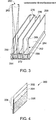
Somit sind in der veranschaulichten Ausführungsform die Kollimatorplatten
Im Betrieb ermöglichen die verjüngten Seiten
In einer Ausführungsform können die Kollimatorplatten
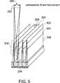
Insbesondere veranschaulicht
In einer Ausführungsform ist die Kollimatoranordnung
Die Kollimatorplatten
Die beiden Kollimatorplatten
Die Kollimatorplatten
Es sollte beachtet werden, dass verschiedene Herstellungsprozesse zur Erzeugung der Kollimatorplatten
Die stufenartige Anordnung definiert somit einen durch die verjüngte Kante
Es sollte beachtet werden, dass ein Bildgebungssystem mit Kollimatorausführungsformen mit verjüngter Kante zusätzlich zu der Reduktion der Bewegung des Brennflecks
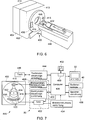
In einer Ausführungsform ist das Multimodalitäts-Bildgebungssystem
In einer Ausführungsform weist das Multimodalitäts-Bildgebungssystem
In einer alternativen Ausführungsform können die Kollimatoren
In einer Ausführungsform weist das Multimodalitäts-Bildgebungssystem
Die Detektorelemente
Während eines Scanns zur Akquisition von Röntgenprojektionsdaten, drehen sich die Gantry
Die Drehung der Gantry
Der Computer
In einer Ausführungsform enthält der Computer
Verschiedene hierin beschriebene Ausführungsformen ergeben ein greifbares und nicht flüchtiges Maschinen lesbares Medium oder Medien mit auf ihnen aufgezeichneten Anweisungen für einen Prozessor oder Computer, um eine Bildgebungsvorrichtung zu betreiben, um eine Ausführungsform eines hierin beschriebenen Verfahrens auszuführen. Das Medium oder die Medien können von beliebigem Typ einer CD-ROM, DVD, Diskette, Festplatte, optischer Disk, eines Flash-RAM-Laufwerks, oder ein anderer Typ eines Computer lesbaren Mediums oder eine Kombination von diesen sein.Various embodiments described herein provide a tangible and nonvolatile machine readable medium or media having instructions thereon for a processor or computer to operate an imaging device to perform one embodiment of a method described herein. The medium or media may be of any type of CD-ROM, DVD, floppy disk, hard disk, optical disk, flash RAM drive, or other type of computer readable medium, or a combination thereof.
Die verschiedenen Ausführungsformen und/oder Komponenten, z. B. der Monitor oder die Anzeige oder darin enthaltenen Komponenten und Controller können auch als Teil eines oder mehrerer Computer oder Prozessoren implementiert sein. Der Computer oder Prozessor kann eine Rechenvorrichtung, eine Eingabevorrichtung, eine Anzeigeeinheit und eine Schnittstelle beispielsweise für einen Zugriff auf das Internet enthalten. Der Computer oder Prozessor kann einen Mikroprozessor enthalten. Der Mikroprozessor kann mit einem Kommunikationsbus verbunden sein. Der Computer oder Prozessor kann ferner einen Speicher enthalten. Der Speicher kann einen Direktzugriffsspeicher (RAM) und einen Nur-Lese-Speicher (ROM) enthalten. Der Computer oder Prozessor kann ferner eine Speichervorrichtung enthalten, welche ein Festplattenlaufwerk oder ein Laufwerk für auswechselbare Speichermedien, wie z. B. ein Diskettenlaufwerk, Optoplattenlaufwerk und dergleichen, sein kann. Die Speichervorrichtung kann auch eine andere ähnliche Einrichtung zum Laden von Computerprogrammen oder anderen Instruktionen in den Computer oder Prozessor sein.The various embodiments and / or components, for. The monitor or display or components and controllers included therein may also be implemented as part of one or more computers or processors. The computer or processor may include a computing device, an input device, a display unit, and an interface for accessing the Internet, for example. The computer or processor may include a microprocessor. The microprocessor can communicate with a communication bus be connected. The computer or processor may further include a memory. The memory may include Random Access Memory (RAM) and Read Only Memory (ROM). The computer or processor may further include a storage device having a hard disk drive or a removable storage media drive such as a hard disk drive. A floppy disk drive, optical disk drive, and the like. The storage device may also be another similar device for loading computer programs or other instructions into the computer or processor.
Es soll verstanden werden, dass die vorstehende Beschreibung nur als veranschaulichend und nicht einschränkend gedacht ist. Beispielsweise können die vorstehend beschriebenen Ausführungsformen (und/oder Aspekte davon) in Kombination miteinander verwendet werden. Zusätzlich können viele Modifikationen ausgeführt werden, um eine spezielle Situation oder ein spezielles Material an die Lehren der Erfindung ohne Abweichung von deren Umfang anzupassen. Obwohl die hierin beschriebenen Abmessungen und Materialarten dafür gedacht sind, die Parameter der verschiedenen Ausführungsformen der Erfindung zu definieren, sind sie keineswegs einschränkend und stellen exemplarische Ausführungsformen dar. Viele weitere Ausführungsformen werden für den Fachmann nach Durchsicht der vorstehenden Beschreibung ersichtlich sein. Der Umfang der verschiedenen Ausführungsformen der Erfindung sollte daher unter Bezugnahme auf die beigefügten Ansprüche zusammen mit dem vollständigen Umfang von Äquivalenten, zu welchem derartige Ansprüche berechtigen, bestimmt werden. In den beigefügten Ansprüchen werden die Begriffe „enthaltend” und „in welcher” als die Äquivalente im Klartext für die entsprechenden Begriffe „aufweisend” und „worin” verwendet. Ferner werden in den nachstehenden Ansprüchen die Begriffe „erste”, „zweite” und „dritte”, usw. lediglich als Bezeichnungen verwendet und sollen keine numerischen Anforderungen bezüglich ihrer Objekte vorgeben. Ferner sind die Einschränkungen der nachstehenden Ansprüche nicht im Format Mittel-plus-Funktion geschrieben und sollen nicht auf der Basis von 35 U.S.C. § 112, 6. Absatz, interpretiert werden, sofern und soweit derartige Anspruchseinschränkungen nicht ausdrücklich den Ausdruck „Mittel für”, gefolgt von. einer Angabe einer Funktion ohne weitere Struktur verwenden.It should be understood that the foregoing description is intended to be illustrative and not restrictive. For example, the above-described embodiments (and / or aspects thereof) may be used in combination with each other. Additionally, many modifications may be made to adapt a particular situation or material to the teachings of the invention without departing from the scope thereof. Although the dimensions and types of materials described herein are intended to define the parameters of the various embodiments of the invention, they are by no means limitative and exemplary embodiments. Many other embodiments will be apparent to those skilled in the art after reviewing the foregoing description. The scope of the various embodiments of the invention should, therefore, be determined with reference to the appended claims, along with the full scope of equivalents to which such claims are entitled. In the appended claims, the terms "including" and "in which" are used as the equivalents in plain text for the corresponding terms "comprising" and "wherein". Furthermore, in the claims below, the terms "first," "second," and "third," etc. are used merely as terms and are not intended to dictate numerical requirements for their objects. Furthermore, the limitations of the following claims are not written in the medium plus function format and are not intended to be based on 35 U.S.C. § 112, 6th paragraph, unless and insofar as such claim limitations do not expressly use the term "means for", followed by. an indication of a function without further structure.
Diese schriftliche Beschreibung nutzt Beispiele, um die verschiedenen Ausführungsformen der Erfindung, einschließlich ihrer besten Ausführungsart, zu offenbaren und auch um es jedem Fachmann zu ermöglichen, die verschiedenen Ausführungsformen der Erfindung auszuführen, einschließlich der Herstellung und Verwendung jeglicher Vorrichtungen oder Systeme und der Ausführung jeglicher enthaltener Verfahren. Der patentierbare Umfang der verschiedenen Ausführungsformen der Erfindung ist durch die Ansprüche definiert und kann weitere Beispiele umfassen, die Fachleuten auf dem Gebiet einfallen. Derartige weitere Beispiele sollen innerhalb des Schutzumfangs der Ansprüche liegen, wenn sie Strukturelemente aufweisen, die sich von dem Wortsinn der Ansprüche nicht unterscheiden, oder wenn sie äquivalente Strukturelemente mit unwesentlichen Unterschieden gegenüber dem Wortsinn der Ansprüche enthalten.This written description uses examples to disclose the various embodiments of the invention, including the best mode, and also to enable any person skilled in the art to practice the various embodiments of the invention, including making and using any devices or systems and executing any of them Method. The patentable scope of the various embodiments of the invention is defined by the claims, and may include other examples that occur to those skilled in the art. Such other examples are intended to be within the scope of the claims if they have structural elements that do not differ from the literal language of the claims, or if they include equivalent structural elements with insubstantial differences from the literal languages of the claims.
Es sind Verfahren und Vorrichtungen zur Kollimation von Detektoren in einem Bildgebungssystem geschaffen. Ein Bildgebungssystem
BezugszeichenlisteLIST OF REFERENCE NUMBERS
- 100100
- Kollimatoranordnungcollimator
- 102102
- Wändewalls
- 104104
- obere Halterungupper bracket
- 106106
- untere Halterunglower bracket
- 108108
- KollimatorkanalKollimatorkanal
- 152152
- Detektorarraydetector array
- 154154
- Brennfleckfocal spot
- 156156
- Strahlenpfadbeam path
- 158158
- BrennfleckbereichFocal spot area
- 160160
- ursprüngliche Positionoriginal position
- 202202
- Brennfleckfocal spot
- 250250
- Plattenplates
- 252252
- verjüngte Kantetapered edge
- 254254
- Detektorendetectors
- 256256
- BasisBase
- 258258
- Oberseitetop
- 260260
- BrennfleckbereichFocal spot area
- 626626
- Brennfleckfocal spot
- 264264
- erste Seitefirst page
- 266266
- zweite Seitesecond page
- 268268
- Kanälechannels
- 270270
- Einlassöffnunginlet port
- 272272
- Auslassöffnungoutlet
- 300300
- Kollimatoranordnung mit verjüngten KantenCollimator arrangement with tapered edges
- 302302
- Kollimatorplattecollimator
- 304304
- Kollimatorplattecollimator
- 306306
- Kollimatorplattecollimator
- 308308
- verjüngte Kantetapered edge
- 400400
- Systemsystem
- 402402
- Modalitätseinheitmodality
- 404404
- Modalitätseinheitmodality
- 413413
- Gantrygantry
- 414414
- Gantrygantry
- 415415
- RöntgenstrahlquelleX-ray source
- 416416
- RöntgenstrahlenX-rays
- 418418
- Kollimatorencollimators
- 420420
- Detektorelementedetector elements
- 422422
- Subjektsubject
- 423423
- SystemsteuereinrichtungSystem controller
- 424424
- Kanälechannels
- 426426
- Untersuchungsachseexamination axis
- 428428
- RöntgenstrahlensteuereinrichtungX-ray control device
- 430430
- GantrymotorsteuereinrichtungGantrymotorsteuereinrichtung
- 432432
- DatenakquisitionssystemData acquisition system
- 434434
- BildrekonstruktionseinrichtungImage reconstruction means
- 436436
- Computercomputer
- 438438
- Speichervorrichtungstorage device
- 440440
- Bedienerworkstationoperator workstation
- 442442
- Anzeigedisplay
- 444444
- TischmotorsteuerungTable motor controller
- 446446
- motorisierter Tischmotorized table
- 448448
- Gantryöffnunggantry
- 450450
- Schreib-/Lese-VorrichtungWrite / read device
- 452452
- Computer lesbares MediumComputer readable medium
Claims (10)
Applications Claiming Priority (2)
| Application Number | Priority Date | Filing Date | Title |
|---|---|---|---|
| US13/163,367 US8571176B2 (en) | 2011-06-17 | 2011-06-17 | Methods and apparatus for collimation of detectors |
| US13/163,367 | 2011-06-17 |
Publications (1)
| Publication Number | Publication Date |
|---|---|
| DE102012105220A1 true DE102012105220A1 (en) | 2012-12-20 |
Family
ID=47228596
Family Applications (1)
| Application Number | Title | Priority Date | Filing Date |
|---|---|---|---|
| DE102012105220A Ceased DE102012105220A1 (en) | 2011-06-17 | 2012-06-15 | Collimation method and apparatus for detectors |
Country Status (3)
| Country | Link |
|---|---|
| US (1) | US8571176B2 (en) |
| JP (1) | JP6106371B2 (en) |
| DE (1) | DE102012105220A1 (en) |
Families Citing this family (11)
| Publication number | Priority date | Publication date | Assignee | Title |
|---|---|---|---|---|
| DE102011083394B4 (en) * | 2011-09-26 | 2017-11-02 | Siemens Healthcare Gmbh | Collimator, detector assembly and CT system |
| JP5977167B2 (en) * | 2012-12-26 | 2016-08-24 | ジーイー・メディカル・システムズ・グローバル・テクノロジー・カンパニー・エルエルシー | Radiation tomography equipment |
| US9086360B2 (en) | 2013-06-12 | 2015-07-21 | General Electric Company | Method and apparatus for thermal control in a CT detector |
| WO2015098631A1 (en) * | 2013-12-27 | 2015-07-02 | 株式会社 日立メディコ | Radiation detector and x-ray ct device |
| US9490099B2 (en) | 2014-08-20 | 2016-11-08 | Wisconsin Alumni Research Foundation | System and method for multi-source X-ray-based imaging |
| WO2016203954A1 (en) * | 2015-06-18 | 2016-12-22 | 株式会社日立製作所 | Radiation detector and x-ray ct apparatus provided therewith |
| CN106618617B (en) * | 2015-10-30 | 2021-12-21 | 通用电气公司 | X-ray detector and method for manufacturing same |
| EP3420562B1 (en) | 2016-02-25 | 2024-01-10 | Illinois Tool Works, Inc. | X-ray tube and gamma source focal spot tuning apparatus and method |
| US11350892B2 (en) * | 2016-12-16 | 2022-06-07 | General Electric Company | Collimator structure for an imaging system |
| US10492746B2 (en) | 2018-02-06 | 2019-12-03 | FMI Medical Systems Co., Ltd. | Spherical detector for CT system |
| CN109730712B (en) * | 2018-12-28 | 2022-08-09 | 深圳安科高技术股份有限公司 | CT bulb tube focus tracking method and system thereof |
Family Cites Families (10)
| Publication number | Priority date | Publication date | Assignee | Title |
|---|---|---|---|---|
| DE8621546U1 (en) * | 1986-08-11 | 1987-12-10 | Siemens Ag, 1000 Berlin Und 8000 Muenchen, De | |
| JPS6385484A (en) * | 1986-09-30 | 1988-04-15 | Toshiba Corp | Radiation detector |
| JP3442494B2 (en) * | 1994-09-02 | 2003-09-02 | ジーイー横河メディカルシステム株式会社 | X-ray CT system |
| JPH11218578A (en) * | 1998-02-02 | 1999-08-10 | Shimadzu Corp | Solid detector for computed tomography |
| US6385279B1 (en) | 1999-08-27 | 2002-05-07 | General Electric Company | Methods and apparatus for positioning a CT imaging x-ray beam |
| US20040120464A1 (en) | 2002-12-19 | 2004-06-24 | Hoffman David Michael | Cast collimators for CT detectors and methods of making same |
| US7492857B2 (en) | 2002-12-19 | 2009-02-17 | General Electric Company | Self-aligning scintillator-collimator assembly |
| US7655915B2 (en) * | 2003-05-13 | 2010-02-02 | General Electric Company | Collimator assembly for computed tomography system |
| US7031434B1 (en) | 2003-08-06 | 2006-04-18 | General Electric Company | Method of manufacturing, and a collimator mandrel having variable attenuation characteristics for a CT system |
| CN1929786A (en) | 2004-03-10 | 2007-03-14 | 皇家飞利浦电子股份有限公司 | Focused coherent-scatter computer tomography |
-
2011
- 2011-06-17 US US13/163,367 patent/US8571176B2/en active Active
-
2012
- 2012-06-13 JP JP2012133377A patent/JP6106371B2/en active Active
- 2012-06-15 DE DE102012105220A patent/DE102012105220A1/en not_active Ceased
Also Published As
| Publication number | Publication date |
|---|---|
| JP2013029495A (en) | 2013-02-07 |
| US20120321041A1 (en) | 2012-12-20 |
| JP6106371B2 (en) | 2017-03-29 |
| US8571176B2 (en) | 2013-10-29 |
Similar Documents
| Publication | Publication Date | Title |
|---|---|---|
| DE102012105220A1 (en) | Collimation method and apparatus for detectors | |
| DE102006005619A1 (en) | Method and systems for reducing over-illumination during spiral scanning | |
| DE69909196T2 (en) | Method and device for automatic noise reduction | |
| DE69931706T2 (en) | Z-axis trailing collimator with variable opening for computer tomography system | |
| DE102005018811B4 (en) | Aperture device for an X-ray device provided for scanning an object and method for a diaphragm device | |
| DE102013200337B4 (en) | Method, computer tomograph and computer program product for determining intensity values of an X-ray radiation for dose modulation | |
| DE69936769T2 (en) | IMAGE THICKNESS ELECTRICATION FOR MULTI-LAYER IMAGE DEVICE | |
| DE102011056347A1 (en) | Integrated X-ray detector assembly and method of making the same | |
| DE102010011581A1 (en) | Method for producing a 2D collimator element for a radiation detector and 2D collimator element | |
| DE19748891A1 (en) | Modifying slice thickness of imaging system during spiral scanning of object | |
| DE102012101568A1 (en) | Two-dimensional collimator module, X-ray detector and X-ray CT apparatus | |
| DE102012107136A1 (en) | Device for reducing scattering in CT imaging and method for its production | |
| DE102012108059A1 (en) | Dose reduction method in CT imaging and apparatus for its implementation | |
| DE102004032412A1 (en) | Projection truncation determining method for computed tomographic image reconstruction, involves calculating and averaging samples at projection view index, comparing average to threshold and determining projection truncated | |
| DE10361552A1 (en) | Volumetric CT system and method using multiple detector panels | |
| DE102012203086A1 (en) | Image processing device of a computer tomography system | |
| DE69937175T2 (en) | Device for dose verification in an imaging system | |
| DE102010061448A1 (en) | Calibration source and method for calibrating a nuclear medicine imaging system | |
| DE10157065A1 (en) | Method and device for providing additional computed tomography imaging modes | |
| DE102004022039A1 (en) | Collimator arrangement for a computed tomography system | |
| DE102014217569B4 (en) | Collimator module, detector module and method for manufacturing a collimator module | |
| DE19901901A1 (en) | CT scanning system for obtaining data from measurement signals and producing tomographic image | |
| DE102013214674A1 (en) | Determination of focus properties | |
| DE102012217940A1 (en) | Reconstruction of image data | |
| DE102007023925B4 (en) | Method, apparatus and arrangement for compensating the effects of focal spot migration when taking X-ray projection images |
Legal Events
| Date | Code | Title | Description |
|---|---|---|---|
| R012 | Request for examination validly filed | ||
| R002 | Refusal decision in examination/registration proceedings | ||
| R003 | Refusal decision now final |