DE102012108059A1 - Dose reduction method in CT imaging and apparatus for its implementation - Google Patents

Dose reduction method in CT imaging and apparatus for its implementation Download PDF

Info

Publication number
DE102012108059A1
DE102012108059A1 DE201210108059 DE102012108059A DE102012108059A1 DE 102012108059 A1 DE102012108059 A1 DE 102012108059A1 DE 201210108059 DE201210108059 DE 201210108059 DE 102012108059 A DE102012108059 A DE 102012108059A DE 102012108059 A1 DE102012108059 A1 DE 102012108059A1
Authority
DE
Germany
Prior art keywords
detector array
ray
rays
detector
loop filter
Prior art date
Legal status (The legal status is an assumption and is not a legal conclusion. Google has not performed a legal analysis and makes no representation as to the accuracy of the status listed.)
Withdrawn
Application number
DE201210108059
Other languages
German (de)
Inventor
Jiang Hsieh
Abdelaziz Ikhlef
Paavana Sainath
Xiaoye Wu
Roman Melnyk
Current Assignee (The listed assignees may be inaccurate. Google has not performed a legal analysis and makes no representation or warranty as to the accuracy of the list.)
General Electric Co
Original Assignee
General Electric Co
Priority date (The priority date is an assumption and is not a legal conclusion. Google has not performed a legal analysis and makes no representation as to the accuracy of the date listed.)
Filing date
Publication date
Application filed by General Electric Co filed Critical General Electric Co
Publication of DE102012108059A1 publication Critical patent/DE102012108059A1/en
Withdrawn legal-status Critical Current

Links

Images

Classifications

    • AHUMAN NECESSITIES
    • A61MEDICAL OR VETERINARY SCIENCE; HYGIENE
    • A61BDIAGNOSIS; SURGERY; IDENTIFICATION
    • A61B6/00Apparatus for radiation diagnosis, e.g. combined with radiation therapy equipment
    • A61B6/02Devices for diagnosis sequentially in different planes; Stereoscopic radiation diagnosis
    • A61B6/03Computerised tomographs
    • A61B6/032Transmission computed tomography [CT]
    • AHUMAN NECESSITIES
    • A61MEDICAL OR VETERINARY SCIENCE; HYGIENE
    • A61BDIAGNOSIS; SURGERY; IDENTIFICATION
    • A61B6/00Apparatus for radiation diagnosis, e.g. combined with radiation therapy equipment
    • A61B6/06Diaphragms
    • AHUMAN NECESSITIES
    • A61MEDICAL OR VETERINARY SCIENCE; HYGIENE
    • A61BDIAGNOSIS; SURGERY; IDENTIFICATION
    • A61B6/00Apparatus for radiation diagnosis, e.g. combined with radiation therapy equipment
    • A61B6/54Control of apparatus or devices for radiation diagnosis
    • A61B6/542Control of apparatus or devices for radiation diagnosis involving control of exposure
    • AHUMAN NECESSITIES
    • A61MEDICAL OR VETERINARY SCIENCE; HYGIENE
    • A61BDIAGNOSIS; SURGERY; IDENTIFICATION
    • A61B6/00Apparatus for radiation diagnosis, e.g. combined with radiation therapy equipment
    • A61B6/40Apparatus for radiation diagnosis, e.g. combined with radiation therapy equipment with arrangements for generating radiation specially adapted for radiation diagnosis
    • A61B6/4064Apparatus for radiation diagnosis, e.g. combined with radiation therapy equipment with arrangements for generating radiation specially adapted for radiation diagnosis specially adapted for producing a particular type of beam
    • A61B6/4078Fan-beams
    • AHUMAN NECESSITIES
    • A61MEDICAL OR VETERINARY SCIENCE; HYGIENE
    • A61BDIAGNOSIS; SURGERY; IDENTIFICATION
    • A61B6/00Apparatus for radiation diagnosis, e.g. combined with radiation therapy equipment
    • A61B6/50Clinical applications
    • A61B6/503Clinical applications involving diagnosis of heart

Abstract

Ein CT-System (10) weist eine Röntgenstrahlungsquelle (14), die so gestaltet ist, dass sie ein Röntgenstrahlenbündel (16) in Richtung auf ein Objekt (22) projiziert, ein Detektor-Array (18) und ein Schleifenfilter (29) auf. Das Schleifenfilter (29) weist auf: eine erste Röntgenstrahlung-Filterregion (102), die so positioniert ist, dass sie Röntgenstrahlen (120) dämpft, die durch einen Isokanal (124) des Detektor-Arrays (18) verlaufen; eine zweite Röntgenstrahlung-Filterregion (104), die so positioniert ist, dass sie Röntgenstrahlen (112) dämpft, die durch Kanäle des Detektor-Arrays (18) verlaufen, die in einer Kanalrichtung (130) exzentrisch zum Isokanal (124) angeordnet sind; und ein Röntgenstrahlung dämpfendes Material (110), das so positioniert werden kann, dass es die Röntgenstrahlen (112) dämpft, die durch die Kanäle des Detektor-Arrays (18) verlaufen, die in der Kanalrichtung (130) exzentrisch zum Isokanal (124) angeordnet sind. Das CT-System (10) weist außerdem ein Datenerfassungssystem (DAS) (32), das mit dem Detektor-Array (18) verbunden ist und so gestaltet ist, dass es Ausgangssignale vom Detektor-Array (18) empfängt, und einen Computer (36) auf, der so programmiert ist, dass er Projektionen von Bilddaten des Objekts empfängt und ein Bild des Objekts (22) unter Verwendung der Bilddaten erzeugt.A CT system (10) includes an x-ray source (14) configured to project an x-ray beam (16) toward an object (22), a detector array (18), and a loop filter (29) , The loop filter (29) comprises: a first x-ray filter region (102) positioned to attenuate x-rays (120) passing through an isochannel (124) of the detector array (18); a second x-ray filter region (104) positioned to attenuate x-rays (112) passing through channels of the detector array (18) located in a channel direction (130) eccentric to the isocanal (124); and an x-ray attenuating material (110) that is positionable to attenuate the x-rays (112) passing through the channels of the detector array (18) that are eccentric to the isocanal (124) in the channel direction (130). are arranged. The CT system (10) also includes a data acquisition system (DAS) (32) connected to the detector array (18) and configured to receive output signals from the detector array (18) and a computer (FIG. 36) programmed to receive projections of image data of the object and to generate an image of the object (22) using the image data.

Description

ALLGEMEINER TECHNISCHER HINTERGRUND GENERAL TECHNICAL BACKGROUND

Ausführungsformen der Erfindung betreffen allgemein eine diagnostische Bildgebung und insbesondere ein Verfahren und eine Vorrichtung zur Dosisverringerung in einer Bildgebungsanwendung. Embodiments of the invention relate generally to diagnostic imaging, and more particularly to a method and apparatus for dose reduction in an imaging application.

In computertomographischen (CT-)Bildgebungssystemen emittiert in der Regel eine Röntgenstrahlungsquelle ein fächerförmiges Strahlenbündel in Richtung auf eine Person oder ein Objekt, beispielsweise einen Patienten oder ein Gepäckstück. Im Folgenden beinhalten die Ausdrücke „Person“ und „Objekt“ jeden der bzw. alles was abgebildet werden kann. Nachdem das Strahlenbündel von dem Objekt abgeschwächt bzw. gedämpft worden ist, trifft es auf ein Feld bzw. Array von Strahlungsdetektoren. Die Stärke der abgeschwächten Strahlung des Strahlenbündels, das am Detektor-Array aufgefangen wird, hängt in der Regel von der Abschwächung des Röntgenstrahlenbündels durch das Objekt ab. Jedes Detektorelement des Detektor-Arrays erzeugt ein eigenes elektrisches Signal, welches das abgeschwächte Strahlenbündel anzeigt, das vom jeweiligen Detektorelement aufgefangen wird. Die elektrischen Signale werden zur Analyse zu einem Datenverarbeitungssystem gesendet, das schließlich ein Bild erzeugt. In computed tomography (CT) imaging systems, an x-ray source typically emits a fan-shaped beam towards a person or object, such as a patient or a piece of luggage. In the following, the terms "person" and "object" include any and all that can be mapped. After the beam has been attenuated by the object, it encounters an array of radiation detectors. The strength of the attenuated radiation of the beam collected at the detector array usually depends on the attenuation of the x-ray beam by the object. Each detector element of the detector array generates its own electrical signal indicative of the attenuated beam collected by the respective detector element. The electrical signals are sent to a data processing system for analysis, which finally generates an image.

Allgemein rotieren die Röntgenstrahlungsquelle und das Detektor-Array innerhalb einer Bildgebungsebene um die Gantry und um das Objekt. Röntgenstrahlungsquellen beinhalten in der Regel Röntgenröhren, die das Röntgenstrahlenbündel an einem Fokalpunkt emittieren. Röntgenstrahlungsdetektoren beinhalten in der Regel einen Kollimator zum Parallelrichten von Röntgenstrahlenbündeln, die am Detektor aufgefangen werden, einen dem Kollimator benachbarten Szintillator zum Umwandeln von Röntgenstrahlung in Lichtenergie und Photodioden zum Auffangen der Lichtenergie vom benachbarten Szintillator und zum Erzeugen von elektrischen Signalen daraus. Generally, the x-ray source and the detector array rotate within an imaging plane around the gantry and around the object. X-ray sources typically include x-ray tubes that emit the x-ray beam at a focal point. X-ray detectors typically include a collimator for collimating X-ray beams collected at the detector, a scintillator adjacent to the collimator for converting X-rays into light energy, and photodiodes for collecting the light energy from the adjacent scintillator and generating electrical signals therefrom.

In der Regel wandelt jeder Szintillator eines Szintillator-Arrays Röntgenstrahlung in Lichtenergie um. Jeder Szintillator gibt Energie an eine ihm benachbarte Photodiode ab. Jede Photodiode erfasst die Lichtenergie und erzeugt ein entsprechendes elektrisches Signal. Die Ausgangssignale der Photodioden werden dann zur Rekonstruktion des Bildes an das Datenverarbeitungssystem gesendet. In general, each scintillator of a scintillator array converts X-rays into light energy. Each scintillator delivers energy to an adjacent photodiode. Each photodiode detects the light energy and generates a corresponding electrical signal. The outputs of the photodiodes are then sent to the data processing system to reconstruct the image.

Die jüngsten Fortschritte der klinischen CT-Anwendungen lassen die Abdeckung bzw. Erfassung eines ganzen Organs in einer einzigen Gantry-Rotation und in einer einzigen Projektion wünschenswert erscheinen, so dass eine vollständige Aufnahme des Herzens in einem einzigen Herzzyklus durchgeführt werden kann. Ein Herz kann bei den meisten Patienten in der Regel in einer zylindrisch geformten Region mit einem Durchmesser von 25 cm (in einer X-Y-Ebene) und einer Länge von 12 cm (in einer Schicht- oder Z-Richtung) erfasst werden. Bei Neuronal-Perfusionsuntersuchungen ist es wünschenswert, mindestens 12 cm entlang der Längsachse des Patienten (in der Z-Richtung) abzudecken bzw. zu erfassen, während der Patient während einer Kontrastmittelaufnahme und -auswaschung kontinuierlich abgetastet bzw. gescannt wird. Es sind CT-Scanner auf dem Markt, die beispielsweise 16 cm entlang der Z-Achse und 50 cm Sichtfeld (Field of View, FOV) quer zum Patienten (in einer X-Y-Ebene) erfassen, was deutlich mehr ist als nötig, um Bildinformationen für Herz- und Neuronal-Perfusionsuntersuchungen zu liefern. Für Herz- und Neuronal-Perfusionsuntersuchungen ist daher die zu untersuchende Region bzw. die Region-of-Interest (ROI) in der X-Y-Ebene deutlich kleiner als der volle Detektorerfassungsbereich von 50 cm. The recent advances in clinical CT applications make it desirable to cover an entire organ in a single gantry rotation and in a single projection, so that complete uptake of the heart can be performed in a single cardiac cycle. For most patients, a heart can usually be detected in a cylindrically shaped region 25 cm in diameter (in an X-Y plane) and 12 cm in length (in a layer or Z direction). In neuronal perfusion studies, it is desirable to cover at least 12 cm along the longitudinal axis of the patient (in the Z direction) while the patient is continuously scanned during contrast media uptake and washout. There are CT scanners on the market that capture, for example, 16 cm along the Z axis and 50 cm field of view (FOV) across the patient (in an XY plane), which is significantly more than necessary for image information for heart and neuronal perfusion examinations. For heart and neuronal perfusion examinations, therefore, the region to be examined or the region-of-interest (ROI) in the X-Y plane is significantly smaller than the full detector detection range of 50 cm.

Das Abtasten bzw. Scannen eines Patienten mit einem FOV von 50 cm liefert jedoch häufig kaum zusätzliche relevante Bildinformationen und führt außerdem zu einer erhöhten Dosis für den Patienten. Die Kosten für einen solchen Scanner können diesen außerdem unerschwinglich machen. Unter Design-Gesichtspunkten ist es von Vorteil, den Erfassungsbereich auf ein FOV (in der X-Y-Ebene) zu reduzieren, das etwas größer ist als die Objekte, die untersucht werden sollen. Für CT-Rekonstruktionen sind jedoch Informationen von außerhalb der zu untersuchenden Region notwendig, um ein zu untersuchendes Objekt genau bzw. zuverlässig rekonstruieren zu können. Ohne diese Informationen kann es zu typischen Trunkierungsartefakten kommen. Obwohl in letzter Zeit Versuche unternommen wurden, Bilder auf Basis von trunkierten Projektionen zu rekonstruieren, ergeben diese Rekonstruktionsverfahren in der Regel instabile Lösungen oder erfordern spezielle Kenntnisse innerhalb des Rekonstruktions-FOV. However, scanning a patient with a 50 cm FOV often provides little additional relevant image information and also results in an increased dose for the patient. The cost of such a scanner can also make it unaffordable. From the design point of view, it is advantageous to reduce the coverage to a FOV (in the X-Y plane) that is slightly larger than the objects to be examined. For CT reconstructions, however, information from outside the region to be examined is necessary in order to accurately or reliably reconstruct an object to be examined. Without this information, typical truncation artifacts can occur. Although attempts have recently been made to reconstruct images based on truncated projections, these reconstruction techniques typically provide unstable solutions or require specialized knowledge within the reconstruction FOV.

Daher wäre es von Vorteil, eine Vorrichtung und ein Verfahren zu entwerfen, um eine Dosis bei der CT-Bildgebung zu verringern und gleichzeitig die Gesamtkosten für ein CT-System zu verringern. Therefore, it would be advantageous to design an apparatus and method to reduce a dose in CT imaging while reducing the overall cost of a CT system.

KURZFASSUNG DER ERFINDUNG SUMMARY OF THE INVENTION

Die Erfindung ist auf ein Verfahren und eine Vorrichtung zur Dosisverringerung gerichtet. The invention is directed to a method and apparatus for dose reduction.

Gemäß einem Aspekt weist ein CT-System auf: eine rotierbare Gantry mit einer Öffnung, um ein Objekt, das abgetastet bzw. gescannt werden soll, aufzunehmen, eine Röntgenstrahlungsquelle, die so gestaltet ist, dass sie ein Röntgenstrahlenbündel auf das Objekt projiziert, ein Detektor-Array mit einer Breite in einer Schichtrichtung, das so gestaltet ist, dass es Röntgenstrahlen erfasst, die das Objekt durchleuchten, und ein erstes Bowtie- oder Schleifenfilter, das zwischen der Röntgenstrahlungsquelle und der Öffnung angeordnet ist. Das erste Schleifenfilter weist auf: eine erste Röntgenstrahlung-Filterregion, die so angeordnet ist, dass sie Röntgenstrahlen abschwächt, die durch einen Isokanal des Detektor-Arrays verlaufen, eine zweite Röntgenstrahlung-Filterregion, die so angeordnet ist, dass sie Röntgenstrahlen abschwächt, die durch Kanäle des Detektor-Arrays verlaufen, die in einer Kanalrichtung exzentrisch zum Isokanal angeordnet sind, und ein Röntgenstrahlungs-Dämpfungsmaterial, das so positioniert werden kann, dass es die Röntgenstrahlen abschwächt, die durch die Kanäle des Detektor-Arrays verlaufen, die in der Kanalrichtung exzentrisch zum Isokanal angeordnet sind. Das CT-System weist auch ein Datenerfassungssystem (DAS), das mit dem Detektor-Array verbunden ist und so gestaltet ist, dass es Ausgangssignale vom Detektor-Array empfängt, und einen Computer auf, der so programmiert ist, dass er Projektionen von Bilddaten des Objekts vom DAS empfängt und ein Bild des Objekts unter Verwendung der Bilddaten erzeugt. In one aspect, a CT system comprises a rotatable gantry having an opening for receiving an object to be scanned, an x-ray source configured to project an x-ray beam onto the object, a detector Array having a width in a slice direction that is designed to capture x-rays that make up the object and a first bowtie or loop filter located between the X-ray source and the aperture. The first loop filter includes: a first x-ray filter region arranged to attenuate x-rays passing through an isocanal of the detector array; a second x-ray filter region arranged to attenuate x-rays passing through Pass channels of the detector array, which are arranged in a channel direction eccentric to the Isokanal, and an X-ray attenuation material that can be positioned so that it attenuates the X-rays passing through the channels of the detector array, which are eccentric in the channel direction are arranged to the Isokanal. The CT system also includes a data acquisition system (DAS) connected to the detector array and configured to receive output signals from the detector array and a computer programmed to receive projections of image data from the detector array Receives object from the DAS and generates an image of the object using the image data.

Gemäß einem anderen Aspekt beinhaltet ein Verfahren zur CT-Bildgebung das Projizieren eines Röntgenstrahlenbündels durch einen mittleren bzw. innen liegenden Abschnitt eines Schleifenfilters und auf einen mittleren bzw. innen liegenden Abschnitt eines Detektor-Arrays, der einen Isokanal des Detektor-Arrays enthält, und das Projizieren des Röntgenstrahlenbündels durch einen ersten, nicht innen liegenden Abschnitt des Schleifenfilters zu einem ersten, nicht innen liegenden Abschnitt des Detektor-Arrays, wobei der erste, nicht innen liegende Abschnitt des Schleifenfilters in einer Kanalrichtung versetzt zum innen liegenden Abschnitt des Schleifenfilters angeordnet ist, und wobei an dem ersten, nicht innen liegenden Abschnitt des Schleifenfilters ein Röntgenstrahlung dämpfendes Material befestigt ist. In another aspect, a method of CT imaging includes projecting an x-ray beam through an interior portion of a loop filter and onto an interior portion of a detector array that includes an isochannel of the detector array and Projecting the X-ray beam through a first, non-inner portion of the loop filter to a first, non-inner portion of the detector array, the first, non-inner portion of the loop filter being disposed in a channel direction offset from the inner portion of the loop filter, and wherein an X-ray attenuating material is attached to the first non-internal portion of the loop filter.

Ein weiterer Aspekt betrifft ein nicht-flüchtiges, Computer-lesbares Speichermedium, auf dem ein Computerprogramm gespeichert ist, das Befehle enthält, die, wenn sie von einem Computer ausgeführt werden, bewirken, dass der Computer: Röntgenbilddaten abfrägt, die in einem Detektor aufgrund von Röntgenstrahlen erzeugt werden, die durch eine mittlere Region eines ersten Abschnitts eines Schleifenfilters hindurch verlaufen, die eine erste zu untersuchende Region (ROI) definiert und einen Isokanal des Detektors enthält; Röntgenbilddaten abfrägt, die in dem Detektor aufgrund von Röntgenstrahlen erzeugt werden, die durch zwei Regionen des ersten Abschnitts des Schleifenfilters hindurch verlaufen, wobei die zwei Regionen in entgegengesetzten Kanalrichtungen zum Isokanal versetzt sind und wobei die Röntgenbilddaten aus den zwei Regionen des Schleifenfilters aufgrund von Röntgenstrahlen erzeugt werden, die durch ein Röntgenstrahlung dämpfendes Material hindurch verlaufen, das sich von einem Material des Schleifenfilters unterscheidet; und unter Verwendung der Röntgenbilddaten ein Bild erzeugt. Another aspect relates to a non-transitory computer-readable storage medium having stored thereon a computer program containing instructions that, when executed by a computer, cause the computer to: interrogate X-ray image data collected in a detector due to X-rays passing through a central region of a first portion of a loop filter defining a first region of interest (ROI) and including an isochannel of the detector; Interrogating X-ray image data generated in the detector due to X-rays passing through two regions of the first section of the loop filter, the two regions being offset in opposite channel directions to the Isocanal and the X-ray image data being generated from the two regions of the loop filter due to X-rays passing through an X-ray attenuating material different from a material of the loop filter; and generate an image using the X-ray image data.

Verschiedene andere Merkmale und Vorteile gehen aus der folgenden ausführlichen Beschreibung und den Zeichnungen hervor. Various other features and advantages will become apparent from the following detailed description and drawings.

KURZE BESCHREIBUNG DER ZEICHNUNGEN BRIEF DESCRIPTION OF THE DRAWINGS

Die Zeichnungen zeigen bevorzugte Ausführungsformen, die derzeit zur Ausführung der Erfindung in Betracht gezogen werden. The drawings show preferred embodiments which are currently contemplated for carrying out the invention.

In den Zeichnungen sind: In the drawings are:

1 eine bildliche Darstellung eines CT-Bildgebungssystems. 1 a pictorial representation of a CT imaging system.

2 ein Blockschema des in 1 dargestellten Systems. 2 a block diagram of in 1 illustrated system.

3 eine perspektivische Darstellung einer Ausführungsform eines Detektor-Arrays eines CT-Systems. 3 a perspective view of an embodiment of a detector array of a CT system.

4 eine perspektivische Darstellung einer Ausführungsform eines Detektors. 4 a perspective view of an embodiment of a detector.

5 eine Darstellung eines Schleifenfilters mit Röntgenstrahlung-Filterregionen gemäß einer Ausführungsform der Erfindung. 5 a representation of a loop filter with X-ray filter regions according to an embodiment of the invention.

6 eine Darstellung eines Beispiels für ein relatives Röntgenstrahlen-Stärkeprofil für ein gefiltertes Röntgenstrahlenbündel. 6 a representation of an example of a relative x-ray intensity profile for a filtered x-ray beam.

7 eine Darstellung eines Beispiels für einen ausgedünnten Röntgenstrahlungsdetektor gemäß einer Ausführungsform der Erfindung. 7 a representation of an example of a thinned X-ray detector according to an embodiment of the invention.

8 eine Darstellung eines anderen Beispiels für einen ausgedünnten Röntgenstrahlungsdetektor gemäß einer Ausführungsform der Erfindung. 8th 5 is an illustration of another example of a thinned X-ray detector according to an embodiment of the invention.

9 eine Darstellung eines Detektor-Arrays für einen Vollsichtfeld-(FOV)-Betriebsmodus und für einen Region-of-Interest-(ROI-)Betriebsmodus. 9 an illustration of a detector array for a full field of view (FOV) mode of operation and for a region of interest (ROI) mode of operation.

10 eine Darstellung eines Beispiels für eine Systemanordnung mit einem Schleifenfilter und einem Detektor zur Ausführung der beiden Betriebsmodi von 9. 10 a representation of an example of a system arrangement with a loop filter and a detector for carrying out the two operating modes of 9 ,

11 eine bildliche Darstellung eines CT-Systems zur Verwendung mit einem nicht-invasiven Paketuntersuchungssystem. 11 a pictorial representation of a CT system for use with a non-invasive package inspection system.

AUSFÜHRLICHE BESCHREIBUNG DER BEVORZUGTEN AUSFÜHRUNGSFORM DETAILED DESCRIPTION OF THE PREFERRED EMBODIMENT

Die Umgebung, in der die Erfindung zum Einsatz kommt, wird in Bezug auf ein computertomographisches (CT) System mit vierundsechzig Zeilen bzw. Schichten beschrieben. Für einen Fachmann wird es jedoch auf der Hand liegen, dass sich die Erfindung ebenso gut zur Verwendung mit anderen mehrschichtigen bzw. mehrzeiligen Konfigurationen eignet. Außerdem wird die Erfindung in Bezug auf die Erfassung und Umwandlung von Röntgenstrahlen beschrieben. Für einen Fachmann wird es jedoch auch auf der Hand liegen, dass sich die Erfindung genauso gut zur Erfassung und Umwandlung von hochfrequenter elektromagnetischer Energie eignet. Die Erfindung wird mit Bezug auf einen CT-Scanner der „dritten Generation“ beschrieben, eignet sich aber genauso gut für andere CT-Systeme. The environment in which the invention is used will be described with respect to a sixty-four line computer tomographic (CT) system. However, one skilled in the art will appreciate that the invention is equally well suited for use with other multilayer configurations. In addition, the invention will be described in relation to the detection and conversion of X-rays. However, it will be obvious to one skilled in the art that the invention is equally well suited for detecting and converting high frequency electromagnetic energy. The invention will be described with reference to a "third generation" CT scanner, but is equally well suited to other CT systems.
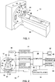
In 1 und 2 ist ein computertomographisches (CT-)Bildgebungssystem 10 dargestellt, das eine Gantry 12 aufweist, die einen CT-Scanner der „dritten Generation“ darstellt. Die Gantry 12 weist eine Röntgenstrahlungsquelle 14 auf, die ein Bündel von Röntgenstrahlen 16 in Richtung auf eine Detektoranordnung 18 auf der gegenüberliegenden Seite der Gantry 12 projiziert. Das Bildgebungssystem 10 weist einen vor dem Patienten angeordneten Kollimator 27 und einen Schleifen- bzw. Bowtie-Filter 29 auf. Die Detektoranordnung 18 besteht aus einer Mehrzahl von Detektoren 20 und Datenerfassungssystemen (DAS) 32. Die in Mehrzahl vorhandenen Detektoren 20 nehmen die projizierten Röntgenstrahlen 16 wahr, die den Patienten 22 durchleuchten. Das DAS 32 wandelt die Daten von den Detektoren 20 in digitale Signale zur weiteren Verarbeitung um. Jeder Detektor 20 erzeugt ein analoges elektrisches Signal, das die Stärke eines auftreffenden Röntgenstrahlenbündels und somit das abgeschwächte Strahlenbündel, das den Patienten 22 durchleuchtet hat, wiedergibt. Während einer Abtastung, mit der Röntgenstrahlungs-Projektionsdaten erfasst werden, drehen sich die Gantry 12 und die daran angebrachten Komponenten um eine Drehachse 24. In 1 and 2 is a computer tomographic (CT) imaging system 10 pictured a gantry 12 which represents a "third generation" CT scanner. The gantry 12 has an X-ray source 14 on that a bunch of x-rays 16 towards a detector array 18 on the opposite side of the gantry 12 projected. The imaging system 10 has a collimator arranged in front of the patient 27 and a bowtie filter 29 on. The detector arrangement 18 consists of a plurality of detectors 20 and Data Acquisition Systems (DAS) 32 , The majority of existing detectors 20 take the projected X-rays 16 true to the patient 22 illuminate. The the 32 converts the data from the detectors 20 into digital signals for further processing. Every detector 20 generates an analogue electrical signal indicative of the strength of an incident x-ray beam and thus the attenuated beam that illuminates the patient 22 has shone through. During a scan that captures X-ray projection data, the gantry rotates 12 and the components attached thereto about a rotation axis 24 ,

Die Drehung der Gantry 12 und der Betrieb der Röntgenstrahlungsquelle 14 werden von einem Steuermechanismus 26 des CT-Systems 10 gesteuert. Der Steuermechanismus 26 weist einen Controller 28 auf, der eine Röntgenstrahlungsquelle 14 mit Leistung und Zeitsteuersignalen versorgt und für eine Bewegungssteuerung zum Betreiben des vor dem Patienten angeordneten Kollimators 27 und des Schleifenfilters 29 sorgt, und der Steuermechanismus 26 weist einen Gantrymotor-Controller 30 auf, der die Umdrehungsgeschwindigkeit und die Position der Gantry 12 steuert. Ein Bildrekonstruktor 34 erhält ertastete und digitalisierte Röntgenstrahlungsdaten vom DAS 32 und führt eine Hochgeschwindigkeitsrekonstruktion durch. Das rekonstruierte Bild wird als Eingabe auf einen Computer 36 übertragen, der das Bild in einer Massenspeichervorrichtung 38 speichert. The rotation of the gantry 12 and the operation of the X-ray source 14 be from a control mechanism 26 of the CT system 10 controlled. The control mechanism 26 has a controller 28 on, which is an x-ray source 14 supplied with power and timing signals, and for motion control to operate the collimator disposed in front of the patient 27 and the loop filter 29 ensures, and the control mechanism 26 has a gantry motor controller 30 on, the speed of rotation and the position of the gantry 12 controls. An image reconstructor 34 obtains sampled and digitized X-ray data from the DAS 32 and performs a high-speed reconstruction. The reconstructed image is input to a computer 36 render the image in a mass storage device 38 stores.

Der Computer 36 empfängt außerdem über ein Bedienfeld 40, das irgendeine Art von Anwenderschnittstelle aufweist, beispielsweise eine Tastatur, eine Maus, einen sprachaktivierten Controller oder irgendeine andere geeignete Eingabevorrichtung, Befehle und Abtastungsparameter von einem Anwender. Eine zugehörige Anzeige 42 ermöglicht es dem Anwender, das rekonstruierte Bild und andere Daten vom Computer 36 zu betrachten. Die vom Anwender eingegebenen Befehle und Parameter werden vom Computer 36 verwendet, um dem DAS 32, dem Röntgenstrahlungs-Controller 28 und dem Gantrymotor-Controller 30 Steuersignale und Informationen zu liefern. Außerdem fungiert der Computer 36 als Tischmotor-Controller 44, der einen motorisierten Tisch 46 steuert, um einen Patienten 22 und eine Gantry zu positionieren. Insbesondere bewegt der Tisch 46 Patienten 22 vollständig oder teilweise durch eine Gantry-Öffnung 48 von 1. The computer 36 also receives via a control panel 40 having any type of user interface, such as a keyboard, a mouse, a voice activated controller, or any other suitable input device, commands, and sampling parameters from a user. An associated ad 42 allows the user to view the reconstructed image and other data from the computer 36 consider. The commands and parameters entered by the user are taken from the computer 36 used to the DAS 32 , the X-ray controller 28 and the gantry motor controller 30 To provide control signals and information. In addition, the computer acts 36 as a table motor controller 44 who has a motorized table 46 controls to a patient 22 and to position a gantry. In particular, the table moves 46 patients 22 fully or partially through a gantry opening 48 from 1 ,

Wie in der Technik allgemein bekannt ist, wird ein Patient 22 allgemein in einer Z-Richtung 21, die üblicherweise als eine Zeilen- bzw. Schichtrichtung der Gantry 12 bezeichnet wird, verschoben. Wie in der Technik ebenfalls allgemein bekannt ist, wird bewirkt, dass die Detektoranordnung 18 in einer X-Richtung 23 oder Kanalrichtung der Gantry 12 in Umfangsrichtung rotiert. Somit verlaufen Röntgenstrahlen 16 allgemein in einer Y-Richtung 25 und durch die Detektoranordnung 18, wenn sie von der Röntgenstrahlungsquelle 14 emittiert werden und den Patienten 22 durchleuchten. As is well known in the art, a patient becomes 22 generally in a Z direction 21 , which is usually a line or layer direction of the gantry 12 is called, moved. As is also well known in the art, the detector assembly is caused to effect 18 in an X direction 23 or channel direction of the gantry 12 rotated in the circumferential direction. Thus, X-rays are lost 16 generally in a Y direction 25 and by the detector arrangement 18 when viewed from the X-ray source 14 be emitted and the patient 22 illuminate.

Wie in 3 dargestellt ist, weist die Detektoranordnung 18 Schienen bzw. Leisten 17 auf. Üblicherweise kann die Detektoranordnung 18 Kollimationsblenden oder Platten 19 aufweisen, die dazwischen angeordnet sind. Die Platten 19 sind so angeordnet, dass sie die Röntgenstrahlen 16 parallel richten, bevor die Strahlenbündel beispielsweise auf den Detektor 20 von 4 auftreffen, der an der Detektoranordnung 18 positioniert ist. In einer Ausführungsform weist die Detektoranordnung 18 57 Detektoren 20, auf wobei jeder Detektor 20 eine Array-Größe von 64 × 16 Pixelelementen 50 aufweist. Infolgedessen weist die Detektoranordnung 18 64 Zeilen und 912 Spalten (16 × 57 Detektoren) auf, wodurch bei jeder Drehung der Gantry 12 64 Datenschichten bzw. -zeilen gleichzeitig erfasst werden können. Somit sind entsprechend 1 und 2 eine Z-Richtung (oder Schichtrichtung) 21, eine X-Richtung (oder Kanalrichtung) 23 und eine Y-Richtung 25 dargestellt. As in 3 is shown, the detector arrangement 18 Rails or strips 17 on. Usually, the detector arrangement 18 Collimation screens or plates 19 have, which are arranged therebetween. The plates 19 are arranged so that they have the x-rays 16 align in parallel before the beams, for example, on the detector 20 from 4 impinge on the detector assembly 18 is positioned. In one embodiment, the detector arrangement 18 57 detectors 20 , on each detector 20 an array size of 64x16 pixel elements 50 having. As a result, the detector arrangement 18 64 rows and 912 columns (16 × 57 detectors), which causes the gantry to rotate with each rotation 12 64 data layers or lines can be detected simultaneously. Thus are accordingly 1 and 2 a Z direction (or layer direction) 21 , an X direction (or channel direction) 23 and a Y direction 25 shown.

Wie in 4 dargestellt ist, weist der Detektor 20 ein DAS 32 auf, wobei jeder Detektor 20 eine Anzahl von Detektorelementen 50 aufweist, die in einer eng gepackten Gruppe bzw. Packung 51 angeordnet sind. Die Detektoren 20 weisen Stifte 52 auf, die innerhalb der Packung 51 in Bezug auf die Detektorelemente 50 angeordnet sind. Die Packung 51 ist an einem Rückseitenbeleuchtungs- bzw. Backlitdioden-Array 53 mit einer Mehrzahl von Dioden 59 angeordnet. Das Backlitdioden-Array 53 ist seinerseits auf einem Mehrschichtsubstrat 54 angeordnet. Abstandshalter 55 sind am Mehrschichtsubstrat 54 angeordnet. Die Detektorelemente 50 sind optisch mit einem Backlitdioden-Array 53 verbunden, und das Backlitdioden-Array 53 ist seinerseits elektrisch mit dem Mehrschichtsubstrat 54 verbunden. Flexible Schaltungen 56 sind an einer Fläche 57 des Mehrschichtsubstrats 54 und am DAS 32 befestigt. Die Detektoren 20 sind anhand der Stifte 52 innerhalb der Detektoranordnung 18 positioniert. As in 4 is shown, the detector has 20 a DAS 32 on, with each detector 20 a Number of detector elements 50 that in a tightly packed group or package 51 are arranged. The detectors 20 have pens 52 on that within the pack 51 with respect to the detector elements 50 are arranged. The package 51 is on a backlight diode or backlit diode array 53 with a plurality of diodes 59 arranged. The backlit diode array 53 is in turn on a multi-layer substrate 54 arranged. spacer 55 are at the multilayer substrate 54 arranged. The detector elements 50 are optically with a backlit diode array 53 connected, and the backlit diode array 53 is in turn electrically connected to the multilayer substrate 54 connected. Flexible circuits 56 are on a surface 57 of the multilayer substrate 54 and at the DAS 32 attached. The detectors 20 are based on the pens 52 within the detector array 18 positioned.

Während des Betriebs einer Ausführungsform erzeugen Röntgenstrahlen, die innerhalb der Detektorelemente 50 auftreffen, Photonen, die die Packung 51 durchqueren, wodurch ein analoges Signal erzeugt wird, das an einer Diode innerhalb des Backlitdioden-Arrays 53 erfasst wird. Das erzeugte analoge Signal wird durch das Mehrschichtsubstrat 54, durch die flexiblen Schaltungen 56 zum DAS 12 übertragen, wo das analoge Signal in ein digitales Signal umgewandelt wird. In Übereinstimmung mit den obigen Ausführungen definiert die Z-Richtung auch eine Schichtrichtung und, wie in der Technik bekannt ist, definiert die Anzahl der Detektorelemente 50, die in der Z-Richtung 21 im Detektor 20 angeordnet sind, die Anzahl der Bildschichten, die mit einem Bildgebungssystem, wie beispielsweise dem Bildgebungssystem 10 von 1 und 2, erhalten werden können. In der Regel kann die Anzahl der Schichten bzw. Zeilen oder Erfassungselemente 50 in der Z-Richtung 21 16, 64 oder 256 betragen. Es wird jedoch davon ausgegangen, dass die Erfindung nicht darauf beschränkt ist, und dass gemäß der Erfindung jede Anzahl von Zeilen in der X-Richtung 23 parallel gerichtet werden kann. Die X-Richtung oder Kanalrichtung 23 ist ebenfalls dargestellt, da sie auf den Detektor 20 bezogen ist. In der Regel weist jeder Detektor 20 16 Detektorelemente 50 in der X-Richtung 23 auf, und in der Regel sind 57 dieser Detektoren 20 in der Detektoranordnung 18 positioniert. Jedoch wird davon ausgegangen, dass die Erfindung nicht darauf beschränkt ist und dass gemäß der Erfindung jede Anzahl von Kanälen parallel gerichtet werden kann. Die Y-Richtung ist als Richtung 60 dargestellt, die allgemein parallel zum DAS 32 ist. During operation of one embodiment, x-rays generated within the detector elements 50 impinge, photons that the pack 51 through which an analog signal is generated at a diode within the backlit diode array 53 is detected. The generated analog signal is passed through the multilayer substrate 54 , through the flexible circuits 56 to the DAS 12 where the analog signal is converted to a digital signal. In accordance with the above, the Z direction also defines a layer direction and, as is known in the art, defines the number of detector elements 50 in the Z direction 21 in the detector 20 are arranged, the number of image layers, with an imaging system, such as the imaging system 10 from 1 and 2 , can be obtained. In general, the number of layers or rows or detection elements 50 in the Z direction 21 16, 64 or 256. It is understood, however, that the invention is not limited thereto and that according to the invention any number of lines in the X direction 23 can be aligned in parallel. The X direction or channel direction 23 is also shown as it is on the detector 20 is related. In general, each detector has 20 16 detector elements 50 in the X direction 23 on, and usually are 57 of these detectors 20 in the detector arrangement 18 positioned. However, it is believed that the invention is not limited thereto and that according to the invention any number of channels may be collimated. The Y direction is as direction 60 shown, which is generally parallel to the DAS 32 is.

Es wird erneut auf 3 Bezug genommen, wo drei als Beispiele dienende Detektoren 20 (auch als Detektormodule bezeichnet) (beispielsweise von den oben beschriebenen 57 Modulen) dargestellt sind. Während der Abbildung beispielsweise eines Patienten 22 von 1 und 2 kann eine zu untersuchende Region (ROI) 62 durch Abfragen von Bilddaten von den Detektoren 20, die an der Detektoranordnung 18 angebracht sind, abgebildet werden. Das heißt, während sich die Gantry 12 dreht, treten Röntgenstrahlen 16 aus der Quelle 14 aus, durchleuchten den Patienten 22 und werden von den Detektoren 20 aufgefangen. In der Regel werden Bilddaten der ROI 62 erfasst, während entweder ein Spiral- oder Axial-Scan durchgeführt wird, wie in der Technik bekannt ist. Üblicherweise wird ein am weitesten innen liegender bzw. zentraler Kanal, der in X-Richtung betrachtet im Zentrum der Detektoranordnung 18 liegt, als Isokanal oder Isozentrum definiert, der bzw. das Röntgenstrahlen auffängt, die entlang eines am weitesten innen liegenden bzw. mittleren Strahls 66 zur Detektoranordnung 18 verlaufen. Zur näheren Erläuterung und mit Bezug auf 2 zeigt der Strahl 66 den am weitesten innen liegenden Strahl 66, der allgemein durch die Drehachse 24 verläuft. It will be up again 3 Reference is made to where three exemplary detectors 20 (also referred to as detector modules) (for example, from the 57 modules described above). For example, during imaging of a patient 22 from 1 and 2 can a region to be examined (ROI) 62 by interrogating image data from the detectors 20 attached to the detector assembly 18 are attached to be mapped. That is, while the gantry 12 turns, X-rays kick 16 From the source 14 out, light up the patient 22 and are from the detectors 20 collected. In general, image data becomes the ROI 62 detected while performing either a spiral or axial scan, as is known in the art. Typically, a most innermost or central channel viewed in the X direction becomes the center of the detector array 18 is defined as an isocanal or isocenter that intercepts X-rays along an innermost or central beam 66 to the detector arrangement 18 run. For further explanation and with reference to 2 shows the beam 66 the innermost ray 66 generally by the axis of rotation 24 runs.

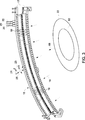
Gemäß der Erfindung wird einem vor dem Patienten angeordneten Kollimator eine Filterung hinzugefügt, um ein Signal außerhalb der ROI zu minimieren. Das kann dadurch geschehen, dass äußeren Kanalregionen eines Schleifenfilters wenige Millimeter dünne Dämpfungsplatten hinzugefügt werden, beispielsweise aus Aluminiumkupfer, die in der Regel eine Dämpfungswirkung pro Dickeneinheit aufweisend, die größer ist als die des eigentlichen Schleifenfilters. Wie in der Technik bekannt ist, kann ein typisches Schleifenfilter unter Verwendung von Aluminium, Kunststoff und anderen Materialien hergestellt werden, um ein kontrollierbares Maß an Dämpfung unter Verwendung von Materialien, die im Allgemeinen preiswert sind in der Herstellung, Bearbeitung und Verwendung, bereitzustellen. Gemäß einer Ausführungsform wird 3 mm starkes Kupfer außerhalb der ROI verwendet. So zeigt 5 ein Schleifenfilter 29, ein Detektor-Array 18, eine Röntgenstrahlungsquelle 14 und eine ROI 62, die einem System 10 entsprechen, und Komponenten, die in 1 bis 4 dargestellt sind, sind in perspektivischer Ansicht dargestellt. Um die Darstellung zu vereinfachen, sind andere Komponenten des Systems 10, beispielsweise die Gantry 12, nicht dargestellt. In accordance with the invention, filtering is added to a collimator located in front of the patient to minimize out-of-ROI signal. This can be done by adding to the outer channel regions of a loop filter thin damping plates a few millimeters thick, such as aluminum copper, which typically has a damping effect per unit thickness greater than that of the actual loop filter. As known in the art, a typical loop filter may be fabricated using aluminum, plastic, and other materials to provide a controllable level of cushioning using materials that are generally inexpensive to manufacture, process, and use. In one embodiment, 3 mm thick copper outside the ROI is used. So shows 5 a loop filter 29 , a detector array 18 , an X-ray source 14 and a ROI 62 that a system 10 correspond, and components that are in 1 to 4 are shown are shown in perspective view. To simplify the presentation are other components of the system 10 for example the gantry 12 , not shown.

Wie in 5 dargestellt ist, weist das System 10 einen Fokalpunkt 100 der Röntgenstrahlungsquelle 14 auf, von dem aus Röntgenstrahlen in Richtung auf ein Detektor-Array emittiert werden. Das Schleifenfilter 29 weist eine erste Röntgenstrahlung-Filterregion 102 und eine zweite Röntgenstrahlung-Filterregion 104 auf, die ihrerseits eine erste Unterregion 106 und eine zweite Unterregion 108 aufweist. Die Unterregionen 106, 108 weisen ein Röntgenstrahlung dämpfendes Material 110 auf, das so angeordnet ist, dass es Röntgenstrahlen 16, die von einem Fokalpunkt 100 aus durch Unterregionen 106, 108 und zum Detektor-Array 18 verlaufen, abschwächt. Genauer verlaufen Röntgenstrahlen 112, die durch die erste Unterregion 106 des Schleifenfilters 29 verlaufen, zu einer ersten Unterregion 114 des Detektor-Arrays 18, und Röntgenstrahlen 116, die durch die zweite Unterregion 108 des Schleifenfilters 29 verlaufen, verlaufen zu einer zweiten Unterregion 118 des Detektor-Arrays 18. Im Gegensatz dazu verlaufen Röntgenstrahlen 120, die durch eine erste Röntgenstrahlung-Filterregion 102 des Schleifenfilters 29 verlaufen, zu einer mittleren Detektorregion 122, die einen Isokanal 124 aufweist, der ein Kanal ist, der so angeordnet ist, dass er Röntgenstrahlen 16 auffängt, die entlang eines am weitesten innen liegenden bzw. mittleren Strahls 66 verlaufen. Wie bereits beschrieben, ist das Detektor-Array 18 elektrisch mit dem DAS 32 verbunden, das seinerseits mit einem Computer 36 verbunden ist. So ist der Computer 36 so programmiert, dass er Projektionen von Bilddaten vom DAS 32 erfasst, das so gestaltet ist, dass es Bilddaten vom Detektor-Array 18 erfasst. As in 5 is shown, the system assigns 10 a focal point 100 the X-ray source 14 from which X-rays are emitted towards a detector array. The loop filter 29 has a first X-ray filter region 102 and a second X-ray filter region 104 which, in turn, is a first sub-region 106 and a second subregion 108 having. The subregions 106 . 108 have an X-ray attenuating material 110 which is arranged to X-rays 16 from a focal point 100 out through subregions 106 . 108 and to the detector array 18 run, weakens. Accurate are X-rays 112 , by the first subregion 106 of the loop filter 29 to a first subregion 114 of the detector array 18 , and X-rays 116 passing through the second subregion 108 of the loop filter 29 run, run to a second subregion 118 of the detector array 18 , In contrast, X-rays run 120 passing through a first X-ray filter region 102 of the loop filter 29 run, to a central detector region 122 that has an Isokanal 124 which is a channel arranged to receive X-rays 16 which travels along an innermost or middle beam 66 run. As already described, the detector array is 18 electrically with the DAS 32 connected, in turn, with a computer 36 connected is. That's the computer 36 programmed to make projections of image data from the DAS 32 which is designed to capture image data from the detector array 18 detected.

Die mittlere Detektorregion 122 und die erste Unterregion 114 sind durch eine erste Abgrenzung 126 getrennt, und die mittlere Detektorregion 122 und die zweite Unterregion 118 sind durch eine zweite Abgrenzung 128 getrennt. So ist die erste Abgrenzung 126 in einer ersten Kanalrichtung 130, die mit der X-Richtung 23 zusammenfällt, entfernt vom Isokanal 124 angeordnet, und die zweite Abgrenzung 128 ist in einer zweiten Kanalrichtung 132, die ebenfalls mit der X-Richtung zusammenfällt, aber der ersten Kanalrichtung 130 entgegengesetzt ist, entfernt vom Isokanal 124 angeordnet. Die ersten und zweiten Röntgenstrahlung-Filterregionen 102, 104 werden zusammen mit den entsprechenden ersten und zweiten Detektorunterregionen 114, 118 und der mittleren Detektorregion 122 so ausgewählt, dass die ROI 62 von der ersten Röntgenstrahlung-Filterregion 102 und der mittleren Detektorregion 122 vollständig eingeschlossen wird. Ein Fachmann wird erkennen, dass die Größe der ROI 62 je nach dem abgebildeten Patienten variieren kann, und daher Röntgenstrahlung-Filterregionen 102, 104 und entsprechende Detektorunterregionen 114, 118 auf Basis eines Größenbereichs der ROI 62 ausgewählt werden können, der beispielsweise auf Grund des erwarteten klinischen Einsatzbereichs des Systems 10 zu erwarten ist. The middle detector region 122 and the first subregion 114 are by a first demarcation 126 separated, and the middle detector region 122 and the second subregion 118 are by a second demarcation 128 separated. So that's the first demarcation 126 in a first channel direction 130 that with the X direction 23 coincides, away from the Isokanal 124 arranged, and the second demarcation 128 is in a second channel direction 132 , which also coincides with the X direction, but the first channel direction 130 opposite, away from the Isokanal 124 arranged. The first and second X-ray filter regions 102 . 104 are together with the corresponding first and second detector subregions 114 . 118 and the middle detector region 122 so selected that the ROI 62 from the first X-ray filter region 102 and the middle detector region 122 is completely enclosed. A person skilled in the art will realize that the size of the ROI 62 may vary depending on the patient being imaged, and therefore X-ray filter regions 102 . 104 and corresponding detector subregions 114 . 118 based on a size range of the ROI 62 based, for example, on the expected clinical use of the system 10 is to be expected.

Da ein typischer kleiner Schleifenfilter ein 25 cm großes Scan-Sichtfeld (FOV) abdecken kann, beeinträchtigt die Hinzufügung von Röntgenstrahlung dämpfendem Material 110 die Funktionsfähigkeit des kleinen Schleifenfilters, beispielswiese des Schleifenfilters 29, nicht, wenn Objekte abgetastet werden. Gemäß einer Ausführungsform ist ein Röntgenstrahlung dämpfendes Material 110 ein positionierbares Material, das entweder dauerhaft oder abnehmbar (zum Austauschen des Materials 10) an den ersten und zweiten Unterregionen 106, 108 befestigt werden kann. Alternativ dazu kann gemäß einer anderen Ausführungsform Röntgenstrahlung dämpfendes Material 110 dynamisch hinzugefügt und entfernt werden, wenn beispielsweise ein Scan des Herzens erforderlich ist. Das heißt, das Röntgenstrahlung dämpfende Material 110 kann dynamisch neu positioniert und gesteuert werden, beispielsweise mit einem Controller 128 des Systems 10, so dass Röntgenstrahlen 112 und 116, wenn gewünscht, nur von den ersten und zweiten Unterregionen 106, 108 des Schleifenfilters 29 abgeschwächt werden und nicht durch das Röntgenstrahlung dämpfende Material 110. Since a typical small loop filter can cover a 25 cm scan field of view (FOV), the addition of X-ray attenuates attenuating material 110 the functionality of the small loop filter, for example the loop filter 29 , not when objects are being scanned. In one embodiment, an X-ray attenuating material 110 a positionable material that is either permanent or removable (for replacing the material 10 ) at the first and second subregions 106 . 108 can be attached. Alternatively, according to another embodiment, X-ray attenuating material 110 be dynamically added and removed, for example, when a scan of the heart is required. That is, the X-ray attenuating material 110 can be dynamically repositioned and controlled, for example with a controller 128 of the system 10 so that x-rays 112 and 116 if desired, only from the first and second subregions 106 . 108 of the loop filter 29 attenuated and not by the X-ray attenuating material 110 ,

In einer bevorzugten Ausführungsform verringert das Maß der Filterung, das von dem Röntgenstrahlung dämpfenden Material 110 bereitgestellt wird, wenn es in Verbindung mit den ersten und zweiten Unterregionen 106, 108 angeordnet wird, den Fluss der Röntgenstrahlung in den ersten und zweiten Unterregionen 114, 118, die in 5 dargestellt sind, um einen Faktor 20 oder mehr. Das heißt, die Strahlung außerhalb der ROI 62 kann im Vergleich zur Gesamtdosis im Wesentlichen vernachlässigt werden. 6 zeigt ein relatives Intensitätsprofil für ein 3 mm dickes Beispielsfilter. Für eine typische ROI 62, die vollständig von einer mittleren Region 122 eingeschlossen ist, können Bilddaten 62, die von einem Detektor-Array 18 in den ersten und zweiten Unterregionen 114, 118 außerhalb der mittleren Region 122 empfangen werden, wenig zusätzliche Informationen in den endgültigen Bildern liefern. Jedoch kann eine gewisse Menge an Röntgenstrahlenenergie außerhalb der mittleren Detektorregion 122 an Stellen 140 nützlich oder notwendig sein, um Trunkierungsfehler in den endgültigen Bildern zu vermeiden. Somit ist es von Vorteil, etwa die gesamte Energie zu empfangen, die von den Röntgenstrahlen 112, 116 empfangen wird, die in den ersten und zweiten Unterregionen 114, 118 empfangen werden. In a preferred embodiment, the amount of filtering reduces the material attenuating the X-ray radiation 110 is provided when in connection with the first and second subregions 106 . 108 is arranged, the flow of X-rays in the first and second subregions 114 . 118 , in the 5 represented by one factor 20 or more. That is, the radiation outside the ROI 62 can be essentially neglected compared to the total dose. 6 shows a relative intensity profile for a 3 mm thick sample filter. For a typical ROI 62 completely from a middle region 122 can be included image data 62 coming from a detector array 18 in the first and second subregions 114 . 118 outside the middle region 122 receive little additional information in the final images. However, some amount of x-ray energy may be outside the central detector region 122 in places 140 useful or necessary to avoid truncation errors in the final images. Thus, it is beneficial to receive about all the energy that comes from the X-rays 112 . 116 received in the first and second subregions 114 . 118 be received.

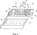
Gemäß einer Ausführungsform der Erfindung werden einige der Detektormodule aus der ROI entfernt, wie in 7 dargestellt ist, um die Kosten für den Detektor zu verringern. 7 zeigt eine Draufsicht auf das ausgedünnte Detektor-Array 18, das eine Konfiguration aufweist, aus der zwei von drei Modulen entfernt worden sind. Mittlere Module 150 entsprechen der mittleren Detektorregion 122, die in 5 dargestellt ist, die erste Unterregion 152 entspricht der ersten Unterregion 114 von 5, und die zweite Unterregion 154 entspricht der zweiten Unterregion 118 von 5. Gemäß dieser Ausführungsform sind mittlere Module 156 als funktionsfähige Module in der mittleren Detektorregion 122 ebenso wie in den Detektorunterregionen 152, 154 enthalten. Das heißt, in der Z-Richtung 21 und über die gesamte Länge der X-Richtung 23 des Detektor-Arrays 18 sind funktionsfähige Module enthalten, um für ein volles FOV zu sorgen, das sich über die ROI 62 hinaus erstreckt. Jedoch können in den Ecken des Detektor-Arrays 18 Modulstellen ausgedünnt sein. So sind Z-Abgrenzungen 158 durch vier Modul-Eckregionen 160 zwischen Z-Abgrenzungen 158 und Abgrenzungen 126, 128 gezogen. According to one embodiment of the invention, some of the detector modules are removed from the ROI, as in FIG 7 is shown to reduce the cost of the detector. 7 shows a plan view of the thinned detector array 18 having a configuration from which two out of three modules have been removed. Middle modules 150 correspond to the middle detector region 122 , in the 5 is shown, the first subregion 152 corresponds to the first subregion 114 from 5 , and the second subregion 154 corresponds to the second subregion 118 from 5 , According to this embodiment, middle modules are 156 as functional modules in the middle detector region 122 as well as in the detector subregions 152 . 154 contain. That is, in the Z direction 21 and over the entire length of the X direction 23 of the detector array 18 Functional modules are included to provide a full FOV that is beyond the ROI 62 extends beyond. However, in the corners of the detector array 18 Thinned out module spots. So are Z delineations 158 through four module corner regions 160 between Z boundaries 158 and demarcations 126 . 128 drawn.

Somit stellen funktionsfähige Module über einem vollen FOV, aber mit einem begrenzten Z-Erfassungsbereich, beispielsweise zwischen Z-Abgrenzungen
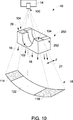
 158, eine Möglichkeit bereit, wie der Scanner Bilder von voller Wiedergabetreue im gesamten FOV erfassen kann. So wird in einem Betriebsmodus eine vor dem Patienten stattfindende parallele Ausrichtung in Z-Richtung 21 unter Verwendung beispielsweise eines Kollimators 27 ermöglicht, der in 1 und 2 dargestellt ist und der einer parallel gerichteten Breite entspricht, die einer Breite von mittleren Modulen 156 entspricht. In diesem Modus wird, um ein volles FOV zu erhalten, Röntgenstrahlung dämpfendes Material 110, das in 5 dargestellt ist, entweder entfernt, oder ein großes oder mittelgroßes Schleifenfilter wird verwendet, in dem keine dünnen Platten vorhanden sind. Thus, functional modules are over a full FOV, but with a limited Z-detection range, for example between Z-bounds 158 , one way in which the scanner can capture full-fidelity images throughout the FOV. Thus, in an operating mode, a parallel alignment in the Z-direction takes place in front of the patient 21 using, for example, a collimator 27 allows the in 1 and 2 is shown and corresponds to a parallel width, the width of a middle modules 156 equivalent. In this mode, to get a full FOV, X-ray attenuating material is used 110 , this in 5 is shown, either removed, or a large or medium-sized loop filter is used, in which no thin plates are present.

In den Eckregionen 160 von 5 stellen leere Blöcke 162 die Stelle dar, wo die Module entfernt worden sind, und Blöcke 164 stellen funktionsfähige Module dar, die sich darin befinden. Man beachte, dass die Aufgabe dieser Module in den Blöcken 164 darin besteht, im Allgemeinen ausreichende Informationen zu liefern, um Trunkierungsartefakte zu vermeiden, und daher heruntergestufte Module in diesen Regionen in den vier Eckregionen 160 verwendet werden können. Wenn ein Scan mit einer stärker begrenzten ROI gewünscht wird (beispielsweise um Bilddaten von einer ROI 62 zu erhalten), wird somit das gesamte Detektor-Array 18 mit Röntgenstrahlen 16 belichtet, wobei die äußeren Unterregionen 152, 154 durch dünne Platten oder Röntgenstrahlung dämpfendes Material 110 gefiltert werden, um die Dosis zu verringern. Da Lücken im Detektor in der äußeren Region (d.h. in leeren Blöcken 162) vorhanden sind, werden einige der Röntgenstrahlenphotonen, die am Detektor-Array ankommen, nicht erfasst. Wegen der äußerst niedrigen Röntgenstrahlungsstärke in diesen Regionen stellen diese verlorenen Informationen jedoch nur einen geringen Bruchteil des Dosiswirkungsgrads dar. Für die in 7 dargestellte Konfiguration wird beispielsweise weniger als 1 % des Röntgenstrahlenflusses nicht erfasst. Und es sei klargestellt, dass die herabgestuften Module nicht in einem regelmäßigen Muster angeordnet werden müssen. Sie können über den Eckregionen 160 und in Blöcken 164 verstreut werden, um sicherzustellen, dass ausreichend viele Informationen für eine Rekonstruktion erfasst werden können. In the corner regions 160 from 5 put empty blocks 162 the location where the modules have been removed, and blocks 164 represent working modules that are in it. Note that the task of these modules in the blocks 164 this is generally to provide sufficient information to avoid truncation artifacts, and therefore downgraded modules in these regions in the four corner regions 160 can be used. If a scan with a more limited ROI is desired (for example, image data from an ROI) 62 thus obtaining the entire detector array 18 with x-rays 16 exposed, the outer subregions 152 . 154 by thin plates or X-ray attenuating material 110 filtered to reduce the dose. Since gaps in the detector in the outer region (ie in empty blocks 162 ), some of the X-ray photons arriving at the detector array are not detected. However, because of the extremely low X-ray intensity in these regions, this lost information represents only a small fraction of the dose efficiency 7 For example, less than 1% of the X-ray flux is not detected. And it should be made clear that the downgraded modules do not have to be arranged in a regular pattern. You can over the corner regions 160 and in blocks 164 be scattered to ensure that enough information can be captured for a reconstruction.

Vor der Bildrekonstruktion werden die gemessenen Projektionen einer weiteren Verarbeitung unterworfen, um fehlende Informationen zu schätzen, zu denen es beispielsweise wegen leerer Blöcke 162 kommen kann, in denen keine Detektormodule vorhanden sind. In einer Ausführungsform werden zwei zusätzliche Schritte hinzugefügt, um die fehlenden Informationen zu schätzen. Der erste Schritt besteht in der Ausführung einer Tiefpassfilterung des gemessenen Signals außerhalb der ROI. Man beachte, dass die gemessenen Projektionen in diesen Regionen wegen der schwachen Röntgenstrahlung stärker verrauscht sein können. Für Rekonstruktionszwecke können Durchschnittssignale verwendet werden, um die Profile der äußeren Region zu schätzen, um eine exakte Rekonstruktion in der ROI sicherzustellen. Prior to image reconstruction, the measured projections are subjected to further processing to estimate missing information, such as empty blocks 162 can come in which no detector modules are present. In one embodiment, two additional steps are added to estimate the missing information. The first step is to perform a low-pass filtering of the measured signal outside the ROI. Note that the measured projections in these regions may be more noisy due to the low X-ray radiation. For reconstruction purposes, average signals can be used to estimate the profiles of the outer region to ensure an accurate reconstruction in the ROI.

Der nächste Schritt besteht darin, die Signale zu schätzen, die wegen der fehlenden Detektormodule in der ausgedünnten Region fehlen. Dies kann durch Interpolieren der gemessenen Signale (nach einer Glättungsoperation, die im vorherigen Abschnitt beschrieben worden ist) durchgeführt werden. Die Interpolation kann eine lineare, Spline-, Lagrange-, kubisch-hermitesche, Lagrange höherer Ordnung oder andere Methode sein. Falls gewünscht, kann eine Fourier-Interpolation verwendet werden, um den Frequenzinhalt besser zu konservieren. Nachdem die fehlenden Projektionswerte durch die interpolierten Werte ersetzt worden sind, können herkömmliche Rekonstruktionsalgorithmen verwendet werden, um das Bild der zu untersuchenden Region zu rekonstruieren. The next step is to estimate the signals missing due to the lack of detector modules in the thinned region. This can be done by interpolating the measured signals (after a smoothing operation described in the previous section). The interpolation may be a linear, spline, lagrange, cubic-Hermitian, higher-order lagrange or other method. If desired, Fourier interpolation can be used to better preserve the frequency content. After the missing projection values have been replaced by the interpolated values, conventional reconstruction algorithms can be used to reconstruct the image of the region to be examined.

Ferner sein klargestellt, dass jedes Muster aus leeren und funktionsfähigen Blöcken verwendet werden kann, um vier Eckregionen 160 des Detektor-Arrays 18 zu füllen. Somit werden gemäß einer anderen Ausführungsform, die in 8 dargestellt ist, wiederum vier Eckregionen 160 durch Z-Abgrenzungen 158 und durch Abgrenzungen 126, 128 markiert. Man sieht, dass ein abwechselndes Muster aus Blöcken 164 mit funktionsfähigen Modulen und leeren Blöcken 162 darin dargestellt ist. Ferner muss das Muster aus leeren Blöcken 162 und Blöcken 164 mit funktionsfähigen Modulen nicht symmetrisch sein oder ein sich wiederholendes Muster aufweisen. Vielmehr können Blöcke 164 mit funktionsfähigen Modulen nach dem Zufallsprinzip innerhalb der vier Eckregionen 160 angeordnet sein. It should also be made clear that any pattern of empty and functional blocks can be used around four corner regions 160 of the detector array 18 to fill. Thus, according to another embodiment, which in 8th is shown, again four corner regions 160 by Z delimitations 158 and by demarcations 126 . 128 marked. You can see that an alternating pattern of blocks 164 with functional modules and empty blocks 162 is shown therein. Furthermore, the pattern must be made up of empty blocks 162 and blocks 164 with functional modules are not symmetrical or have a repeating pattern. Rather, blocks can 164 with functional modules randomly within the four corner regions 160 be arranged.

Somit wird gemäß der Erfindung, und wie in 9 dargestellt, ein Voll-FOV-Betriebsmodus 200 dargestellt, in dem äußere Schichten 202 unter Verwendung eines vor dem Patienten angeordneten Kollimators (beispielsweise des Kollimators 27, der in 1 und 2 dargestellt ist) gegen Röntgenstrahlen abgeschirmt werden und Bilddaten von mittleren Schichten 204 über einem vollen FOV 206 unter Verwendung eines großen Schleifenfilters erhalten werden, wie in 10 dargestellt ist. Die gleiche Detektoranordnung kann auch in einem ROI-Betriebsmodus 208 verwendet werden, in dem sämtliche Schichten in einer Z-Richtung 210 erhalten werden, beispielsweise durch Öffnen des Kollimators 27 auf eine viel größere Öffnung als für den Voll-FOV-Betriebsmodus 200. Jedoch werden in diesem Modus gedämpfte Regionen 212 unter Verwendung eines kleinen Schleifenfilters (relativ zu der Größe von demjenigen, der für einen Voll-FOV-Betriebsmodus verwendet wird) und Einbeziehung von dämpfenden Materialien 110 in die Region 104, wie in 5 dargestellt, ausgebildet, und Daten werden über einer stärker begrenzten ROI 214 erhalten, die der ROI 62 entsprechen kann, die in 5 dargestellt ist. Thus, according to the invention, and as in 9 shown a full FOV mode of operation 200 shown in the outer layers 202 using a collimator (for example the collimator 27 who in 1 and 2 is shielded from X-rays and image data from middle layers 204 over a full FOV 206 be obtained using a large loop filter as in 10 is shown. The same detector arrangement can also operate in an ROI mode of operation 208 can be used in which all layers in a Z-direction 210 to be obtained for example, by opening the collimator 27 to a much larger opening than for the full FOV mode of operation 200 , However, in this mode, muted regions become 212 using a small loop filter (relative to the size of that used for a full FOV mode of operation) and incorporating damping materials 110 in the region 104 , as in 5 represented, trained, and data are over a more limited ROI 214 get that ROI 62 can match that in 5 is shown.

In 10 ist ein System dargestellt, das ein Bowtie- bzw. Schleifenfilter und ein Detektor-Array aufweist, mit denen die beiden Betriebsmodi von 9 (Voll-FOV und ROI) ausgeführt werden können. Wie mit Bezug auf 5 dargestellt, weist das System 10 eine Röntgenstrahlungsquelle 14 mit einem Fokalpunkt 100 auf, von dem aus Röntgenstrahlen 16 in Richtung auf ein Detektor-Array 18 emittiert werden, das eine erste Detektor-Unterregion 114, eine zweite Detektor-Unterregion 118 und eine mittlere Detektorregion 122 aufweist. In dieser Ausführungsform weist eine Schleifenfilteranordnung 250 eine Schleife 29 auf, die in 5 dargestellt ist. In dieser Ausführungsform weist die Schleifenfilteranordnung 250 jedoch auch ein zweites Schleifenfilter 252 auf, das in Z-Richtung 21 versetzt angeordnet ist, und weist ein Profil auf, das für einen Voll-FOV-Betriebsmodus verwendet werden kann. So können gemäß einer Ausführungsform, und wie mit Bezug auf 9 beschrieben, Bilddaten für den ROI-Betriebsmodus 208 unter Verwendung des Schleifenfilters 29 der Schleifenfilteranordnung 250 erhalten werden, und die Schleifenfilteranordnung 250 kann in Z-Richtung so versetzt sein, dass der zweite Schleifenfilter 252 zwischen dem Fokalpunkt 100 und der Detektoranordnung 18 angeordnet ist, um im Voll-FOV-Betriebsmodus 200 arbeiten zu können. In 10 a system is shown which has a bowtie and a detector array, with which the two operating modes of 9 (Full FOV and ROI) can be executed. As with respect to 5 shown, the system instructs 10 an X-ray source 14 with a focal point 100 on, from which X-rays 16 towards a detector array 18 be emitted, which is a first detector subregion 114 , a second detector subregion 118 and a middle detector region 122 having. In this embodiment, a loop filter arrangement 250 a loop 29 on that in 5 is shown. In this embodiment, the loop filter assembly 250 but also a second loop filter 252 on, in the Z direction 21 is staggered and has a profile that can be used for a full FOV mode of operation. Thus, according to one embodiment, and as with reference to FIG 9 described, image data for the ROI operating mode 208 using the loop filter 29 the loop filter assembly 250 and the loop filter arrangement 250 may be offset in the Z direction so that the second loop filter 252 between the focal point 100 and the detector assembly 18 is arranged to operate in full FOV mode 200 to work.

Wie in 11 dargestellt, weist ein Paket-/Gepäckuntersuchungssystem 500 eine rotierbare Gantry 502 mit einer Öffnung 504 auf, durch die hindurch Pakete oder Gepäckstücke geführt werden können. Die rotierbare Gantry 502 beherbergt eine hochfrequente elektromagnetische Energiequelle 506 ebenso wie eine Detektoranordnung 508 mit Szintillator-Arrays, die aus Szinitillatorzellen bestehen, die denen ähnlich sind, die in 1 und 2 dargestellt sind. Ein Transportsystem 510 ist ebenfalls vorgesehen und weist ein Förderband 512 auf, das von einer Struktur 514 getragen wird, um Pakete oder Gepäckstücke automatisch und kontinuierlich durch die Öffnung 504 zu führen, um sie zu scannen bzw. abzutasten. Objekte 516 werden von einem Förderband 512 in die Öffnung 504 eingeführt, dann werden Bilddaten erfasst, und dann bringt das Förderband 512 die Pakete 516 auf gesteuerte und kontinuierliche Weise aus der Öffnung 504 hinaus. Infolgedessen können Postkontrolleure, Gepäckabfertiger und anderes Sicherheitspersonal den Inhalt der Pakete 516 nicht-invasiv nach Sprengstoffen, Messern, Schusswaffen, Schmuggelware usw. durchsuchen. As in 11 shown has a parcel / baggage inspection system 500 a rotatable gantry 502 with an opening 504 on, through which packages or luggage can be passed. The rotatable gantry 502 houses a high frequency electromagnetic energy source 506 as well as a detector arrangement 508 with scintillator arrays consisting of szinitillator cells similar to those used in 1 and 2 are shown. A transport system 510 is also provided and has a conveyor belt 512 on, that of a structure 514 is carried to parcels or luggage automatically and continuously through the opening 504 to scan or scan. objects 516 be from a conveyor belt 512 in the opening 504 introduced, then image data is captured, and then brings the conveyor belt 512 the packages 516 in a controlled and continuous way from the opening 504 out. As a result, postal inspectors, baggage handlers and other security personnel may review the contents of the packages 516 non-invasively search for explosives, knives, firearms, contraband, etc.

Ein technischer Beitrag des offenbarten Verfahrens und der offenbarten Vorrichtung besteht darin, dass ein Computerimplementiertes Verfahren und eine entsprechende Vorrichtung geschaffen werden, mit denen eine Dosisverringerung bei bildgebenden Verfahren möglich ist. A technical contribution of the disclosed method and apparatus is to provide a computer-implemented method and apparatus that enable dose reduction in imaging techniques.

Ein Fachmann wird erkennen, dass Ausführungsformen der Erfindung an ein Computer-lesbares Medium, auf dem ein Computerprogramm gespeichert ist, angeschlossen werden und von diesem gesteuert werden können. Das Computer-lesbare Speichermedium beinhaltet eine Mehrzahl von Komponenten wie eine oder mehrere elektronische Komponenten, Hardware-Komponenten und/oder Computersoftware-Komponenten. Diese Komponenten können eines oder mehrere Computer-lesbare Speichermedien beinhalten, die allgemein Befehle speichern, wie Software, Firmware und/oder Assembliersprache zur Ausführung eines oder mehrerer Abschnitte einer oder mehrerer Implementierungen oder Ausführungsformen einer Sequenz. Diese Computer-lesbaren Speichermedien sind allgemein nicht-flüchtig und/oder greifbar. Beispiele für ein solches Computer-lesbares Speichermedium sind ein beschreibbares Datenspeichermedium eines Computers und/oder einer Speichervorrichtung. Das Computer-lesbare Speichermedium kann beispielsweise eines oder mehrere der Folgenden beinhalten: magnetische, elektrische, optische, biologische und/oder atomische Datenspeichermedien. Ferner können diese Medien beispielsweise die Form von Floppy-Disks, Magnetbändern, CD-ROMs, DVD-ROMs, Festplatten-Laufwerken und/oder elektronischen Speichern haben. Andere Formen nicht-flüchtiger und/oder greifbarer Computer-lesbarer Medien, die hier nicht aufgeführt sind, können mit Ausführungsformen der Erfindung verwendet werden. One skilled in the art will recognize that embodiments of the invention may be connected to and controlled by a computer-readable medium having a computer program stored thereon. The computer-readable storage medium includes a plurality of components such as one or more electronic components, hardware components, and / or computer software components. These components may include one or more computer readable storage media generally storing instructions, such as software, firmware, and / or assembly language, for executing one or more portions of one or more implementations or embodiments of a sequence. These computer-readable storage media are generally non-volatile and / or tangible. Examples of such a computer-readable storage medium are a writable data storage medium of a computer and / or a storage device. The computer-readable storage medium may include, for example, one or more of the following: magnetic, electrical, optical, biological, and / or atomic data storage media. Further, these media may, for example, take the form of floppy disks, magnetic tapes, CD-ROMs, DVD-ROMs, hard disk drives, and / or electronic storage devices. Other forms of non-volatile and / or tangible computer-readable media not listed herein may be used with embodiments of the invention.

Eine Anzahl dieser Komponenten kann in einer Implementierung eines Systems kombiniert oder geteilt werden. Ferner können diese Komponenten einen Satz und/oder eine Reihe von Computerbefehlen beinhalten, die in einer beliebigen von einer Anzahl von Programmiersprachen geschrieben oder implementiert sind, wie der Fachmann erkennen wird. Außerdem können auch andere Formen von Computer-lesbaren Medien, beispielsweise Trägerwellen, verwendet werden, um ein Computerdatensignal zu verwirklichen, das eine Sequenz von Befehlen darstellt, die, wenn sie von einem oder mehreren Computern ausgeführt werden, bewirken, dass einer oder mehrere Abschnitte einer oder mehrerer Implementierungen oder Ausführungsformen einer Sequenz ausgeführt werden. A number of these components may be combined or shared in an implementation of a system. Further, these components may include a set and / or a series of computer instructions written or implemented in any of a number of programming languages, as those skilled in the art will recognize. In addition, other forms of computer-readable media, such as carrier waves, may also be used to implement a computer data signal that represents a sequence of instructions that, when executed by one or more computers, cause one or more portions of a computer or multiple implementations or embodiments of a sequence.

Gemäß einer Ausführungsform der Erfindung weist ein CT-System eine rotierbare Gantry mit einer Öffnung, die ein Objekt aufnimmt, das abgetastet werden soll, eine Röntgenstrahlungsquelle, die so gestaltet ist, dass sie ein Röntgenstrahlenbündel auf das Objekt projiziert, ein Detektor-Array, das eine Breite in einer Schichtrichtung aufweist und das so gestaltet ist, dass es Röntgenstrahlen erfasst, die das Objekt durchleuchten, und ein erstes Schleifenfilter auf, das zwischen der Röntgenstrahlungsquelle und der Öffnung angeordnet ist. Das erste Schleifenfilter weist auf: eine erste Röntgenstrahlung-Filterregion, die so angeordnet ist, dass sie Röntgenstrahlen abschwächt, die durch einen Isokanal des Detektor-Arrays verlaufen; eine zweite Röntgenstrahlung-Filterregion, die so angeordnet ist, dass sie Röntgenstrahlen abschwächt, die durch Kanäle des Detektor-Arrays verlaufen, die in einer Kanalrichtung exzentrisch zum Isokanal angeordnet sind; und ein Röntgenstrahlen dämpfendes Material, das so positioniert werden kann, dass es die Röntgenstrahlen abschwächt, die durch die Kanäle des Detektor-Arrays verlaufen, die exzentrisch zum Isokanal angeordnet sind. Das CT-System weist auch ein Datenerfassungssystem (DAS), das mit dem Detektor-Array verbunden ist und so gestaltet ist, dass es Ausgangssignale vom Detektor-Array empfängt, und einen Computer auf, der so programmiert ist, dass er Projektionen von Bilddaten des Objekts vom DAS empfängt und ein Bild des Objekts unter Verwendung der Bilddaten erzeugt. According to one embodiment of the invention, a CT system includes a rotatable gantry having an opening for receiving an object to be scanned, an x-ray source configured to project an x-ray beam onto the object, a detector array has a width in a slice direction and is configured to detect x-rays that irradiate the subject and a first loop filter disposed between the x-ray source and the aperture. The first loop filter comprises: a first x-ray filter region arranged to attenuate x-rays passing through an isocanal of the detector array; a second X-ray filter region arranged to attenuate X-rays passing through channels of the detector array disposed in a channel direction eccentric to the Isocanal; and an x-ray attenuating material that can be positioned to attenuate the x-rays that pass through the channels of the detector array that are located eccentrically to the isocanal. The CT system also includes a data acquisition system (DAS) connected to the detector array and configured to receive output signals from the detector array and a computer programmed to receive projections of image data from the detector array Receives object from the DAS and generates an image of the object using the image data.

Gemäß einem anderen Aspekt der Erfindung beinhaltet ein Verfahren zur CT-Bildgebung das Projizieren eines Röntgenstrahlenbündels durch einen mittleren bzw. innen liegenden Abschnitt eines Schleifenfilters und auf einen mittleren Abschnitt eines Detektor-Arrays, der einen Isokanal des Detektor-Arrays enthält, und das Projizieren des Röntgenstrahlenbündels durch einen ersten, nicht innen liegenden Abschnitt des Schleifenfilters zu einem ersten, nicht innen liegenden Abschnitt des Detektor-Arrays, wobei der erste, nicht innen liegende Abschnitt des Schleifenfilters in einer Kanalrichtung zum mittleren Abschnitt des Schleifenfilters versetzt ist, und wobei an dem ersten, nicht innen liegenden Abschnitt des Schleifenfilters ein Röntgenstrahlung dämpfendes Material befestigt ist. According to another aspect of the invention, a method of CT imaging includes projecting an X-ray beam through an inner portion of a loop filter and onto a central portion of a detector array containing an isochannel of the detector array and projecting the X-ray beam X-ray beam through a first, non-inner portion of the loop filter to a first, non-inner portion of the detector array, wherein the first, not inner portion of the loop filter is offset in a channel direction to the central portion of the loop filter, and wherein at the first , non-inlying portion of the loop filter, an x-ray attenuating material is attached.

Eine weitere Ausführungsform der Erfindung betrifft ein nicht-flüchtiges, Computer-lesbares Speichermedium, auf dem ein Computerprogramm gespeichert ist, das Befehle enthält, die, wenn sie von einem Computer ausgeführt werden, bewirken, dass der Computer: Röntgenbilddaten abfrägt, die in einem Detektor aufgrund von Röntgenstrahlen erzeugt werden, die durch eine mittlere Region eines ersten Abschnitts eines Schleifenfilters hindurch verlaufen, die eine erste zu untersuchende Region (ROI) definiert und einen Isokanal des Detektors enthält; Röntgenbilddaten abfrägt, die in dem Detektor aufgrund von Röntgenstrahlen erzeugt werden, die durch zwei Regionen des ersten Abschnitts des Schleifenfilters hindurch verlaufen, wobei die zwei Regionen in entgegengesetzten Kanalrichtungen zum Isokanal versetzt sind, und wobei die Röntgenbilddaten aus den beiden Regionen des Schleifenfilters aufgrund von Röntgenstrahlen erzeugt werden, die durch ein Röntgenstrahlung dämpfendes Material hindurch verlaufen, bei dem es sich um ein Material handelt, das sich von dem Material des Schleifenfilters unterscheidet; und unter Verwendung der Röntgenbilddaten ein Bild erzeugt. Another embodiment of the invention relates to a non-transitory computer-readable storage medium having stored thereon a computer program containing instructions that, when executed by a computer, cause the computer to interrogate x-ray image data stored in a detector generated due to X-rays passing through a central region of a first portion of a loop filter defining a first region of interest (ROI) and including an isochannel of the detector; Interrogate X-ray image data generated in the detector due to X-rays passing through two regions of the first section of the loop filter, the two regions being offset in opposite channel directions to the Isocanal, and wherein the X-ray image data from the two regions of the loop filter due to X-rays which pass through an X-ray attenuating material which is a material different from the material of the loop filter; and generate an image using the X-ray image data.

In der obigen Beschreibung werden Beispiele verwendet, um die Erfindung einschließlich der bestehen Weise zu offenbaren, und auch, um Fachleute in die Lage zu versetzen, die Erfindung in die Praxis umzusetzen, wozu auch die Herstellung und Verwendung von Vorrichtungen und Systemen und die Durchführung zugehöriger Verfahren gehört. Der Schutzbereich der Erfindung wird von den Ansprüchen definiert und kann andere Beispiele umfassen, die einem Fachmann einfallen mögen. Diese anderen Beispiele sollen im Bereich der Ansprüche eingeschlossen sein, wenn sie strukturelle Elemente aufweisen, die sich vom Wortlaut der Ansprüche nicht unterscheiden, oder wenn sie gleichwertige strukturelle Elemente aufweisen, die sich vom Wortlaut der Ansprüche kaum unterscheiden. In the above description, examples are used to disclose the invention in its entirety, and also to enable those skilled in the art to practice the invention, including the manufacture and use of apparatus and systems and the implementation thereof Method belongs. The scope of the invention is defined by the claims, and may include other examples that may occur to one skilled in the art. These other examples are intended to be within the scope of the claims if they have structural elements that do not differ from the literal language of the claims, or if they have equivalent structural elements that are little different from the literal language of the claims.

Ein CT-System 10 weist eine Röntgenstrahlungsquelle 14, die so gestaltet ist, dass sie ein Röntgenstrahlenbündel 16 in Richtung auf ein Objekt 22 projiziert, ein Detektor-Array 18 und ein Schleifenfilter 29 auf. Das Schleifenfilter 29 weist auf: eine erste Röntgenstrahlung-Filterregion 102, die so positioniert ist, dass sie Röntgenstrahlen 120 dämpft, die durch einen Isokanal 124 des Detektor-Arrays 18 verlaufen; eine zweite Röntgenstrahlung-Filterregion 104, die so positioniert ist, dass sie Röntgenstrahlen 112 dämpft, die durch Kanäle des Detektor-Arrays 18 verlaufen, die in einer Kanalrichtung 130 exzentrisch zum Isokanal 124 angeordnet sind; und ein Röntgenstrahlung dämpfendes Material 110, das so positioniert werden kann, dass es die Röntgenstrahlen 112 dämpft, die durch die Kanäle des Detektor-Arrays 18 verlaufen, die in der Kanalrichtung 130 exzentrisch zum Isokanal 124 angeordnet sind. Das CT-System 10 weist außerdem ein Datenerfassungssystem (DAS) 32, das mit dem Detektor-Array 18 verbunden ist und so gestaltet ist, dass es Ausgangssignale vom Detektor-Array 18 empfängt, und einen Computer 36 auf, der so programmiert ist, dass er Projektionen von Bilddaten des Objekts empfängt und ein Bild des Objekts 22 unter Verwendung der Bilddaten erzeugt. A CT system 10 has an X-ray source 14 that is designed to be an x-ray beam 16 towards an object 22 projected, a detector array 18 and a loop filter 29 on. The loop filter 29 indicates: a first X-ray filter region 102 which is positioned to X-rays 120 muffles that by an Isokanal 124 of the detector array 18 run; a second X-ray filter region 104 which is positioned to X-rays 112 attenuates through channels of the detector array 18 run in a channel direction 130 eccentric to the Isokanal 124 are arranged; and an X-ray attenuating material 110 that can be positioned so that it's the x-rays 112 attenuates through the channels of the detector array 18 run in the channel direction 130 eccentric to the Isokanal 124 are arranged. The CT system 10 also features a data acquisition system (DAS) 32 that with the detector array 18 is connected and designed so that it outputs signals from the detector array 18 receives, and a computer 36 programmed to receive projections of image data of the object and an image of the object 22 generated using the image data.

Claims (12)

CT-System (10), aufweisend: eine rotierbare Gantry (12) mit einer Öffnung (48) zur Aufnahme eines Objekts (22), das abgetastet werden soll; eine Röntgenstrahlungsquelle (14), die so gestaltet ist, dass sie ein Bündel aus Röntgenstrahlen (16) auf das Objekt (22) projiziert; ein Detektor-Array (18) mit einer Breite (210) in einer Schichtrichtung (21), das so gestaltet ist, dass es Röntgenstrahlen (16) erfasst, die das Objekt (22) durchleuchten; ein erstes Schleifenfilter (29), das zwischen der Röntgenstrahlungsquelle (14) und der Öffnung (48) angeordnet ist, wobei das erste Schleifenfilter (29) aufweist: eine erste Röntgenstrahlung-Filterregion (102), die so angeordnet ist, dass sie Röntgenstrahlen (120) abschwächt, die durch einen Isokanal (124) des Detektor-Arrays (18) verlaufen; eine zweite Röntgenstrahlung-Filterregion (104), die so angeordnet ist, dass sie Röntgenstrahlen (112) abschwächt, die durch Kanäle des Detektor-Arrays (18) verlaufen, die in einer Kanalrichtung (130) exzentrisch zum Isokanal (124) angeordnet sind; und ein Röntgenstrahlung dämpfendes Material (110), das so positioniert werden kann, dass es Röntgenstrahlen (112) dämpft, die durch die Kanäle des Detektor-Arrays (18) verlaufen, die in der Kanalrichtung (130) exzentrisch zum Isokanal (124) angeordnet sind; ein Datenerfassungssystem (DAS) (32), das mit dem Detektor-Array (18) verbunden ist und so gestaltet ist, dass es Ausgangssignale vom Detektor-Array (18) aufnimmt; und einen Computer (36), der so programmiert ist, dass er: Projektionen von Bilddaten des Objekts vom DAS (32) übernimmt; und ein Bild des Objekts (22) unter Verwendung der Bilddaten erzeugt. CT system ( 10 ), comprising: a rotatable gantry ( 12 ) with an opening ( 48 ) for receiving an object ( 22 ) to be scanned; an X-ray source ( 14 ) designed to receive a bundle of x-rays ( 16 ) on the object ( 22 projected; a detector array ( 18 ) with a width ( 210 ) in a layer direction ( 21 ) designed to receive X-rays ( 16 ) that captures the object ( 22 ); a first loop filter ( 29 ) located between the X-ray source ( 14 ) and the opening ( 48 ), wherein the first loop filter ( 29 ): a first X-ray filter region ( 102 ) arranged to receive X-rays ( 120 ), which passes through an isochannel ( 124 ) of the detector array ( 18 ) run; a second X-ray filter region ( 104 ) arranged to receive X-rays ( 112 attenuates through channels of the detector array ( 18 ) running in a channel direction ( 130 ) eccentric to the Isokanal ( 124 ) are arranged; and an X-ray attenuating material ( 110 ) which can be positioned to allow X-rays ( 112 ), which passes through the channels of the detector array ( 18 ) running in the channel direction ( 130 ) eccentric to the Isokanal ( 124 ) are arranged; a data acquisition system (DAS) ( 32 ) connected to the detector array ( 18 ) and configured to receive output signals from the detector array ( 18 ) receives; and a computer ( 36 ) programmed to: project images of the object from the DAS ( 32 ) takes over; and an image of the object ( 22 ) using the image data. CT-System (10) nach Anspruch 1, wobei das Röntgenstrahlung dämpfende Material (110) in der zweiten Röntgenstrahlung-Filterregion (104) befestigt ist. CT system ( 10 ) according to claim 1, wherein the X-ray attenuating material ( 110 ) in the second X-ray filter region ( 104 ) is attached. CT-System (10) nach Anspruch 1, wobei das Röntgenstrahlung dämpfende Material (110) über einen Controller (28) dynamisch in der mindestens einen Kanalrichtung (130) angeordnet werden kann. CT system ( 10 ) according to claim 1, wherein the X-ray attenuating material ( 110 ) via a controller ( 28 ) dynamically in the at least one channel direction ( 130 ) can be arranged. CT-System (10) nach Anspruch 1, wobei das Röntgenstrahlung dämpfende Material (110) eine Röntgenstrahlungsdämpfung pro Dickeneinheit aufweist, die größer ist als die Röntgenstrahlungsdämpfung pro Dickeneinheit des ersten Schleifenfilters (29). CT system ( 10 ) according to claim 1, wherein the X-ray attenuating material ( 110 ) has an X-ray attenuation per unit thickness greater than the X-ray attenuation per unit thickness of the first loop filter ( 29 ). CT-System (10) nach Anspruch 1, wobei die erste Röntgenstrahlung-Filterregion (102) ferner als eine Region definiert ist, durch die hindurch Röntgenstrahlen zum Detektor-Array verlaufen, und zwar zwischen: einer ersten Abgrenzung (126) des Detektor-Arrays (18), die in einer ersten Kanalrichtung (130) entfernt vom Isokanal (124) angeordnet ist; und einer zweiten Abgrenzung (128) des Detektor-Arrays (18), die in einer zweiten Kanalrichtung (132), die der ersten Kanalrichtung (130) entgegengesetzt ist, entfernt vom Isokanal (124) angeordnet ist. CT system ( 10 ) according to claim 1, wherein the first X-ray filter region ( 102 ) is further defined as a region through which X-rays pass to the detector array, between: a first boundary (FIG. 126 ) of the detector array ( 18 ), which in a first channel direction ( 130 ) away from the Isokanal ( 124 ) is arranged; and a second delineation ( 128 ) of the detector array ( 18 ), which in a second channel direction ( 132 ), the first channel direction ( 130 ) is opposite, away from the Isokanal ( 124 ) is arranged. CT-System (10) nach Anspruch 5, wobei die ersten und zweiten Abgrenzungsregionen (126, 128) einer zu untersuchenden Region (ROI) (62) des Objekts (22), das abgebildet werden soll, entsprechen. CT system ( 10 ) according to claim 5, wherein the first and second demarcation regions ( 126 . 128 ) of a region to be examined (ROI) ( 62 ) of the object ( 22 ) to be imaged. CT-System (10) nach Anspruch 6, wobei der Computer (36) so programmiert ist, dass er: Signale, die außerhalb der ROI (62) gemessen werden und die von Röntgenstrahlen (112) erhalten werden, die durch das Röntgenstrahlung dämpfende Material (110) hindurch verlaufen, einer Tiefpassfilterung unterzieht; und fehlende Signale schätzt, die aufgrund von fehlenden Detektormodulen außerhalb der ROI (162) auftreten. CT system ( 10 ) according to claim 6, wherein the computer ( 36 ) is programmed to: Signals outside the ROI ( 62 ) and X-rays ( 112 ) obtained by the X-ray attenuating material ( 110 ) pass through, pass through a low-pass filtering; and estimates missing signals due to missing detector modules outside the ROI ( 162 ) occur. CT-System (10) nach Anspruch 5, wobei die zweite Röntgenstrahlung-Filterregion (104) ferner als eine Region definiert ist, durch die hindurch Röntgenstrahlen zum Detektor-Array verlaufen und die Folgendes aufweist: eine erste Unterregion (114) des Detektor-Arrays (18), die sich von der ersten Abgrenzung (126) in der ersten Kanalrichtung (130) weg vom Isokanal (124) erstreckt; und eine zweite Unterregion (118) des Detektor-Arrays (18), die sich von der zweiten Abgrenzung (128) in der zweiten Kanalrichtung (132) weg vom Isokanal (124) erstreckt. CT system ( 10 ) according to claim 5, wherein the second X-ray filter region ( 104 ) is further defined as a region through which X-rays pass to the detector array and comprising: a first subregion (Fig. 114 ) of the detector array ( 18 ), which differ from the first ( 126 ) in the first channel direction ( 130 ) away from the Isokanal ( 124 ) extends; and a second subregion ( 118 ) of the detector array ( 18 ), different from the second ( 128 ) in the second channel direction ( 132 ) away from the Isokanal ( 124 ). CT-System (10) nach Anspruch 8, wobei die ersten und zweiten Unterregionen (114, 118) einen Abschnitt (164) des Detektor-Arrays (18) einschließen, die in einer Schichtrichtung (21) zu einer dritten Abgrenzung (158) zu einer mittleren Schicht des Detektor-Arrays (18) versetzt sind. CT system ( 10 ) according to claim 8, wherein the first and second subregions ( 114 . 118 ) a section ( 164 ) of the detector array ( 18 ) in a layer direction ( 21 ) to a third delimitation ( 158 ) to a middle layer of the detector array ( 18 ) are offset. CT-System (10) nach Anspruch 9, wobei die ersten und zweiten Unterregionen (114, 118) in Bezug auf Detektormodule über Abschnitten der ersten und zweiten Unterregionen (114, 118) des Detektor-Arrays (18) ausgedünnt sind. CT system ( 10 ) according to claim 9, wherein the first and second subregions ( 114 . 118 ) with respect to detector modules over sections of the first and second subregions ( 114 . 118 ) of the detector array ( 18 ) are thinned out. CT-System (10) nach Anspruch 1, aufweisend: einen vor dem Patienten angeordneten Kollimator (27), der zwischen der Öffnung (48) und der Röntgenstrahlungsquelle (14) angeordnet ist und so gestaltet ist, dass er Röntgenstrahlen (16) in einer Schichtrichtung (21) parallel richtet; ein zweites Schleifenfilter (252), das in der Schichtrichtung (21) zum ersten Schleifenfilter versetzt angeordnet ist; und einen Controller (28), der so gestaltet ist, dass er: eine Öffnung des vor dem Patienten angeordneten Kollimators in der Schichtrichtung (21) so verengt, dass Röntgenstrahlen (16) in einer ersten Breite, die geringer ist als die Breite des Detektor-Arrays (210) in der Z-Richtung (21), auf das Detektor-Array (18) auftreffen; und das Röntgenstrahlung dämpfende Material (110) neu positioniert, so dass es keine Röntgenstrahlen dämpft, die durch die Kanäle des Detektor-Arrays (18) verlaufen, die in der Kanalrichtung (130) exzentrisch zum Isokanal (124) angeordnet sind. CT system ( 10 ) according to claim 1, comprising: a collimator arranged in front of the patient ( 27 ) between the opening ( 48 ) and the X-ray source ( 14 ) is arranged and designed is that he has x-rays ( 16 ) in a layer direction ( 21 ) directed in parallel; a second loop filter ( 252 ), which in the layer direction ( 21 ) is offset from the first loop filter; and a controller ( 28 ) which is designed to: an opening of the collimator arranged in front of the patient in the layer direction ( 21 ) so narrowed that X-rays ( 16 ) at a first width that is less than the width of the detector array ( 210 ) in the Z direction ( 21 ), on the detector array ( 18 ) strike; and the X-ray attenuating material ( 110 ) so that it does not attenuate X-rays passing through the channels of the detector array ( 18 ) running in the channel direction ( 130 ) eccentric to the Isokanal ( 124 ) are arranged. CT-System (10) nach Anspruch 11, wobei der Controller (28) so gestaltet ist, dass er die ersten und zweiten Schleifenfilter (29, 252) in einer Schichtrichtung (21) so verschiebt, dass die parallel gerichteten Röntgenstrahlen durch das zweite Schleifenfilter (252) verlaufen. CT system ( 10 ) according to claim 11, wherein the controller ( 28 ) is configured to receive the first and second loop filters ( 29 . 252 ) in a layer direction ( 21 ) so that the collimated X-rays through the second loop filter ( 252 ).
DE201210108059 2011-09-01 2012-08-30 Dose reduction method in CT imaging and apparatus for its implementation Withdrawn DE102012108059A1 (en)

Applications Claiming Priority (2)

Application Number Priority Date Filing Date Title
US13/223,665 US8942341B2 (en) 2011-09-01 2011-09-01 Method of dose reduction for CT imaging and apparatus for implementing same
US13/223,665 2011-09-01

Publications (1)

Publication Number Publication Date
DE102012108059A1 true DE102012108059A1 (en) 2013-03-07

Family

ID=47710883

Family Applications (1)

Application Number Title Priority Date Filing Date
DE201210108059 Withdrawn DE102012108059A1 (en) 2011-09-01 2012-08-30 Dose reduction method in CT imaging and apparatus for its implementation

Country Status (3)

Country Link
US (1) US8942341B2 (en)
JP (1) JP6371033B2 (en)
DE (1) DE102012108059A1 (en)

Families Citing this family (11)

* Cited by examiner, † Cited by third party
Publication number Priority date Publication date Assignee Title
JP2013156172A (en) * 2012-01-31 2013-08-15 X-Ray Precision Inc X-ray inspection apparatus
CN103349555A (en) * 2013-04-27 2013-10-16 中国人民解放军北京军区总医院 X ray filtration device, X ray filtration system and mobile CT scanner
KR101534098B1 (en) * 2013-09-13 2015-07-07 삼성전자주식회사 Computed tomography apparatus and method for controlling x-ray by using the same
JP6266284B2 (en) * 2013-09-19 2018-01-24 東芝メディカルシステムズ株式会社 X-ray diagnostic equipment
KR20150058672A (en) 2013-11-19 2015-05-29 삼성전자주식회사 X-ray imaging apparatus and control method for the same
CN104207799A (en) * 2014-08-29 2014-12-17 沈阳东软医疗系统有限公司 Control method and device for shape filter in CT (computerized tomography) scanning equipment
JP6747659B2 (en) * 2015-07-07 2020-08-26 クロスレイテクノロジー株式会社 Radioactivity detection device, radioactivity measurement device and radioactivity measurement method
JP6885803B2 (en) * 2017-06-27 2021-06-16 ゼネラル・エレクトリック・カンパニイ Radiation imaging device and imaging method
US20210020325A1 (en) * 2018-11-13 2021-01-21 Our United Corporation Bowtie filter, radiation scanning apparatus, and radiation scanning method
US11432783B2 (en) 2020-01-10 2022-09-06 GE Precision Healthcare LLC Methods and systems for beam attenuation
US20220022836A1 (en) * 2020-07-14 2022-01-27 The Regents Of The University Of California Dose reduction for cardiac computed tomography

Family Cites Families (24)

* Cited by examiner, † Cited by third party
Publication number Priority date Publication date Assignee Title
DE3112891A1 (en) * 1980-04-02 1982-01-28 General Electric Co., New York, N.Y. "COMPUTER-CONTROLLED TOMOGRAPHY DEVICE AND METHOD"
JPS5832749A (en) * 1981-08-21 1983-02-25 株式会社東芝 Ct apparatus
US6551857B2 (en) * 1997-04-04 2003-04-22 Elm Technology Corporation Three dimensional structure integrated circuits
US6740883B1 (en) 1998-08-14 2004-05-25 Robert Z. Stodilka Application of scatter and attenuation correction to emission tomography images using inferred anatomy from atlas
US6280084B1 (en) * 1998-08-25 2001-08-28 General Electric Company Methods and apparatus for indirect high voltage verification in an imaging system
JP4357612B2 (en) * 1998-10-01 2009-11-04 株式会社東芝 Radiation imaging device
US6259098B1 (en) 1999-05-17 2001-07-10 General Electric Company Low cost, low resolution interconnect for a solid-state x-ray detector
US6385278B1 (en) * 2000-04-28 2002-05-07 Ge Medical Systems Global Technology Company, Llc Method and apparatus for region of interest multislice CT scan
US6389096B1 (en) 2000-11-22 2002-05-14 Ge Medical Systems Global Technology Company, Llc Methods and apparatus for providing additional computed tomography imaging modes
US7127096B2 (en) 2001-11-20 2006-10-24 Accuimage Diagnostics Corp. Method and software for improving coronary calcium scoring consistency
US7149331B1 (en) 2002-09-03 2006-12-12 Cedara Software Corp. Methods and software for improving thresholding of coronary calcium scoring
DE10302565A1 (en) 2003-01-22 2004-08-12 Siemens Ag Computer tomography unit has at least two beam detector combinations the measurement field areas of which can be set to different sizes
US6968030B2 (en) * 2003-05-20 2005-11-22 General Electric Company Method and apparatus for presenting multiple pre-subject filtering profiles during CT data acquisition
JP4041025B2 (en) * 2003-07-15 2008-01-30 ジーイー・メディカル・システムズ・グローバル・テクノロジー・カンパニー・エルエルシー X-ray distribution adjustment filter device and X-ray CT device using the same
WO2005006986A1 (en) 2003-07-22 2005-01-27 Koninklijke Philips Electronics N.V. Radiation mask for two dimensional ct detector
JP4619704B2 (en) * 2004-06-30 2011-01-26 株式会社東芝 X-ray computed tomography system
US7522744B2 (en) 2004-08-31 2009-04-21 University Of Iowa Research Foundation System and method for adaptive bolus chasing computed tomography (CT) angiography
JP5011482B2 (en) * 2005-07-19 2012-08-29 ジーイー・メディカル・システムズ・グローバル・テクノロジー・カンパニー・エルエルシー X-ray CT system
US7254216B2 (en) * 2005-07-29 2007-08-07 General Electric Company Methods and apparatus for filtering a radiation beam and CT imaging systems using same
CN101325911B (en) 2005-12-08 2010-12-15 皇家飞利浦电子股份有限公司 Systems and methods for scanning and data acquisition in computed tomography (CT) applications
US7746974B2 (en) 2006-09-29 2010-06-29 Siemens Medical Solutions Usa, Inc. Radiographic and fluoroscopic CT imaging
EP2100167A2 (en) 2006-11-30 2009-09-16 Koninklijke Philips Electronics N.V. Spectral computed tomography using correlated photon number and energy measurements
US7787112B2 (en) 2007-10-22 2010-08-31 Visiongate, Inc. Depth of field extension for optical tomography
US7888647B2 (en) 2008-04-30 2011-02-15 United Technologies Corp. X-ray detector assemblies and related computed tomography systems

Also Published As

Publication number Publication date
JP6371033B2 (en) 2018-08-08
US20130058451A1 (en) 2013-03-07
US8942341B2 (en) 2015-01-27
JP2013052232A (en) 2013-03-21

Similar Documents

Publication Publication Date Title
DE102012108059A1 (en) Dose reduction method in CT imaging and apparatus for its implementation
DE102012107325A1 (en) Low resolution scintillator array for CT imaging and method of implementation
DE102011056347A1 (en) Integrated X-ray detector assembly and method of making the same
DE102008037422A1 (en) Method and apparatus for performing dual-spectrum CT with fast KV modulation at multiple view intervals
DE102011056349A1 (en) Stacked flat panel x-ray detector assembly and method of making the same
DE102011053762A1 (en) System and method for bandpass filtering for dual energy CT
DE102012100267A1 (en) Multi-layer CT detector with tiling-like structure
DE102010027227B4 (en) Method and computed tomography apparatus for performing an angiographic examination
DE102012107136A1 (en) Device for reducing scattering in CT imaging and method for its production
DE102013219249A1 (en) Method and system for automatic selection of a scan protocol
DE19753268A1 (en) Collimator for computer tomography system with X-ray source and detection array
DE102010060989A1 (en) System and method for compensating weak signal data for dual energy CT
DE102011056348A1 (en) Stacked x-ray detector assembly and method of making the same
DE102011055616A1 (en) System and method for breast imaging using X-ray computed tomography
DE19748891A1 (en) Modifying slice thickness of imaging system during spiral scanning of object
DE102005005839A1 (en) Method and apparatus for reducing artifacts in cone beam CT image reconstructions
DE69936769T2 (en) IMAGE THICKNESS ELECTRICATION FOR MULTI-LAYER IMAGE DEVICE
DE102011056485A1 (en) Phantom for calibrating a CT spectral imaging system
DE19813466A1 (en) Method for generating image files for medical computer tomography system
DE102004029474A1 (en) System and method for scanning an object in tomosynthesis applications
DE19526930B4 (en) Detector Signal Integration in Volumetric CT Scanner Detector Arrays
DE10043725A1 (en) Reconstructing image using data recorded through cone beam scanning, involves producing final corrected image using image with segmented data and error image produced using high-density image data set
DE19743217A1 (en) Method and device for reducing partial volume image artifacts
DE19853648A1 (en) Scintillator for computer tomography
DE102011076351A1 (en) Method for producing tomographic image data sets of patient, involves correcting energy resolution measurement with respect to measurement object radiations, and reconstructing data set from corrected measurement

Legal Events

Date Code Title Description
R012 Request for examination validly filed
R079 Amendment of ipc main class

Free format text: PREVIOUS MAIN CLASS: G01T0001166000

Ipc: G21K0003000000

R119 Application deemed withdrawn, or ip right lapsed, due to non-payment of renewal fee