DE102012103162A1 - Contacting device for connecting an electrical conductor - Google Patents
Contacting device for connecting an electrical conductor Download PDFInfo
- Publication number
- DE102012103162A1 DE102012103162A1 DE102012103162A DE102012103162A DE102012103162A1 DE 102012103162 A1 DE102012103162 A1 DE 102012103162A1 DE 102012103162 A DE102012103162 A DE 102012103162A DE 102012103162 A DE102012103162 A DE 102012103162A DE 102012103162 A1 DE102012103162 A1 DE 102012103162A1
- Authority
- DE
- Germany
- Prior art keywords
- electrical conductor
- contacting device
- contacting
- clamping
- clamping device
- Prior art date
- Legal status (The legal status is an assumption and is not a legal conclusion. Google has not performed a legal analysis and makes no representation as to the accuracy of the status listed.)
- Withdrawn
Links
Images


Classifications
-
- H—ELECTRICITY
- H01—ELECTRIC ELEMENTS
- H01R—ELECTRICALLY-CONDUCTIVE CONNECTIONS; STRUCTURAL ASSOCIATIONS OF A PLURALITY OF MUTUALLY-INSULATED ELECTRICAL CONNECTING ELEMENTS; COUPLING DEVICES; CURRENT COLLECTORS
- H01R4/00—Electrically-conductive connections between two or more conductive members in direct contact, i.e. touching one another; Means for effecting or maintaining such contact; Electrically-conductive connections having two or more spaced connecting locations for conductors and using contact members penetrating insulation
- H01R4/58—Electrically-conductive connections between two or more conductive members in direct contact, i.e. touching one another; Means for effecting or maintaining such contact; Electrically-conductive connections having two or more spaced connecting locations for conductors and using contact members penetrating insulation characterised by the form or material of the contacting members
- H01R4/62—Connections between conductors of different materials; Connections between or with aluminium or steel-core aluminium conductors
- H01R4/625—Soldered or welded connections
-
- H—ELECTRICITY
- H01—ELECTRIC ELEMENTS
- H01F—MAGNETS; INDUCTANCES; TRANSFORMERS; SELECTION OF MATERIALS FOR THEIR MAGNETIC PROPERTIES
- H01F27/00—Details of transformers or inductances, in general
- H01F27/28—Coils; Windings; Conductive connections
-
- H—ELECTRICITY
- H01—ELECTRIC ELEMENTS
- H01R—ELECTRICALLY-CONDUCTIVE CONNECTIONS; STRUCTURAL ASSOCIATIONS OF A PLURALITY OF MUTUALLY-INSULATED ELECTRICAL CONNECTING ELEMENTS; COUPLING DEVICES; CURRENT COLLECTORS
- H01R4/00—Electrically-conductive connections between two or more conductive members in direct contact, i.e. touching one another; Means for effecting or maintaining such contact; Electrically-conductive connections having two or more spaced connecting locations for conductors and using contact members penetrating insulation
- H01R4/10—Electrically-conductive connections between two or more conductive members in direct contact, i.e. touching one another; Means for effecting or maintaining such contact; Electrically-conductive connections having two or more spaced connecting locations for conductors and using contact members penetrating insulation effected solely by twisting, wrapping, bending, crimping, or other permanent deformation
-
- H—ELECTRICITY
- H01—ELECTRIC ELEMENTS
- H01R—ELECTRICALLY-CONDUCTIVE CONNECTIONS; STRUCTURAL ASSOCIATIONS OF A PLURALITY OF MUTUALLY-INSULATED ELECTRICAL CONNECTING ELEMENTS; COUPLING DEVICES; CURRENT COLLECTORS
- H01R4/00—Electrically-conductive connections between two or more conductive members in direct contact, i.e. touching one another; Means for effecting or maintaining such contact; Electrically-conductive connections having two or more spaced connecting locations for conductors and using contact members penetrating insulation
- H01R4/24—Connections using contact members penetrating or cutting insulation or cable strands
- H01R4/2416—Connections using contact members penetrating or cutting insulation or cable strands the contact members having insulation-cutting edges, e.g. of tuning fork type
-
- H—ELECTRICITY
- H01—ELECTRIC ELEMENTS
- H01R—ELECTRICALLY-CONDUCTIVE CONNECTIONS; STRUCTURAL ASSOCIATIONS OF A PLURALITY OF MUTUALLY-INSULATED ELECTRICAL CONNECTING ELEMENTS; COUPLING DEVICES; CURRENT COLLECTORS
- H01R43/00—Apparatus or processes specially adapted for manufacturing, assembling, maintaining, or repairing of line connectors or current collectors or for joining electric conductors
- H01R43/02—Apparatus or processes specially adapted for manufacturing, assembling, maintaining, or repairing of line connectors or current collectors or for joining electric conductors for soldered or welded connections
- H01R43/0235—Apparatus or processes specially adapted for manufacturing, assembling, maintaining, or repairing of line connectors or current collectors or for joining electric conductors for soldered or welded connections for applying solder
-
- H—ELECTRICITY
- H01—ELECTRIC ELEMENTS
- H01R—ELECTRICALLY-CONDUCTIVE CONNECTIONS; STRUCTURAL ASSOCIATIONS OF A PLURALITY OF MUTUALLY-INSULATED ELECTRICAL CONNECTING ELEMENTS; COUPLING DEVICES; CURRENT COLLECTORS
- H01R43/00—Apparatus or processes specially adapted for manufacturing, assembling, maintaining, or repairing of line connectors or current collectors or for joining electric conductors
- H01R43/04—Apparatus or processes specially adapted for manufacturing, assembling, maintaining, or repairing of line connectors or current collectors or for joining electric conductors for forming connections by deformation, e.g. crimping tool
-
- Y—GENERAL TAGGING OF NEW TECHNOLOGICAL DEVELOPMENTS; GENERAL TAGGING OF CROSS-SECTIONAL TECHNOLOGIES SPANNING OVER SEVERAL SECTIONS OF THE IPC; TECHNICAL SUBJECTS COVERED BY FORMER USPC CROSS-REFERENCE ART COLLECTIONS [XRACs] AND DIGESTS
- Y10—TECHNICAL SUBJECTS COVERED BY FORMER USPC
- Y10T—TECHNICAL SUBJECTS COVERED BY FORMER US CLASSIFICATION
- Y10T29/00—Metal working
- Y10T29/49—Method of mechanical manufacture
- Y10T29/49002—Electrical device making
- Y10T29/49117—Conductor or circuit manufacturing
- Y10T29/49174—Assembling terminal to elongated conductor
- Y10T29/49179—Assembling terminal to elongated conductor by metal fusion bonding
-
- Y—GENERAL TAGGING OF NEW TECHNOLOGICAL DEVELOPMENTS; GENERAL TAGGING OF CROSS-SECTIONAL TECHNOLOGIES SPANNING OVER SEVERAL SECTIONS OF THE IPC; TECHNICAL SUBJECTS COVERED BY FORMER USPC CROSS-REFERENCE ART COLLECTIONS [XRACs] AND DIGESTS
- Y10—TECHNICAL SUBJECTS COVERED BY FORMER USPC
- Y10T—TECHNICAL SUBJECTS COVERED BY FORMER US CLASSIFICATION
- Y10T29/00—Metal working
- Y10T29/49—Method of mechanical manufacture
- Y10T29/49002—Electrical device making
- Y10T29/49117—Conductor or circuit manufacturing
- Y10T29/49174—Assembling terminal to elongated conductor
- Y10T29/49181—Assembling terminal to elongated conductor by deforming
- Y10T29/49183—Assembling terminal to elongated conductor by deforming of ferrule about conductor and terminal
Abstract
Kontaktierungsvorrichtung zum Anbinden eines elektrischen Leiters Eine Kontaktierungsvorrichtung (100) zum Anbinden eines elektrischen Leiters (11) umfasst eine Kontaktierungseinrichtung (110) zum Fixieren des elektrischen Leiters (11) in der Kontaktierungseinrichtung (110). Die Kontaktierungseinrichtung (110) ist derart ausgebildet, dass der elektrische Leiter (11) durch ein Einklemmen in die Kontaktierungseinrichtung (110) und ohne ein Verbiegen der Kontaktierungseinrichtung (110) an die Kontaktierungsvorrichtung (100) anschließbar ist. Die Kontaktierungsvorrichtung (100) kann an einem Spulenkörper (10) zum Anbinden eines elektrischen Leiters (11), mit dem der Spulenkörper bewickelt werden kann, angeordnet sein.Contacting device for connecting an electrical conductor A contacting device (100) for connecting an electrical conductor (11) comprises a contacting device (110) for fixing the electrical conductor (11) in the contacting device (110). The contacting device (110) is designed such that the electrical conductor (11) can be connected to the contacting device (100) by clamping in the contacting device (110) and without bending the contacting device (110). The contacting device (100) can be arranged on a bobbin (10) for connecting an electrical conductor (11) with which the bobbin can be wound.
Description
Die Erfindung betrifft eine Kontaktierungsvorrichtung zum Anbinden eines elektrischen Leiters, einen Spulenkörper und ein induktives elektrisches Bauelement. Des Weiteren betrifft die Erfindung ein Verfahren zum Anbinden eines elektrischen Leiters an eine Kontaktierungsvorrichtung eines Spulenkörpers.The invention relates to a contacting device for connecting an electrical conductor, a bobbin and an inductive electrical component. Furthermore, the invention relates to a method for connecting an electrical conductor to a contacting device of a bobbin.
In elektronischen Schaltungen und bei elektronischen Bauelementen ist es oftmals erforderlich, elektrische Leiter an eine Kontaktierungsvorrichtung anzubinden. Zu derartigen elektronischen Bauelementen gehören induktive Bauteile, beispielsweise Spulenkörper, die mit einem elektrischen Leiter bewickelt sind. Zur Kontaktierung kann der Spulenkörper eine Kontaktierungsvorrichtung mit Kontaktelementen aufweisen. Die Kontaktelemente können beispielsweise Kontaktpins sein, mit denen ein induktives Bauelement, das den Spulenkörper enthält, mit weiteren Bauelementen eine elektronische Schaltung verbunden werden kann.In electronic circuits and electronic components, it is often necessary to connect electrical conductors to a contacting device. Such electronic components include inductive components, such as bobbins, which are wound with an electrical conductor. For contacting the bobbin may have a contacting device with contact elements. The contact elements may be contact pins, for example, with which an inductive component, which contains the bobbin, with other components, an electronic circuit can be connected.
Ein elektrischer Leiter, der auf dem Spulenkörper aufgewickelt ist, muss an die Kontaktierungsvorrichtung mit dem Kontaktpin angebunden werden. Ein derartiger elektrischer Leiter kann beispielsweise ein Litzendraht oder ein Lackdraht sein. Die Anbindung des elektrischen Leiters kann insbesondere schwierig werden, wenn der elektrische Leiter einen größeren Querschnitt als die äußeren Kontaktelemente/Kontakt pins des Spulenkörpers haben.An electrical conductor, which is wound on the bobbin, must be connected to the contacting device with the contact pin. Such an electrical conductor may be, for example, a stranded wire or an enameled wire. The connection of the electrical conductor can be particularly difficult if the electrical conductor have a larger cross section than the outer contact elements / contact pins of the bobbin.
Es ist wünschenswert, eine Kontaktierungsvorrichtung zum Anbinden eines elektrischen Leiters anzugeben, mit der es ermöglicht wird den elektrischen Leiter auf leicht zu handhabende Weise und zuverlässig an die Kontaktierungsvorrichtung anzubinden. Des Weiteren besteht ein Bedarf, einen Spulenkörper zum Bewickeln mit einem elektrischen Leiter anzugeben, bei dem ein elektrischer Leiter auf zuverlässige und leicht zu handhabende Weise an eine Kontaktierungsvorrichtung des Spulenkörpers angebunden werden kann. Des Weiteren soll ein induktives elektrisches Bauelement, insbesondere eine Spule, ein Transformator oder eine Drossel, angegeben werden, bei dem ein elektrischer Leiter auf zuverlässige und einfach zu handhabende Weise an eine Kontaktierungsvorrichtung angebunden werden kann. Darüber hinaus soll ein Verfahren zum Anbinden eines elektrischen Leiters an eine Kontaktierungsvorrichtung eine Spulenkörpers angegeben werden.It is desirable to provide a contacting device for connecting an electrical conductor, with which it is possible to connect the electrical conductor in an easy-to-use manner and reliably to the contacting device. Furthermore, there is a need to provide a bobbin for winding with an electrical conductor, in which an electrical conductor can be connected in a reliable and easy-to-use manner to a contacting device of the bobbin. Furthermore, an inductive electrical component, in particular a coil, a transformer or a choke, be specified, in which an electrical conductor can be connected in a reliable and easy-to-use manner to a contacting device. In addition, a method for bonding an electrical conductor to a contacting device a bobbin is to be specified.
Eine Ausführungsform einer Kontaktierungsvorrichtung zum Anbinden eines elektrischen Leiters ist im Patentanspruch 1 angegeben.An embodiment of a contacting device for connecting an electrical conductor is specified in claim 1.
Gemäß einer möglichen Ausführungsform umfasst eine Kontaktierungsvorrichtung zum Anbinden eines elektrischen Leiters eine Kontaktierungseinrichtung zum Fixieren des elektrischen Leiters in der Kontaktierungseinrichtung. Die Kontaktierungseinrichtung ist derart ausgebildet, dass der elektrische Leiter durch ein Einklemmen in die Kontaktierungseinrichtung und ohne ein Verbiegen der Kontaktierungseinrichtung an die Kontaktierungsvorrichtung anschließbar ist.According to a possible embodiment, a contacting device for connecting an electrical conductor comprises a contacting device for fixing the electrical conductor in the contacting device. The contacting device is designed such that the electrical conductor can be connected to the contacting device by clamping into the contacting device and without bending the contacting device.
Die Kontaktierungsvorrichtung kann beispielsweise mindestens eine Klemmeinrichtung aufweisen, die derart ausgebildet ist, dass der elektrische Leiter durch ein Verformen eines Querschnitts des elektrischen Leiters in die mindestens eine Klemmeinrichtung einklemmbar ist. Die Kontaktierungseinrichtung kann eine erste Klemmeinrichtung zum Fixieren des elektrischen Leiters in einer ersten Richtung und eine zweite Klemmeinrichtung zum Fixieren des elektrischen Leiters in einer zweiten von der ersten Richtung verschiedenen Richtung aufweisen.The contacting device may comprise, for example, at least one clamping device which is designed such that the electrical conductor can be clamped by deforming a cross section of the electrical conductor into the at least one clamping device. The contacting device may have a first clamping device for fixing the electrical conductor in a first direction and a second clamping device for fixing the electrical conductor in a second direction different from the first direction.
Die erste und zweite Klemmeinrichtung können derart angeordnet sein, dass ein Querschnitt des elektrischen Leiters beim Fixieren in der Kontaktierungseinrichtung zunächst von der ersten Klemmeinrichtung und nachfolgend von der zweiten Klemmeinrichtung verformt wird. Die zweite Klemmeinrichtung kann beispielsweise als eine Materialaussparung in der Kontaktierungseinrichtung ausgebildet sein. Die Materialaussparung kann insbesondere derart geformt sein, dass der Querschnitt des elektrischen Leiters beim Einklemmen in die Materialaussparung verformt wird.The first and second clamping device can be arranged such that a cross section of the electrical conductor is first deformed during fixing in the contacting device of the first clamping device and subsequently by the second clamping device. The second clamping device may be formed, for example, as a material recess in the contacting device. The material recess may in particular be shaped such that the cross section of the electrical conductor is deformed when clamping in the material recess.
Die zweite Klemmeinrichtung kann eine Eintrittsöffnung aufweisen. Die erste Klemmeinrichtung kann derart ausgebildet sein, dass die Eintrittsöffnung in die zweite Klemmeinrichtung durch die erste Klemmeinrichtung verengt wird. Die zweite Klemmeinrichtung kann an der Seite der Eintrittsöffnung eine größere Breite als an einer gegenüberliegenden Seite aufweisen. Gemäß einer möglichen Ausführungsform kann die erste Klemmeinrichtung Vorsprünge aufweisen, die die Eintrittsöffnung in die zweite Klemmeinrichtung begrenzen. Die Aussparung der zweiten Klemmeinrichtung kann V-förmig ausgebildet sein. Dadurch kann ein elektrischer Leiter zunächst über die Vorsprünge und nachfolgend in die Aussparung geklemmt werden. The second clamping device may have an inlet opening. The first clamping device can be designed in such a way that the inlet opening in the second clamping device is narrowed by the first clamping device. The second clamping device may have a greater width on the side of the inlet opening than on an opposite side. According to a possible embodiment, the first clamping device may have projections which delimit the inlet opening in the second clamping device. The recess of the second clamping device may be V-shaped. As a result, an electrical conductor can first be clamped over the projections and subsequently into the recess.
Die Vorsprünge können in Form von Haken ausgestaltet sein. Der Abstand der beiden Haken beziehungsweise Vorsprünge ist vorzugsweise dem Querschnitt des elektrischen Leiters angepasst. Die Vorsprünge können somit beispielsweise eine Klemmung beziehungsweise Fixierung in einer x-Richtung bewirken. Somit kann der elektrische Leiter zunächst an der Kontaktierungseinrichtung befestigt werden, ohne sofort wieder gelöst zu werden. Die innere Fläche der Aussparung kann ebenfalls einem Querschnitt des elektrischen Leiters angepasst sein. Die zweite Klemmeinrichtung beziehungsweise Aussparung kann beispielsweise derart ausgebildet sein, dass ein runder Querschnitt des elektrischen Leiters verformt wird und somit der elektrische Leiter auch in einer z-Richtung fixiert werden kann.The projections may be configured in the form of hooks. The distance of the two hooks or projections is preferably adapted to the cross section of the electrical conductor. The projections can thus effect, for example, a clamping or fixing in an x-direction. Thus, the electrical conductor can first be attached to the contacting device without being immediately released again. The inner surface of the recess may also be adapted to a cross section of the electrical conductor. The second clamping device or recess may for example be designed such that a round cross-section of the electrical conductor is deformed and thus the electrical conductor can be fixed in a z-direction.
Ein Spulenkörper zum Bewickeln mit einem elektrischen Leiter kann beispielsweise eine Kontaktierungsvorrichtung, wie oben angegeben, umfassen. Die Kontaktierungsvorrichtung kann beispielsweise in das Material des Spulenkörpers eingebettet sein. Die Kontaktierungsvorrichtung kann beziehungsweise vom Material des Spulenkörpers umspritzt sein oder in das Material des Spulenkörpers eingegossen sein. Der Spulenkörper kann mit dem elektrischen Leiter bewickelt sein. An seinen Enden kann der elektrische Leiter in der Kontaktierungseinrichtung der Kontaktierungsvorrichtung durch Klemmung in den Klemmeinrichtungen fixiert sein.A bobbin for winding with an electrical conductor may comprise, for example, a contacting device as stated above. The contacting device may for example be embedded in the material of the bobbin. The contacting device may be encapsulated by the material of the bobbin or be cast in the material of the bobbin. The bobbin may be wound with the electrical conductor. At its ends, the electrical conductor in the contacting device of the contacting device can be fixed by clamping in the clamping devices.
Im Folgenden wird eine Ausführungsform eines Verfahrens zum Anbinden eines elektrischen Leiters an eine Kontaktierungsvorrichtung eine Spulenkörpers angegeben. Zur Ausführung des Verfahrens wird ein Spulenkörper mit der oben angegebenen Kontaktierungsvorrichtung bereitgestellt. Der elektrische Leiter wird in der Kontaktierungseinrichtung der Kontaktierungsvorrichtung fixiert, indem der elektrische Leiter in die mindestens eine Klemmeinrichtung der Kontaktierungseinrichtung eingeklemmt wird, ohne dass bei dem Einklemmen des elektrischen Leiters die Kontaktierungseinrichtung verbogen wird. Der elektrische Leiter wird allein durch Verformung seines Querschnitts in der Kontaktierungseinrichtung gehalten.Hereinafter, an embodiment of a method for bonding an electrical conductor to a contacting device, a bobbin is specified. To carry out the method, a bobbin is provided with the above-mentioned contacting device. The electrical conductor is fixed in the contacting device of the contacting device, in that the electrical conductor is clamped into the at least one clamping device of the contacting device, without the contacting device being bent during the clamping of the electrical conductor. The electrical conductor is held solely by deformation of its cross-section in the contacting device.
Die Erfindung wird im Folgenden anhand von Figuren, die Ausführungsbeispiele der vorliegenden Erfindung zeigen, näher erläutert. Es zeigen:The invention will be explained in more detail below with reference to figures showing exemplary embodiments of the present invention. Show it:
In den
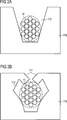
Der in
Die Kontaktierungseinrichtung
Die Klemmeinrichtung
Die Klemmeinrichtung
Durch die angegebene Ausführungsform der Kontaktierungseinrichtung
Damit die Klemmeinrichtung
Die Aussparung
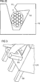
Die Kontaktierungsvorrichtung
Die
Die
Die
Beim Aufbringen des elektrischen Leiters
Der elektrische Leiter
Aufgrund der Fixierung des elektrischen Leiters in zueinander orthogonalen x- und z-Richtungen kann sich der elektrische Leiter nach einmaliger Fixierung an der Kontaktierungsvorrichtung nicht mehr von selbst lösen. Die Kontaktierungsvorrichtung ermöglicht es, insbesondere Litzendrähte beziehungsweise Lackdrähte mit einem größeren Querschnitt als der Querschnitt des Kontaktierungselements/Kontaktierungspins an der Kontaktierungseinrichtung zu fixieren. Es lassen sich beispielsweise Litzen- beziehungsweise Lackdrähte mit einem Querschnitt von 1,6 mm2 an Kontaktelementen mit einem Querschnitt von 1 mm2 fixieren. Due to the fixation of the electrical conductor in mutually orthogonal x and z directions, the electrical conductor after a single fixation on the contacting device can not solve by itself. The contacting device makes it possible in particular to fix stranded wires or enameled wires with a larger cross section than the cross section of the contacting element / contacting pin to the contacting device. It is possible, for example, to fix stranded or enamelled wires with a cross section of 1.6 mm 2 to contact elements with a cross section of 1 mm 2 .
BezugszeichenlisteLIST OF REFERENCE NUMBERS
- 11
- induktives elektrisches Bauelement inductive electrical component
- 1010
- Spulenkörper bobbins
- 1111
- elektrischer Leiter electrical conductor
- 100100
- Kontaktierungsvorrichtung contacting
- 110110
- Kontaktierungseinrichtung contacting
- 111, 112111, 112
- Klemmeinrichtung clamper
- 120120
- Kontaktierungselement/Kontaktierungspin Contacting / Kontaktierungspin
- 1111, 11121111, 1112
- Vorsprung head Start
Claims (15)
Priority Applications (6)
| Application Number | Priority Date | Filing Date | Title |
|---|---|---|---|
| DE102012103162A DE102012103162A1 (en) | 2012-04-12 | 2012-04-12 | Contacting device for connecting an electrical conductor |
| PCT/EP2013/057703 WO2013153206A1 (en) | 2012-04-12 | 2013-04-12 | Contacting device for connecting an electrical conductor |
| CN201380019249.0A CN104205501B (en) | 2012-04-12 | 2013-04-12 | Contact device for connecting electric conductor |
| JP2015504972A JP6105045B2 (en) | 2012-04-12 | 2013-04-12 | Connection device for bundled conductive wires |
| EP13717483.5A EP2837061B1 (en) | 2012-04-12 | 2013-04-12 | Contacting device for connecting an electrical conductor |
| US14/391,693 US9570818B2 (en) | 2012-04-12 | 2013-04-12 | Contacting device for connecting an electrical conductor |
Applications Claiming Priority (1)
| Application Number | Priority Date | Filing Date | Title |
|---|---|---|---|
| DE102012103162A DE102012103162A1 (en) | 2012-04-12 | 2012-04-12 | Contacting device for connecting an electrical conductor |
Publications (1)
| Publication Number | Publication Date |
|---|---|
| DE102012103162A1 true DE102012103162A1 (en) | 2013-10-17 |
Family
ID=48142765
Family Applications (1)
| Application Number | Title | Priority Date | Filing Date |
|---|---|---|---|
| DE102012103162A Withdrawn DE102012103162A1 (en) | 2012-04-12 | 2012-04-12 | Contacting device for connecting an electrical conductor |
Country Status (6)
| Country | Link |
|---|---|
| US (1) | US9570818B2 (en) |
| EP (1) | EP2837061B1 (en) |
| JP (1) | JP6105045B2 (en) |
| CN (1) | CN104205501B (en) |
| DE (1) | DE102012103162A1 (en) |
| WO (1) | WO2013153206A1 (en) |
Cited By (3)
| Publication number | Priority date | Publication date | Assignee | Title |
|---|---|---|---|---|
| DE102017121908A1 (en) * | 2017-09-21 | 2019-03-21 | Tdk Electronics Ag | Wire contact for an electrical component and method for making a strand contact |
| CN111987486A (en) * | 2019-05-23 | 2020-11-24 | 唐虞企业股份有限公司 | Wire connector |
| US11909152B2 (en) | 2017-09-21 | 2024-02-20 | Tdk Electronics Ag | Electrical device with terminal region and method for producing a terminal region |
Families Citing this family (2)
| Publication number | Priority date | Publication date | Assignee | Title |
|---|---|---|---|---|
| KR101776651B1 (en) * | 2015-09-24 | 2017-09-08 | 김명덕 | Transformer with Easy Connecting Coil |
| US11545802B2 (en) | 2020-01-16 | 2023-01-03 | Vitesco Technologies Usa, Inc. | Fork structure for positive retention and centering a wire for electrical connection |
Citations (5)
| Publication number | Priority date | Publication date | Assignee | Title |
|---|---|---|---|---|
| DE2125951A1 (en) * | 1971-05-25 | 1972-12-14 | Micafil Ag | Bobbins for the automatic application of the winding ends to solder support points on coils wound in layers |
| DE2520799A1 (en) * | 1975-05-09 | 1976-11-18 | Siemens Ag | Soldering tag with slit for circuit wires - has slit restriction at open end with width greater than metal core dia. but smaller than insulation dia. |
| DE2814009C3 (en) * | 1978-03-31 | 1981-05-27 | Siemens AG, 1000 Berlin und 8000 München | Plastic hammer brush holder with interference suppression choke |
| DE8528530U1 (en) * | 1985-10-07 | 1985-11-14 | Weiner, Norbert, Dipl.-Ing., 5275 Bergneustadt | Soldering sword especially for electrical coil bobbins |
| DE19508695B4 (en) * | 1995-03-02 | 2004-03-25 | Wago Verwaltungsgesellschaft Mbh | transformer terminal |
Family Cites Families (14)
| Publication number | Priority date | Publication date | Assignee | Title |
|---|---|---|---|---|
| JPS5584875U (en) * | 1978-12-06 | 1980-06-11 | ||
| JPS5792762A (en) * | 1980-11-29 | 1982-06-09 | Matsushita Electric Works Ltd | Pressure contact terminal |
| GB2141593B (en) | 1983-06-18 | 1986-11-26 | Yamaichi Electric Mfg | Flat cable connecting system |
| JPS6418822U (en) * | 1987-07-22 | 1989-01-30 | ||
| JPH01146466U (en) * | 1988-03-31 | 1989-10-09 | ||
| JPH0511328U (en) * | 1991-07-24 | 1993-02-12 | 矢崎総業株式会社 | Wire connection device |
| US5911593A (en) * | 1996-07-29 | 1999-06-15 | Glaser; Lawrence F. | Electrical conductor terminal and a method of connecting an electrical conductor to a terminal |
| US5759061A (en) | 1996-08-15 | 1998-06-02 | Raychem Corporation | IDC having wire slippage control |
| US6142817A (en) * | 1997-03-07 | 2000-11-07 | Marconi Communications Inc. | Insulation displacement connector |
| DE102006049966A1 (en) * | 2006-01-24 | 2007-08-02 | Hirschmann Car Communication Gmbh | Doubling in the crimping area of a plug or a coupler |
| WO2008011449A2 (en) | 2006-07-19 | 2008-01-24 | Borgwarner Inc. | Terminal weld tab having a wire squeeze limiter |
| US8454396B2 (en) * | 2006-07-19 | 2013-06-04 | Borgwarner Inc. | Terminal weld tab having a wire squeeze limiter |
| MX2009000008A (en) * | 2006-07-24 | 2009-01-23 | 3M Innovative Properties Co | Connector assembly including insulaton displacement elements configured for attachment to a printed circuit. |
| JP2010033776A (en) * | 2008-07-25 | 2010-02-12 | Sumitomo Wiring Syst Ltd | Compression terminal, splicing terminal, and pressure contact structure of electric wire |
-
2012
- 2012-04-12 DE DE102012103162A patent/DE102012103162A1/en not_active Withdrawn
-
2013
- 2013-04-12 US US14/391,693 patent/US9570818B2/en active Active
- 2013-04-12 EP EP13717483.5A patent/EP2837061B1/en active Active
- 2013-04-12 CN CN201380019249.0A patent/CN104205501B/en active Active
- 2013-04-12 JP JP2015504972A patent/JP6105045B2/en active Active
- 2013-04-12 WO PCT/EP2013/057703 patent/WO2013153206A1/en active Application Filing
Patent Citations (5)
| Publication number | Priority date | Publication date | Assignee | Title |
|---|---|---|---|---|
| DE2125951A1 (en) * | 1971-05-25 | 1972-12-14 | Micafil Ag | Bobbins for the automatic application of the winding ends to solder support points on coils wound in layers |
| DE2520799A1 (en) * | 1975-05-09 | 1976-11-18 | Siemens Ag | Soldering tag with slit for circuit wires - has slit restriction at open end with width greater than metal core dia. but smaller than insulation dia. |
| DE2814009C3 (en) * | 1978-03-31 | 1981-05-27 | Siemens AG, 1000 Berlin und 8000 München | Plastic hammer brush holder with interference suppression choke |
| DE8528530U1 (en) * | 1985-10-07 | 1985-11-14 | Weiner, Norbert, Dipl.-Ing., 5275 Bergneustadt | Soldering sword especially for electrical coil bobbins |
| DE19508695B4 (en) * | 1995-03-02 | 2004-03-25 | Wago Verwaltungsgesellschaft Mbh | transformer terminal |
Cited By (7)
| Publication number | Priority date | Publication date | Assignee | Title |
|---|---|---|---|---|
| DE102017121908A1 (en) * | 2017-09-21 | 2019-03-21 | Tdk Electronics Ag | Wire contact for an electrical component and method for making a strand contact |
| CN111133638A (en) * | 2017-09-21 | 2020-05-08 | Tdk电子股份有限公司 | Stranded wire contact mechanism for electric device and method for manufacturing stranded wire contact mechanism |
| CN111133638B (en) * | 2017-09-21 | 2022-07-29 | Tdk电子股份有限公司 | Electrical component and method for producing a strand contact arrangement of an electrical component |
| US11600433B2 (en) | 2017-09-21 | 2023-03-07 | Tdk Electronics Ag | Stranded wire contact for an electrical device and method for producing a stranded wire contact |
| DE102017121908B4 (en) | 2017-09-21 | 2023-12-07 | Tdk Electronics Ag | Electrical component with stranded contact and method for producing a stranded contact |
| US11909152B2 (en) | 2017-09-21 | 2024-02-20 | Tdk Electronics Ag | Electrical device with terminal region and method for producing a terminal region |
| CN111987486A (en) * | 2019-05-23 | 2020-11-24 | 唐虞企业股份有限公司 | Wire connector |
Also Published As
| Publication number | Publication date |
|---|---|
| JP2015515730A (en) | 2015-05-28 |
| CN104205501B (en) | 2017-10-24 |
| EP2837061B1 (en) | 2021-07-07 |
| EP2837061A1 (en) | 2015-02-18 |
| WO2013153206A1 (en) | 2013-10-17 |
| JP6105045B2 (en) | 2017-03-29 |
| CN104205501A (en) | 2014-12-10 |
| US9570818B2 (en) | 2017-02-14 |
| US20150145633A1 (en) | 2015-05-28 |
Similar Documents
| Publication | Publication Date | Title |
|---|---|---|
| DE102006008056B4 (en) | Earthing plate and tool for mounting a coaxial cable to the same | |
| EP3025396B1 (en) | Terminal for contacting an electric conductor | |
| EP1774545B1 (en) | Holder for electric components | |
| DE10128395B4 (en) | Spool for transformer or current transformer | |
| DE102012103162A1 (en) | Contacting device for connecting an electrical conductor | |
| DE102013005399A1 (en) | Motor structure with connector or terminal block to which a conductive sealed terminal is soldered " | |
| DE3717806A1 (en) | CONNECTING TERMINAL | |
| DE102019210869A1 (en) | Discrete electrical component and compliant pin structure for a pinless discrete electrical component | |
| DE102015104794A1 (en) | Inductive component and method for producing an inductive component | |
| DE102014005118A1 (en) | suppression choke | |
| EP3602582B1 (en) | Electrical component, component arrangement and method for producing a component arrangement | |
| EP0124860B1 (en) | Coil bobbin | |
| DE102004049575B4 (en) | Electrical connection element and method for connecting a conductor cable | |
| DE2953859C2 (en) | Tapping element for electric heating devices | |
| EP1598839B1 (en) | Translator for high frequency device arranged directly on a circuit board | |
| EP0355378A2 (en) | Test clip for SMD circuits and its method of fabrication | |
| DE2046488C3 (en) | Electrical connector | |
| DE2606683A1 (en) | Low current fine wire twisted cables - have terminals formed out of cable material to reduce costs | |
| DE202013006633U1 (en) | Terminal for contacting an electrical conductor | |
| DE2509427C3 (en) | ||
| EP4340553A1 (en) | Electronic module with integrated circuit board holder for contacting at least one wire with a circuit board that can be arranged in the circuit board holder, and associated method | |
| DE4129990A1 (en) | Connection foot for SMD e.g. switch, transformer or coil - has opposing connection tag for lead wire and bent connection finger | |
| DE1936422C (en) | Electrical through conductor for a circuit board | |
| DE2726868C3 (en) | Method for attaching metallic connections to bodies of electrical components | |
| EP2161786A1 (en) | Cable connection element |
Legal Events
| Date | Code | Title | Description |
|---|---|---|---|
| R012 | Request for examination validly filed | ||
| R081 | Change of applicant/patentee |
Owner name: TDK ELECTRONICS AG, DE Free format text: FORMER OWNER: EPCOS AG, 81669 MUENCHEN, DE |
|
| R082 | Change of representative |
Representative=s name: EPPING HERMANN FISCHER PATENTANWALTSGESELLSCHA, DE |
|
| R120 | Application withdrawn or ip right abandoned |