DE102010009291A1 - Method and apparatus for an anatomy-adapted pseudo-holographic display - Google Patents
Method and apparatus for an anatomy-adapted pseudo-holographic display Download PDFInfo
- Publication number
- DE102010009291A1 DE102010009291A1 DE102010009291A DE102010009291A DE102010009291A1 DE 102010009291 A1 DE102010009291 A1 DE 102010009291A1 DE 102010009291 A DE102010009291 A DE 102010009291A DE 102010009291 A DE102010009291 A DE 102010009291A DE 102010009291 A1 DE102010009291 A1 DE 102010009291A1
- Authority
- DE
- Germany
- Prior art keywords
- image
- display
- pixel
- perspective
- subpixels
- Prior art date
- Legal status (The legal status is an assumption and is not a legal conclusion. Google has not performed a legal analysis and makes no representation as to the accuracy of the status listed.)
- Ceased
Links
Images


Classifications
-
- H—ELECTRICITY
- H04—ELECTRIC COMMUNICATION TECHNIQUE
- H04N—PICTORIAL COMMUNICATION, e.g. TELEVISION
- H04N13/00—Stereoscopic video systems; Multi-view video systems; Details thereof
- H04N13/30—Image reproducers
- H04N13/302—Image reproducers for viewing without the aid of special glasses, i.e. using autostereoscopic displays
-
- H—ELECTRICITY
- H04—ELECTRIC COMMUNICATION TECHNIQUE
- H04N—PICTORIAL COMMUNICATION, e.g. TELEVISION
- H04N13/00—Stereoscopic video systems; Multi-view video systems; Details thereof
- H04N13/30—Image reproducers
- H04N13/349—Multi-view displays for displaying three or more geometrical viewpoints without viewer tracking
-
- H—ELECTRICITY
- H04—ELECTRIC COMMUNICATION TECHNIQUE
- H04N—PICTORIAL COMMUNICATION, e.g. TELEVISION
- H04N13/00—Stereoscopic video systems; Multi-view video systems; Details thereof
- H04N13/20—Image signal generators
- H04N13/261—Image signal generators with monoscopic-to-stereoscopic image conversion
-
- G—PHYSICS
- G06—COMPUTING; CALCULATING OR COUNTING
- G06T—IMAGE DATA PROCESSING OR GENERATION, IN GENERAL
- G06T15/00—3D [Three Dimensional] image rendering
- G06T15/50—Lighting effects
-
- G—PHYSICS
- G06—COMPUTING; CALCULATING OR COUNTING
- G06T—IMAGE DATA PROCESSING OR GENERATION, IN GENERAL
- G06T19/00—Manipulating 3D models or images for computer graphics
- G06T19/20—Editing of 3D images, e.g. changing shapes or colours, aligning objects or positioning parts
-
- G—PHYSICS
- G09—EDUCATION; CRYPTOGRAPHY; DISPLAY; ADVERTISING; SEALS
- G09G—ARRANGEMENTS OR CIRCUITS FOR CONTROL OF INDICATING DEVICES USING STATIC MEANS TO PRESENT VARIABLE INFORMATION
- G09G3/00—Control arrangements or circuits, of interest only in connection with visual indicators other than cathode-ray tubes
- G09G3/001—Control arrangements or circuits, of interest only in connection with visual indicators other than cathode-ray tubes using specific devices not provided for in groups G09G3/02 - G09G3/36, e.g. using an intermediate record carrier such as a film slide; Projection systems; Display of non-alphanumerical information, solely or in combination with alphanumerical information, e.g. digital display on projected diapositive as background
- G09G3/003—Control arrangements or circuits, of interest only in connection with visual indicators other than cathode-ray tubes using specific devices not provided for in groups G09G3/02 - G09G3/36, e.g. using an intermediate record carrier such as a film slide; Projection systems; Display of non-alphanumerical information, solely or in combination with alphanumerical information, e.g. digital display on projected diapositive as background to produce spatial visual effects
-
- H—ELECTRICITY
- H04—ELECTRIC COMMUNICATION TECHNIQUE
- H04N—PICTORIAL COMMUNICATION, e.g. TELEVISION
- H04N13/00—Stereoscopic video systems; Multi-view video systems; Details thereof
- H04N13/10—Processing, recording or transmission of stereoscopic or multi-view image signals
- H04N13/106—Processing image signals
- H04N13/111—Transformation of image signals corresponding to virtual viewpoints, e.g. spatial image interpolation
-
- H—ELECTRICITY
- H04—ELECTRIC COMMUNICATION TECHNIQUE
- H04N—PICTORIAL COMMUNICATION, e.g. TELEVISION
- H04N13/00—Stereoscopic video systems; Multi-view video systems; Details thereof
- H04N13/10—Processing, recording or transmission of stereoscopic or multi-view image signals
- H04N13/106—Processing image signals
- H04N13/172—Processing image signals image signals comprising non-image signal components, e.g. headers or format information
- H04N13/183—On-screen display [OSD] information, e.g. subtitles or menus
-
- H—ELECTRICITY
- H04—ELECTRIC COMMUNICATION TECHNIQUE
- H04N—PICTORIAL COMMUNICATION, e.g. TELEVISION
- H04N13/00—Stereoscopic video systems; Multi-view video systems; Details thereof
- H04N13/30—Image reproducers
- H04N13/302—Image reproducers for viewing without the aid of special glasses, i.e. using autostereoscopic displays
- H04N13/305—Image reproducers for viewing without the aid of special glasses, i.e. using autostereoscopic displays using lenticular lenses, e.g. arrangements of cylindrical lenses
-
- H—ELECTRICITY
- H04—ELECTRIC COMMUNICATION TECHNIQUE
- H04N—PICTORIAL COMMUNICATION, e.g. TELEVISION
- H04N13/00—Stereoscopic video systems; Multi-view video systems; Details thereof
- H04N13/30—Image reproducers
- H04N13/302—Image reproducers for viewing without the aid of special glasses, i.e. using autostereoscopic displays
- H04N13/31—Image reproducers for viewing without the aid of special glasses, i.e. using autostereoscopic displays using parallax barriers
-
- H—ELECTRICITY
- H04—ELECTRIC COMMUNICATION TECHNIQUE
- H04N—PICTORIAL COMMUNICATION, e.g. TELEVISION
- H04N13/00—Stereoscopic video systems; Multi-view video systems; Details thereof
- H04N13/30—Image reproducers
- H04N13/324—Colour aspects
-
- H—ELECTRICITY
- H04—ELECTRIC COMMUNICATION TECHNIQUE
- H04N—PICTORIAL COMMUNICATION, e.g. TELEVISION
- H04N13/00—Stereoscopic video systems; Multi-view video systems; Details thereof
- H04N13/30—Image reproducers
- H04N13/366—Image reproducers using viewer tracking
- H04N13/383—Image reproducers using viewer tracking for tracking with gaze detection, i.e. detecting the lines of sight of the viewer's eyes
-
- H—ELECTRICITY
- H04—ELECTRIC COMMUNICATION TECHNIQUE
- H04N—PICTORIAL COMMUNICATION, e.g. TELEVISION
- H04N13/00—Stereoscopic video systems; Multi-view video systems; Details thereof
- H04N13/30—Image reproducers
- H04N13/398—Synchronisation thereof; Control thereof
-
- G—PHYSICS
- G06—COMPUTING; CALCULATING OR COUNTING
- G06T—IMAGE DATA PROCESSING OR GENERATION, IN GENERAL
- G06T2219/00—Indexing scheme for manipulating 3D models or images for computer graphics
- G06T2219/20—Indexing scheme for editing of 3D models
- G06T2219/2012—Colour editing, changing, or manipulating; Use of colour codes
-
- G—PHYSICS
- G09—EDUCATION; CRYPTOGRAPHY; DISPLAY; ADVERTISING; SEALS
- G09G—ARRANGEMENTS OR CIRCUITS FOR CONTROL OF INDICATING DEVICES USING STATIC MEANS TO PRESENT VARIABLE INFORMATION
- G09G2300/00—Aspects of the constitution of display devices
- G09G2300/04—Structural and physical details of display devices
- G09G2300/0439—Pixel structures
- G09G2300/0452—Details of colour pixel setup, e.g. pixel composed of a red, a blue and two green components
-
- Y—GENERAL TAGGING OF NEW TECHNOLOGICAL DEVELOPMENTS; GENERAL TAGGING OF CROSS-SECTIONAL TECHNOLOGIES SPANNING OVER SEVERAL SECTIONS OF THE IPC; TECHNICAL SUBJECTS COVERED BY FORMER USPC CROSS-REFERENCE ART COLLECTIONS [XRACs] AND DIGESTS
- Y10—TECHNICAL SUBJECTS COVERED BY FORMER USPC
- Y10T—TECHNICAL SUBJECTS COVERED BY FORMER US CLASSIFICATION
- Y10T29/00—Metal working
- Y10T29/49—Method of mechanical manufacture
- Y10T29/49002—Electrical device making
- Y10T29/49004—Electrical device making including measuring or testing of device or component part
Abstract
Technisches Problem Ein perfekter 3D-Fernseher muss es ermöglichen, dass keine 3D-Brille getragen werden muss, dass man aus allen Richtungen und Entfernungen 3D sehen kann, dass das 3D-Bild qualitativ genau so gut ist wie das 2D-Bild und dass man ihn auch für 2D-Inhalte mit gleicher Qualität verwenden kann. Lösung des Problems Die hier beschriebene Offenlegung erfüllt diese Anforderungen. Sie beinhaltet Verfahren und Vorrichtungen für ein autostereoskopischen Displays, welches sich durch folgende Eigenschaften vom bisherigen Stand der Technik unterscheidet: 1. Neben den RGB-Subpixeln enthält es auch Hell/Dunkel-Subpixel, in welchen z. B. Kantenmerkmale dargestellt werden, um die Raumbilderzeugung im Gehirn zu erleichtern. 2. Die Aufteilung von Pixeln in Subpixel wird fallengelassen. Statt dessen gibt es nur noch eine wesentlich größere Anzahl von farbigen Pixeln, welche in horizontaler und vertikaler Richtung die gleiche Ausdehnung besitzen. 3. Die wesentlich größere Anzahl von farbigen Pixel wird zur gleichzeitigen Darstellung von wesentlich mehr Perspektiven genutzt, die so erzeugt werden, dass nur diejenigen Pixel einer Perspektive erzeugt werden, welche auch auf dem Display angezeigt werden. 4. Die Erzeugung der Vielzahl von Perspektiven wird dadurch ermöglicht, dass für jeder Zeile des Displays eine eigene Zeilenrecheneinheit vorhanden ist. 5. Bei der Herstellung des Displays werden die farbigen Pixel, gesteuert durch einen optischen Sensor, direkt auf dem optischen Element, z. B. einer Lentikularstruktur, aufgebracht. Dadurch lässt sich eine wesentlich höhere Qualität erreichen. Anwendungsgebiete 3D-Fernsehen, 3D-MonitoreTechnical problem A perfect 3D television must make it possible that no 3D glasses have to be worn, that 3D can be seen from all directions and distances, that the 3D image is of the same quality as the 2D image and that it can be viewed can also be used for 2D content of the same quality. Solution to the problem The disclosure described here meets these requirements. It contains methods and devices for an autostereoscopic display, which differs from the prior art by the following properties: 1. In addition to the RGB subpixels, it also contains light / dark subpixels, in which, for. B. edge features are shown to facilitate spatial imaging in the brain. 2. The division of pixels into subpixels is dropped. Instead, there is only a much larger number of colored pixels, which have the same dimensions in the horizontal and vertical directions. 3. The significantly larger number of colored pixels is used for the simultaneous display of significantly more perspectives, which are generated in such a way that only those pixels of a perspective are generated which are also shown on the display. 4. The generation of the multitude of perspectives is made possible by the fact that a separate line arithmetic unit is provided for each line of the display. 5. In the manufacture of the display, the colored pixels, controlled by an optical sensor, directly on the optical element, for. B. a lenticular structure applied. This enables a much higher quality to be achieved. Areas of application 3D television, 3D monitors
Description
Die Erfindung betrifft Verfahren und Vorrichtungen für ein autostereoskopisches Display, auf welchem aus einem zugeführten Stereobild in einem beliebigen 3D-Format eine Vielzahl von Perspektiven, im allgemeinen mehr als 100, verkämmt auf einem Display angezeigt werden, welches aus einem optischen Element und einer bilderzeugenden Einheit besteht. Die Vielzahl von Perspektiven wird in der Weise erzeugt, dass immer nur diejenigen Pixel einer Perspektive erzeugt werden, welche auch angezeigt werden müssen. Die bilderzeugende Einheit des Displays besteht aus Pixeln/Subpixeln, welche entweder eine Farbe, z. B. Rot, Grün oder Blau, abstrahlen, oder aus Pixeln/Subpixeln, welche zur Verbesserung des Raumbildeindruckes des Betrachters auch Kanteninformation anzeigen.The invention relates to methods and apparatuses for an autostereoscopic display, on which a plurality of perspectives, generally more than 100, of a supplied stereo image in any 3D format are displayed on a display, which consists of an optical element and an image-forming unit consists. The multitude of perspectives is generated in such a way that only those pixels of a perspective are generated, which also have to be displayed. The imaging unit of the display consists of pixels / subpixels which are either a color, e.g. As red, green or blue, radiate, or from pixels / subpixels, which also display edge information to improve the spatial image impression of the viewer.
Die Vorstellung, welche Eigenschaften ein perfekter 3D-Fernseher haben sollte, haben sich in den letzten Jahren stark konkretisiert. Dazu gehören z. B. die Anforderung, dass man keine 3D-Brille tragen muss, dass man aus allen Richtungen und Entfernungen 3D sehen kann, dass das 3D-Bild qualitativ genau so gut ist wie das 2D-Bild und dass man ihn auch für 2D-Inhalte mit gleicher Qualität verwenden kann. Diese Anforderungen sollen mit den hier vorgestellten Verfahren und Vorrichtungen vollständig erfüllt werden.The idea of what qualities a perfect 3D television should have has become more concrete in recent years. These include z. For example, the requirement that you do not have to wear 3D glasses, that you can see from all directions and distances 3D, that the 3D image is just as good in quality as the 2D image and that you also use it for 2D content can use the same quality. These requirements are to be fully met with the methods and devices presented here.
Das dieser Anmeldung zu Grunde liegende Display ist in der Lage ein 3D-Bild oder eine 3D-Bildfolge in jedem Format, wie z. B. einem Stereobild oder einer Stereobildfolge, zu empfangen. Andere Format, wie z. B. Stereobild inklusive einer Disparitätskarte, können ebenso empfangen und verarbeitet werden.The underlying this application display is capable of a 3D image or a 3D image sequence in any format, such. B. a stereo image or a stereo image sequence to receive. Other format, such as. B. stereo image including a disparity card can also be received and processed.
Ein solch empfangenes Stereobild wird zunächst rektifiziert, d. h. auf Stereo-Normalform, gebracht. Ist dies schon der Fall, so ergibt sich hier die identische Abbildung.Such a received stereo image is first rectified, i. H. on stereo normal form, brought. If this is already the case, then the identical figure arises here.
Sodann werden aus den beiden Bildern verschiedene Merkmale, wie z. B. Kanten oder markante Bildpunkte (SURF) identifiziert. Verschiedene Merkmale können hier extrahiert werden. Eine besondere Einschränkung ist nicht gegeben. Diese Merkmale werden sowohl für die Berechnung der Disparitätskarte, falls dies erforderlich ist, als auch für die Visualisierung in bestimmten zusätzlichen Subpixeln verwendet. Dies ist die erste der dieser Anmeldung zu Grunde liegenden neuen Eigenschaft.Then, from the two pictures different features, such. B. edges or prominent pixels (SURF) identified. Various features can be extracted here. A special restriction is not given. These features are used both for calculating the disparity map, if required, and for visualization in certain additional subpixels. This is the first of the new properties underlying this application.
Wurde die Disparitätskarte bereits mit empfangen, so wird der nächste Schritt übersprungen. Im anderen Fall wird die Disparitätskarte des Stereobildes berechnet. Sie enthält eine Zuordnung der linken und rechten Pixel, welche in beiden empfangenen Perspektiven vorhanden sind. Gleichzeitig werden die Links- und Rechtsverdeckungen identifiziert.If the disparity card has already been received, the next step is skipped. Otherwise, the disparity map of the stereo image is calculated. It contains an association of the left and right pixels that are present in both received perspectives. At the same time, the left and right occlusions are identified.
Mithilfe der Disparitätskarte des empfangenen Stereobildes und der Merkmale werden sodann beliebig viele Perspektiven synthetisiert. Dabei wird so vorgegangen, dass immer nur diejenigen Subpixel synthetisiert werden, welche auf dem Display auch tatsächlich angezeigt werden müssen. Dies gilt in gleicher Weise auch für die vorher beschriebenen Merkmale, welche in besonderen Subpixeln angezeigt werden. Das bedeutet, dass bei 100 anzuzeigenden Perspektiven aus jeder Perspektive nur 1% der Subpixel berechnet werden.Using the disparity map of the received stereo image and the features then any number of perspectives are synthesized. This is done so that only those subpixels are synthesized, which must be displayed on the display actually. This applies equally to the previously described features, which are displayed in special subpixels. This means that for every 100 perspectives to be displayed, only 1% of the subpixels are calculated from each perspective.
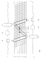
Die Information, welche Perspektive auf welchem Subpixel angezeigt werden soll, ist in der Perspektivenkarte P festgelegt. Diese wird bei der Produktion des Displays durch einen Kalibrierungsprozess zwischen Subpixeln und optischen System festgelegt und abgespeichert. Benachbarte Subpixel sind im Allgemeinen unterschiedlichen Perspektiven zugeordnet. Die Speicherung der verschiedenen Subpixel aus den unterschiedlichen Perspektiven im pseudoholographischen Bild B soll im folgenden zur Vereinfachung der Beschreibung als „Verkämmung” bezeichnet werden.The information about which perspective is to be displayed on which subpixel is defined in the perspective map P. This is determined and stored in the production of the display by a calibration process between subpixels and optical system. Adjacent subpixels are generally associated with different perspectives. The storage of the various subpixels from the different perspectives in the pseudo-holographic image B will be referred to as "merging" in the following to simplify the description.
Das Display selbst ist charakterisiert durch ein Panel von Subpixeln und einem vorgeschalteten optischen Element. Die Subpixel können sowohl Farbsubpixel wie z. B. RGB oder CMY als auch Hell/Dunkel-Subpixel sein. In den Farbsubpixeln wird die Farbinformation der Subpixel der darzustellenden Perspektiven angezeigt. Die Hell/Dunkel-Subpixel enthalten z. B. als Grauwerte den 3D-Eindruck unterstützende Bildmerkmale. Dieses Konzept berücksichtigt die Tatsache, dass das menschliche Auge ca. 110 Mio. Hell/Dunkel-Rezeptoren und nur ca. 6.5 Mio. Farbrezeptoren besitzt. Ebenfalls bekannt ist die Tatsache, dass das menschliche Gehirn zu einem wesentlichen Teil Kanten an Objekten dazu verwendet, um im Gehirn das dreidimensionale Raumbild aufzubauen. Werden also über Hell/Dunkel-Subpixel Kanteninformationen angezeigt, so wird diese Bildinformation über die viel größere Anzahl der Hell/Dunkel-Rezeptoren aufgenommen. Die Arbeit des Gehirns wird dadurch erleichtert. Das hier vorgestellte Display ist daher an die Anatomie des Auges und die nachgeschaltete Informationsverarbeitung besser angepasst. Dies ist die zweite dieser Anmeldung zu Grunde liegende neue Eigenschaft.The display itself is characterized by a panel of subpixels and an upstream optical element. The subpixels can be both color subpixels such. B. RGB or CMY and bright / dark subpixels. In the color subpixels, the color information of the subpixels of the perspectives to be displayed is displayed. The light / dark subpixels contain z. B. as gray scale the 3D impression supporting image features. This concept takes into account the fact that the human eye has about 110 million light / dark receptors and only about 6.5 million color receptors. Also known is the fact that the human brain essentially uses edges on objects to build up the three-dimensional space image in the brain. Thus, if edge information is displayed via light / dark subpixels, this image information is recorded on the much larger number of light / dark receptors. The work of the brain is thereby facilitated. The display presented here is therefore better adapted to the anatomy of the eye and the downstream information processing. This is the second new property underlying this application.
Zur Verbesserung der Qualität des Bildes wird zusätzlich die Anzahl der angezeigten Subpixel wesentlich erhöht. Ein pseudoholographisches Display dieser Patentanmeldung besitzt mindestens 10 bis 20 mal so viele Subpixel wie im empfangenen Stereobild vorhanden sind. Diese größere Anzahl der Subpixel ermöglicht es, aus den vielen Perspektiven, die synthetisiert werden, eine größere Anzahl von Pixeln pro Perspektive darzustellen. High-Definition-Bilder und -Videos der heutigen Generation besitzen i. A. 1920×1080 Pixel mit 5760 Subpixel pro Zeile. Bei einer Verzehnfachung und unter Berücksichtigung derjenigen Subpixel, welche Merkmalsinformationen anzeigen, besitzt ein Display der hier vorgestellten Patentanmeldung also mindestens 76.800×1080 Subpixel. Dabei wird berücksichtigt, dass bei den autostereoskopischen Displays die Zuordnung der Perspektiven auf Subpixel-Ebene geschieht. Eine Zusammenfassung zu Pixeln ist dort nicht relevant. Die Anforderung, dass alle Subpixel eines Pixels zusammen ein Quadrat bilden, wird in der hier vorliegenden Patentanmeldung fallen gelassen. Vielmehr ist jeder Subpixel ein eigenständiges Element. Jeder dieser Subpixel besitzt eine Farbe des gewählten Farbsystems und besitzt in horizontaler und vertikaler Richtung die gleiche Ausdehnung. Dies ist die dritte dieser Anmeldung zu Grunde liegende neue Eigenschaft. Mit der heutigen Displaytechnologie der OLED- oder Nano-Technologie ist dies technisch problemlos realisierbar. In addition, to improve the quality of the image, the number of displayed subpixels is substantially increased. A pseudoholographic display of this patent application has at least 10 to 20 times as many subpixels as are present in the received stereo image. This greater number of subpixels makes it possible to represent a larger number of pixels per perspective out of the many perspectives that are synthesized. Hi-definition images and videos of today's generation i own. A. 1920 × 1080 pixels with 5760 subpixels per line. At a tenfold and taking into account those subpixels indicating feature information, a display of the patent application presented here thus has at least 76,800 × 1080 subpixels. It is taken into account that in autostereoscopic displays, the assignment of perspectives is done at the subpixel level. A summary of pixels is not relevant there. The requirement that all subpixels of a pixel together form a square is dropped in the present patent application. Rather, each subpixel is an independent element. Each of these subpixels has a color of the selected color system and has the same extent in the horizontal and vertical directions. This is the third new property underlying this application. With today's display technology of OLED or nano technology, this is technically easy to implement.
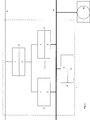
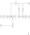
Da die bisher vorgestellten Verfahrensschritte der Rektifizierung, Disparitätsberechnung und Perspektivensynthese in Echtzeit durchgeführt werden müssen, ist eine angemessene Verarbeitungskapazität erforderlich. Diese wird dadurch sichergestellt, dass eine Vielzahl von Recheneinheiten Bestandteil des Displays sind. Jeder sogenannten Zeilenrecheneinheit ist eine eigene kleine Anzahl von Zeilen des Displays zugeordnet. Im Extremfall, der hier nicht ausgeschlossen und durchaus realistisch ist, wird jeder Zeilenrecheneinheit eine eigene Zeile des Displays zugeordnet.Since the process steps of rectification, disparity calculation and perspective synthesis presented so far must be performed in real time, adequate processing capacity is required. This is ensured by the fact that a large number of computing units are part of the display. Each so-called row calculation unit is assigned its own small number of lines of the display. In the extreme case, which is not excluded here and quite realistic, each row calculation unit is assigned a separate line of the display.
Alle Verfahrensschritte sind so implementiert, dass sie zeilenweise unabhängig von einander und parallel durchgeführt werden können.All process steps are implemented so that they can be performed line by line independently of each other and in parallel.
Besitzt das Display also beispielsweise 1080 Zeilen, was dem heutigen HD-Format entspricht, so besitzt die Recheneinheit 1080 Zeilenrecheneinheiten. Alle Recheneinheiten verfügen über lokalen Speicher zur Durchführung ihrer Operationen und können parallel auf einen globalen Speicher zugreifen. Eine Kontrolleinheit sorgt für die Synchronisation der einzelnen Verarbeitungsschritte. Diese Architektur ist die vierte dieser Anmeldung zu Grunde liegende neue Eigenschaft.For example, if the display has 1080 lines, which corresponds to today's HD format, the processing unit has 1080 line calculation units. All processors have local memory to perform their operations and can access a global memory in parallel. A control unit ensures the synchronization of the individual processing steps. This architecture is the fourth underlying feature of this application.
Die Herstellung dieses autostereoskopischen Displays wird so durchgeführt, dass das bildgebende Panel direkt auf der Rückseite des optischen Elements aufgebracht wird. Dabei erkennt ein optisches Sensorelement die exakte Lage der Linsen bzw. Barrieren. Diese Information wird sodann zur Steuerung des Aufbringungsprozesses der bildgebenden Subpixel verwendet. Dies ist die fünfte dieser Anmeldung zu Grunde liegende neue Eigenschaft.The production of this autostereoscopic display is performed so that the imaging panel is applied directly to the back of the optical element. In this case, an optical sensor element detects the exact position of the lenses or barriers. This information is then used to control the deposition process of the imaging subpixels. This is the fifth new property underlying this application.
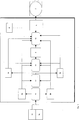
Ein Blockdiagramm des Gesamtsystems ist in
Stand der TechnikState of the art
Verfahren der Rektifizierung sind in der Literatur weitläufig bekannt und haben bereits ihren Einzug in die Standardliteratur der Stereobildverarbeitung gefunden [7]. Sie brauchen hier nicht detailliert erwähnt zu werden. Eine Hardware-Implementierung ist in [8] beschrieben.Methods of rectification are widely known in the literature and have already found their way into the standard literature of stereo image processing [7]. You do not need to be mentioned here in detail. A hardware implementation is described in [8].
Auch die Merkmalextraktion, wie z. B. SURF- oder Kanten-Operatoren, sind in jedem Buch der digitalen Bildverarbeitung dargestellt 31]The feature extraction, such. As SURF or edge operators, are presented in each book of digital image processing 31]
Verfahren der Disparitätsschätzung sind z. B. in [2], [4] und [6] beschrieben. Wichtig ist der Unterschied zwischen iterativen Verfahren und Verfahren, welche die lineare Programmierung als Basis verwenden. In letzterem Fall wird i. A. eine Monotonie der Zuordnung vorausgesetzt. Dies bedeutet:
In einer beliebigen Szene, wie sie aus dramaturgischen Gründen aber möglicherweise erforderlich ist, kann diese Voraussetzung jedoch nicht immer erfüllt sein. Ein schmales Objekt im Vordergrund kann leicht zu einer „Inversion” der Zuordnung in der Disparitätskarte führen. Daher soll in der vorgelegten Offenlegung diese Voraussetzung fallen gelassen werden.However, in any scene that may be required for dramaturgical reasons, this requirement may not always be met. A narrow object in the foreground can easily lead to an "inversion" of the mapping in the disparity map. Therefore, this requirement should be dropped in the submitted disclosure.
Das hier vorgestellte Verfahren soll jedoch nicht auf den Farb- oder Grauwerten der Pixel beruhen. Vielmehr wird jeder Pixel zur Sicherung der Zuordnung um die vorher berechneten Merkmalswerte erweitert. Eine Disparitätsschätzung, bei der jeder Pixel einen Merkmalsvektor darstellt, ist das Ergebnis. However, the method presented here should not be based on the color or gray values of the pixels. Rather, each pixel is extended by the previously calculated feature values to secure the assignment. A disparity estimate in which each pixel represents a feature vector is the result.
Die pseudoholographische Bildsynthese ist schon im
Hardware-Architekturen von autostereoskopischen Displays, bei denen neben den Farbwerten RGB oder CMY, auch Merkmale wie Kanten oder markante Punkte visualisiert werden, um die Erkennung der Räumlichkeit durch das menschliche Gehirn zu erleichtern, sind in der Literatur bisher nicht beschrieben.Hardware architectures of autostereoscopic displays, in which besides the color values RGB or CMY, also features such as edges or prominent points are visualized to facilitate the recognition of the spatiality by the human brain are not described in the literature so far.
Ebenso sind Architekturen von autostereoskopischen Displays, bei denen jede Zeile oder sogar jeder einzelne Subpixel über eine eigene Recheneinheit verfügt, in der Literatur bisher nicht beschrieben.Likewise, architectures of autostereoscopic displays in which each line or even each individual subpixel has its own arithmetic unit have not previously been described in the literature.
BezugszeichenlisteLIST OF REFERENCE NUMBERS
Fig. 1: Blockdiagramm des Gesamtsystems
- 1a
- Empfanges linkes Teilbild Il,
- 1b
- Empfanges rechtes Teilbild Ir,
- 2a
- Rektifiziertes linkes Teilbild Rl,
- 2b
- Rektifiziertes rechtes Teilbild Rr,
- 3a
- Matrix Ml der pro
Pixel berechneten Merkmale 1...K des linkes Teilbildes, - 3b
- Matrix Mr der pro
Pixel berechneten Merkmale 1...K des rechten Teilbildes, - 4
- Disparitätskarte D,
- 5
- Pseudoholographisch verkämmtes Bild B mit M verkämmten Perspektiven,
- 6
- Perspektivenkarte P,
- 7
- Autostereoskopisches Display,
- 11
- Bilder rektifizieren und in
2a und 2b ablegen, - 12
- Merkmale extrahieren und in
3a und 3b ablegen, - 13
- Disparitätskarte berechnen, falls nicht zugeführt, und in
4 ablegen, - 14
- Pseudoholographisches Bild B der verkämmten Perspektiven erzeugen und in
5 ablegen.
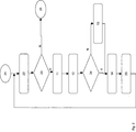
- 11
- Bilder rektifizieren,
- 12
- Merkmale extrahieren,
- 13
- Disparitätskarte erstellen,
- 14
- Pseudoholographische Perspektiven synthetisieren,
- 21
- Start,
- 22
- Bilder einlesen,
- 23
- Bilder eingelesen?,
- 24
- Disparitätskarte vorhanden?,
- 25
- Pseudoholographisches Bild auf Display ausgeben,
- 26
- Stop.
- 1
- Prozessor,
- 2
- Lokaler Speicher,
- 3
Zeilenrecheneinheit 1,- 4
- Zeilenrecheneinheit n,
- 5
- Kontrolleinheit,
- 6
- Globale Speichereinheit,
- 7
- Single-Chip-Implementierung,
- 8
- Steuerbus,
- 9
- Datenbus,
- 10
- Autostereoskopisches Display.
- A
- Altes Subpixel-Layout,
- N
- Neues Subpixel-Layout,
- R
- Rot,
- G
- Grün,
- B
- Blau,
- W
- Weiß
- 1–36
- Nummer der anzuzeigenden Perspektive in diesem Subpixel.
- 1
- Linke Szene,
- 2
- Zeile einer Disparitätskarte,
- 3
- Linkes Teilbild,
- 4
Zwischenperspektive 1,- 5
Zwischenperspektive 2,- 6
Zwischenperspektive 3,- 7
Zwischenperspektive 4,- 8
Zwischenperspektive 5,- 9
Zwischenperspektive 6,- 10
- Rechtes Teilbild,
- 11
- Rechte Szene,
- 12
- Rechtsverdeckung im linken Teilbild,
- 13
- Linksverdeckung im rechten Teilbild.
- 1
- Linke Szene,
- 2a
- Rechtsverdeckung des vorderen Objektes im linken Teilbild,
- 2b
- Hinteres Objekt,
- 2c
- Vorderes Objekt,
- 2d
- Linksverdeckung des vorderen Objektes im rechten Teilbild
- 3
- Linkes Teilbild,
- 4
Zwischenperspektive 1,- 5
Zwischenperspektive 2,- 6
Zwischenperspektive 3,- 7
Zwischenperspektive 4,- 8
Zwischenperspektive 5,- 9
Zwischenperspektive 6,- 10
- Rechtes Teilbild,
- 11
- Rechte Szene,
- 12
- Rechtsverdeckung im linken Teilbild,
- 13
- Linksverdeckung im rechten Teilbild,
- 14a
- Cross-over-Bildsegment C1 im linken Teilbild,
- 14b
- Cross-over-Bildsegment C1 im rechten Teilbild,
- P1
- jr/3 liegt links von jrmin_PositionNeu,
- P2
- jr/3 liegt zwischen jrmin_PositionNeu und jrmax_PositionNeu,
- P3
- jr/3 liegt rechts von jrmax_PositionNeu.
- N
- Nein,
- Y
- Ja,
- 1
- Start,
- 2
- j = 1,
- 3
- j ≥ NrPixel?,
- 4
- Stop,
- 5
- j = j + 1,
- 6
- Wohin(i, j) ≥ 0?,
- 7
- Crossover(j) = 0,
- 8
- Wohin(i, j) < Wohin(i, j – 1)?,
- 9
- CrossAnf = j,
- 10
- Crossover(j) = 1,
- 11
- j = j + 1,
- 12
- Wohin(i, j) > Wohin(i, CrossAnf – 1)?.
- N
- Nein,
- Y
- Ja,
- A
- Anknüpfungspunkt A,
- B
- Anknüpfungspunkt B,
- C
- Anknüpfungspunkt C,
- D
- Anknüpfungspunkt D,
- 1
- Start,
- 2
- jl = –1,
- 3
- jl = jl + 1,
- 4
- jl ≥ NrPixel?,
- 5
- Crossover(jl) = 0?,
- 6
- jlmin = jl,
- 7
- Crossover(jl) = 0 oder jl ≥ NrPixel?,
- 8
- jl = jl + 1,
- 9
- jlmax = jlmin,
- 10
- jrmin = jlmin,
- 11
- Wohin(jlmin) < jlmin?,
- 12
- jrmin = Wohin(jlmin),
- 13
- jrmax = jlmax,
- 14
- Wohin(jlmax) > jrmax?,
- 15
- jrmax = Wohin(jlmax),
- 16
- j_scale = (jlmax – jlmin + 1)/(Wohin(jlmax) – Wohin(jlmin) + 1),
- 17
- jr = (jrmin – 1)*3,
- 18
- jr > jrmax*3?,
- 19
- P(i, jr) holen,
- 20
- P(i, j) = 0?,
- 21
- jr = jr + 1,
- 22
- P(i, j) = NS – 1?,
- 23
- jrmin_PositionNeu berechnen,
- 24
- jrmin_Position Neu > jr/3?,
- 25
- jrmax_PositionNeu berechnen,
- 26
- jrmax_PositionNeu < jr/3?,
- 27
- CrossoverPixel = jlmin + (jr/3 – jrmin_PositionNeu)*j_scale,
- 28
- Richtigen Subpixel von CrossoverPixel vom linken Teilbild holen,
- 29
- Stop.
- N
- Nein,
- Y
- Ja,
- A
- Anknüpfungspunkt A,
- B
- Anknüpfungspunkt B,
- 1
- Start,
- 2
- Crossover Vorverarbeitung,
- 3
- jr = 0; jl = 0,
- 4
- jl = jl +1,
- 5
- jr/3 > NrPixel?,
- 6
- Crossover Nachverarbeitung,
- 7
- Stop,
- 8
- P(i, jr) holen,
- 9
- jr = jr +1,
- 10
- P(i, jr) = 0?,
- 11
- Subpixel vom linken Teilbild holen,
- 12
- P(i, jr) = N – 1?,
- 13
- Subpixel vom rechten Teilbild holen,
- 14
- oben = false; unten = false,
- 15
- oben = false oder unten = false?,
- 16
- Subpixel holen,
- 17
- jl_PositionNeu berechnen,
- 18
- jl_PositionNeu = jr/3?,
- 19
- j_oben = jl; j_unten = jl; oben = true; unten = true,
- 20
- jl_PositionNeu > jr/3?,
- 21
- j_oben = jl; oben = true,
- 22
- jl = jl – 1,
- 23
- Crossover(jl) = 1 oder D(i, jl) = –1?,
- 24
- j_unten = jl; unten = true,
- 25
- jl = jl + 1,
- 26
- Crossover(jl) = 1 oder D(i, jl) = –1?,
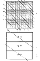
- 1
- x-Position
- 2
- Gemessene Tiefe,
- 3
- Gemessenen Entfernungen zum Lasersensor,
- 4
- Erkannte Grenzen der einzelnen optischen Elemente zur Berechnung der Aufbringungsparameter.
- 1a
- Receipts left field I l ,
- 1b
- Receive right partial image I r ,
- 2a
- Rectified left field R l ,
- 2 B
- Rectified right field R r ,
- 3a
- Matrix M l of the
features 1... K of the left partial image calculated per pixel, - 3b
- Matrix M r of the
features 1 ... K of the right-hand sub-image calculated per pixel, - 4
- Disparity card D,
- 5
- Pseudoholographically interlaced image B with M interlaced perspectives,
- 6
- Perspective map P,
- 7
- Autostereoscopic display,
- 11
- Rectify images and in
2a and2 B lay down, - 12
- Extract features and in
3a and3b lay down, - 13
- Calculate disparity card, if not supplied, and in
4 lay down, - 14
- Create pseudoholographic image B of the interlaced perspectives and in
5 lay down.
- 11
- Rectify images,
- 12
- Extract features,
- 13
- Create disparity map,
- 14
- Synthesize pseudo-holographic perspectives
- 21
- Begin,
- 22
- Import pictures,
- 23
- Read pictures ?,
- 24
- Disparity card available ?,
- 25
- Output pseudo-holographic image on display,
- 26
- Stop.
- 1
- Processor,
- 2
- Local memory,
- 3
-
Line calculation unit 1, - 4
- Line calculation unit n,
- 5
- Control unit
- 6
- Global storage unit,
- 7
- Single-chip implementation,
- 8th
- control bus
- 9
- data bus,
- 10
- Autostereoscopic display.
- A
- Old subpixel layout,
- N
- New subpixel layout,
- R
- Red,
- G
- Green,
- B
- Blue,
- W
- White
- 1-36
- Number of the perspective to be displayed in this subpixel.
- 1
- Left scene,
- 2
- Line of a disparity card,
- 3
- Left field,
- 4
-
Interim perspective 1, - 5
-
Interim perspective 2, - 6
-
Interim perspective 3, - 7
-
Intermediate Perspective 4, - 8th
-
Intermediate perspective 5, - 9
-
Interim perspective 6, - 10
- Right part of picture,
- 11
- Right scene,
- 12
- Right cover in the left part of the picture,
- 13
- Left cover in the right part of the picture.
- 1
- Left scene,
- 2a
- Right occlusion of the front object in the left part of the picture,
- 2 B
- Rear object,
- 2c
- Front object,
- 2d
- Left concealment of the front object in the right partial image
- 3
- Left field,
- 4
-
Interim perspective 1, - 5
-
Interim perspective 2, - 6
-
Interim perspective 3, - 7
-
Intermediate Perspective 4, - 8th
-
Intermediate perspective 5, - 9
-
Interim perspective 6, - 10
- Right part of picture,
- 11
- Right scene,
- 12
- Right cover in the left part of the picture,
- 13
- Left cover in the right part of the picture,
- 14a
- Cross-over image segment C 1 in the left partial image,
- 14b
- Cross-over image segment C 1 in the right-hand sub-image,
- P1
- j r / 3 is to the left of jrmin_PositionNew,
- P2
- j r / 3 is between jrmin_positionNew and jrmax_positionNew,
- P3
- j r / 3 is to the right of jrmax_PositionNeu.
- N
- No,
- Y
- Yes,
- 1
- Begin,
- 2
- j = 1,
- 3
- j ≥ NrPixel ?,
- 4
- Stop,
- 5
- j = j + 1,
- 6
- Where (i, j) ≥ 0 ?,
- 7
- Crossover (j) = 0,
- 8th
- Where (i, j) <where (i, j - 1) ?,
- 9
- CrossAnf = j,
- 10
- Crossover (j) = 1,
- 11
- j = j + 1,
- 12
- Where (i, j)> Where (i, CrossAnf - 1) ?.
- N
- No,
- Y
- Yes,
- A
- Starting point A,
- B
- Point of connection B,
- C
- Starting point C,
- D
- Point of connection D,
- 1
- Begin,
- 2
- jl = -1,
- 3
- jl = jl + 1,
- 4
- jl ≥ NrPixel ?,
- 5
- Crossover (jl) = 0 ?,
- 6
- jlmin = jl,
- 7
- Crossover (jl) = 0 or jl ≥ NrPixel ?,
- 8th
- jl = jl + 1,
- 9
- jlmax = jlmin,
- 10
- jrmin = jlmin,
- 11
- Where (jlmin) <jlmin ?,
- 12
- jrmin = where to (jlmin),
- 13
- jrmax = jlmax,
- 14
- Where (jlmax)> jrmax ?,
- 15
- jrmax = where to (jlmax),
- 16
- j_scale = (jlmax - jlmin + 1) / (where to (jlmax) - where to (jlmin) + 1),
- 17
- jr = (jrmin - 1) * 3,
- 18
- jr> jrmax * 3 ?,
- 19
- Get P (i, jr),
- 20
- P (i, j) = 0 ?,
- 21
- jr = jr + 1,
- 22
- P (i, j) = NS - 1 ?,
- 23
- jrmin_positionCalculate new
- 24
- jrmin_Position New> jr / 3 ?,
- 25
- jrmax_positionCalculate new,
- 26
- jrmax_PositionNew <jr / 3 ?,
- 27
- CrossoverPixel = jlmin + (jr / 3 - jrmin_positionNew) * j_scale,
- 28
- Get right subpixels of CrossoverPixel from left field,
- 29
- Stop.
- N
- No,
- Y
- Yes,
- A
- Starting point A,
- B
- Point of connection B,
- 1
- Begin,
- 2
- Crossover preprocessing,
- 3
- jr = 0; jl = 0,
- 4
- jl = jl +1,
- 5
- jr / 3> NrPixel ?,
- 6
- Crossover postprocessing,
- 7
- Stop,
- 8th
- Get P (i, jr),
- 9
- jr = jr +1,
- 10
- P (i, jr) = 0 ?,
- 11
- Fetch subpixels from the left field,
- 12
- P (i, jr) = N - 1 ?,
- 13
- Fetch subpixels from the right field,
- 14
- above = false; bottom = false,
- 15
- top = false or bottom = false ?,
- 16
- Get subpixels,
- 17
- Recalculate jl_position,
- 18
- jl_positionNew = jr / 3 ?,
- 19
- j_oben = jl; j_unten = jl; top = true; bottom = true,
- 20
- jl_positionnew> jr / 3 ?,
- 21
- j_oben = jl; above = true,
- 22
- jl = jl - 1,
- 23
- Crossover (jl) = 1 or D (i, jl) = -1 ?,
- 24
- j_unten = jl; bottom = true,
- 25
- jl = jl + 1,
- 26
- Crossover (jl) = 1 or D (i, jl) = -1 ?,
- 1
- x position
- 2
- Measured depth,
- 3
- Measured distances to the laser sensor,
- 4
- Detected limits of the individual optical elements for the calculation of the application parameters.
Detaillierte Beschreibung SoftwareDetailed description software
Im Folgenden werden alle Schritte im Einzelnen beschrieben. Im Rahmen dieser Patentschrift wird davon ausgegangen, dass durch ein Empfangsmodul z. B. über Antenne oder Internet eine Bildfolge von Stereobildern empfangen wird, dekodiert wird und in den Speicherbereichen Il und Ir zur Verfügung gestellt wird. Dieses Format wird hier exemplarisch angenommen. Der Empfang anderer 3D-Formate ist hier nicht genauer beschrieben und sei dem kundigen Lesen überlassen. Nach dem Empfang wird das Stereobild auf die Auflösung des angeschlossenen pseudoholographischen Displays vergrößert bzw. verkleinert. Ein Display der Auflösung 19.200×10.800 Pixel kann als hochauflösend hier angenommen werden. In diesem Fall wird z. B. ein Stereo-HD-Bild zehnfach horizontal und vertikal vergrößert.In the following, all steps are described in detail. In the context of this patent, it is assumed that by a receiving module z. B. is received via antenna or Internet, an image sequence of stereo images, is decoded and in the memory areas I l and I r available. This format is assumed here by way of example. The reception of other 3D formats is not described here in any detail and is left to expert reading. After receiving the stereo image is enlarged or reduced to the resolution of the connected pseudo-holographic display. A display of resolution 19,200 × 10,800 pixels can be assumed as high-resolution here. In this case, z. B. a stereo HD image ten times horizontally and vertically enlarged.
In einem ersten Schritt wird die Rektifizierung durchgeführt. Diese Verfahren sind in der Literatur bereits ausgiebig beschrieben und sollen hier nicht wiederholt werden. In der vorliegenden Implementierung werden im linken Teilbild Il neun markante Punkte, welche gleichmäßig über das Bild verteilt sind, nach dem SURF-Verfahren gesucht. Die Koordinate eines jeden markanten Punktes wird als Mittelpunkt eines Suchblockes im rechten Teilbild Ir verwendet. In diesem Suchblock wird der ähnlichste Punkt im rechten Teilbild Ir gesucht. Mit Hilfe der Disparitäten der neun markanten Punkte wird eine lineare Transformationsmatrix definiert, mit welcher jedes der Teilbilder Il und Ir nach Rl und Rr rektifiziert wird:
Il → Rl und Ir → Rr.In a first step, the rectification is performed. These methods are already extensively described in the literature and will not be repeated here. In the present implementation, in the left field I l, nine landmarks evenly distributed over the image are searched for the SURF method. The coordinate of each prominent point is used as the center of a search block in the right field I r . In this search block, the most similar point in the right field I r is searched. By means of the disparities of the nine prominent points a linear transformation matrix is defined, with which each of the partial images I l and I r to R l and R r is rectified:
I l → R l and I r → R r .
Damit ist die Rektifizierung durchgeführt, sodass nun die Epipolaren parallel zu den Zeilen des Bildes laufen und alle späteren Operationen zeilenweise durchgeführt werden können. With this, the rectification is carried out, so that now the epipolars can run parallel to the lines of the image and all subsequent operations can be performed line by line.
Für eine qualitativ hochwertige dichte Disparitätskarte werden im zweiten Schritt die rektifizierten Teilbilder durch verschiedene Merkmale ergänzt.For a high-quality dense disparity map, in the second step, the rectified sub-images are supplemented by various features.
Diese Merkmale werden in den folgenden Schritten einerseits zur Verbesserung der Sicherheit der berechneten Disparitätskarte verwendet und andererseits auf dem autostereoskopischen Display visualisiert, um die Erzeugung des Raumbildes im Gehirn zu erleichtern.On the one hand, these features are used in the following steps to improve the safety of the calculated disparity map and, on the other hand, are visualized on the autostereoscopic display to facilitate the generation of the spatial image in the brain.
Die spätere Berechnung der Disparitätskarte ist dadurch gekennzeichnet, dass sie sehr schnell durchgeführt werden kann, weil die Disparitäten massiv parallel für jede Zeile getrennt berechnet werden. Dies hat jedoch den Nachteil, dass lokale Merkmale wie z. B. Formen, Texturen oder Kanten nicht berücksichtigt werden. Daher werden in der Merkmalextraktionsphase verschiedene Merkmale berechnet, welche lokale Eigenschaften beschreiben.The later calculation of the disparity map is characterized in that it can be carried out very quickly, because the disparities are calculated massively separately in parallel for each line. However, this has the disadvantage that local features such. As shapes, textures or edges are not taken into account. Therefore, in the feature extraction phase, various features are described that describe local properties.
In der Literatur wird eine sehr große Zahl von Merkmalen und ihre Berechnung beschrieben. Nur exemplarisch und ohne Anspruch auf Vollständigkeit sollen hier zwei Verfahren und ihre massiv parallele Implementierung beschrieben werden:
- 1. SURF: Speed up Robust Features [1] und
- 2. Sobel-Edge-Detector [3].
- 1. SURF: Speed up Robust Features [1] and
- 2. Sobel edge detector [3].
SURF-Merkmalsextraktion:SURF feature extraction:
Dieses Verfahren beruht darauf, dass für jeden Pixel die Determinante der Hesse-Matrix approximiert wird. Dabei wird wie folgt vorgegangen.This method is based on approximating the determinant of the Hesse matrix for each pixel. The procedure is as follows.
In einer Matrix Isum, welche jeweils für das linke und rechte rektifizierte Teilbild erstellt wird, werden für jeden Pixel die Teilsummen der Grauwerte des unteren Bildbereiches gespeichert: 
In der Berechnung wird so vorgegangen, dass zunächst jeder Zeile i eine Zeilenrecheneinheit i zugeordnet wird, welche die Teilsumme rekursiv berechnet:
Die so berechnete Matrix enthält nun für jedes Teilbild links und rechts die gewünschten Teilsummen. Nun wird jeder Zeile i wieder eine Recheneinheit i (= Zeilenrecheneinheit i) zugeordnet, welche zunächst die folgenden Zwischenwerte berechnet:
Danach ergibt sich
Die approximierte Determinante der Hessematrix wird sodann für jeden Pixel des rechten Teilbildes in der Merkmalsmatrix Mr(1) abgespeichert:
Die gleiche Vorgehensweise wird für jeden Pixel des linken Teilbildes R1 durchgeführt und in der Merkmalsmatrix Ml(1) abgespeichert. Insgesamt ergeben sich die Merkmalsmatrizen Mr(1) und Ml(1).The same procedure is carried out for each pixel of the left field R 1 and stored in the feature matrix M l (1). Overall, the feature matrices M r (1) and M l (1) result.
Da auf die rektifizierten Teilbilder Rr und Rl von allen Zeilenrecheneinheiten nur lesend zugegriffen wird und alle Zeilenrecheneinheiten i ihr Ergebnis in M(i, j, 1) abspeichern, gibt es keine Blockierungen und Wartezeiten. Weitere Details dieses Verfahrens sind z. B. in [1] beschrieben.Since the rectified fields R r and R l are read-only by all the line calculation units and all line calculation units i store their result in M (i, j, 1), there are no blocks and waiting times. Further details of this method are z. As described in [1].
Sobel-Merkmalsextraktion:Sobel feature extraction:
Der Sobel-Operator ist nur einer aus einer großen Anzahl von Kanten-Operatoren. Er soll daher hier nur exemplarisch beschrieben werden.The Sobel operator is just one of a large number of edge operators. He should therefore be described here only by way of example.
Für die Disparitätskarte ist ein Kanten-Operator von besonderer Bedeutung, da er hilft, dass bei der Zuordnung den Kanten eine höhere Bedeutung zugeteilt wird als den glatten Flächen. Da eine Kante immer auch eine regionale Eigenschaft ist, ermöglicht diese Vorgehensweise innerhalb einer Zeile auch die Eigenschaften von lokalen Regionen mit berücksichtigen zu können.For the disparity map, an edge operator is of particular importance, as it helps to assign more importance to edges than to smooth surfaces. Since an edge is always a regional property, this procedure within a row also allows to take into account the properties of local regions.
Der Sobel-Prewitt-Operator arbeitet z. B. mit 3×3.Matrizen, welche die Kanten in verschiedene Richtungen detektieren. Grundsätzlich sind hier horizontale, vertikale, links und rechts diagonale Kanten zu unterscheiden. Zu ihrer Detektion werden die folgenden 3×3-Matrizen verwendet: 
Eine Implementierung auf einem massiv parallelen System geht dabei so vor, dass jeder Zeile i eine Zeilenrecheneinheit i zugeordnet wird. Für alle Zeilen i und Spalten j wird das recheneinheiten-lokale Feld Kante(1) bis Kante(9) aus dem rechten rektifizierten Teilbild Rr wie folgt gefüllt:
Sodann berechnet jede Zeilenrecheneinheit i für jeden Index j:
Mr(i, j, 2) ergibt sich dann als Mr(i, j, 2) ≔ H1 + H2 + H3 + H4 für i = 1, ..., NZ und j = 1, ... NS. Dieses Verfahren wird in gleicher Weise für das linke rektifizierte Teilbild Rl durchgeführt. Insgesamt ergeben sich die Merkmalsmatrizen Mr(2) und Ml(2).M r (i, j, 2) then results as M r (i, j, 2) ≔ H 1 + H 2 + H 3 + H 4 for i = 1, ..., NZ and j = 1,. .. NS. This process is carried out in the same way for the left-hand rectified partial image R l . Overall, the feature matrices M r (2) and M l (2) result.
Besteht das empfangene Stereobild nur aus den Teilbildern Ir und Il und wurden keine weiteren Zusatzinformationen wie Disparitätskarte oder Tiefenkarte mit übertragen, so muss in einem Zwischenschritt die Disparitätskarte erstellt werden.If the received stereo image consists only of the partial images I r and I l and no further additional information such as disparity map or depth map has been transmitted, the disparity map must be created in an intermediate step.
Hierfür stehen jetzt die rektifizierten Bilder Rr und Rl und die Merkmalsmatrizen Mr und Ml zur Verfügung. Ohne Beschränkung der Allgemeingültigkeit soll hier exemplarisch das Verfahren nach Falkenhagen [4] beschrieben werden.For this purpose, the rectified images R r and R l and the feature matrices M r and M l are now available. Without limiting the general validity, the method according to Falkenhagen [4] is described here by way of example.
In der von Falkenhagen beschrieben Vorgehensweise wird für jede Zeile i die Verbundwahrscheinlichkeit des Disparitätsvektors d ^i maximiert: ![]()
![]()
Diese Vorgehensweise wird sodann in eine dynamische Optimierungsaufgabe umgeformt: 
Hierin bezeichnet corrlr(Rl(i, j), d(Rl(i, j))) die Korrelation zwischen dem Punkt Rl(i, j) des linken Teilbildes und dem Punkt Rr(i, j – d(Rl(i, j))) des rechter Teilbildes, d. h. des um die Disparität d(Rl(i, j)) verschobenen Punktes des linken Teilbildes.Here, corr lr (R l (i, j), d (R l (i, j))) denotes the correlation between the point R l (i, j) of the left field and the point R r (i, j-d (R l (i, j))) of the right field, ie the point of the left field shifted by the disparity d (R l (i, j)).
In der hier vorgelegten Offenlegung werden die folgenden Veränderungen vorgenommen:
- 1. Die einfachen Intensitätswerte Rr und Rl der Teilbilder werden für jeden Pixel durch den Merkmalsvektor Mr(i, j) ≔ (Mr(i, j, 1), ..., Mr(i, j, K)) und Ml(i, j) ≔ (Ml(i, j, 1), ..., Ml(i, j, K)) ersetzt. Dieser kann z. B. die Luminanzwerte und/oder die Farbwerte und/oder den Kanten-Operator Sobel und/oder den Struktur-Operator SURF enthalten. Weitere Merkmale können sinngemäß hinzugefügt werden.
- 1. The simple intensity values R r and R l of the fields are calculated for each pixel by the feature vector M r (i, j) ≔ (M r (i, j, 1),..., M r (i, j, K )) and M l (i, j) ≔ (M l (i, j, 1), ..., M l (i, j, K)). This can z. B. the luminance values and / or the color values and / or the edge operator Sobel and / or the structure operator SURF included. Other features can be added accordingly.
Dafür geht der Kreuzkorrelationskoeffizient corrlr(Rl(i, j), d(Rl(i, j))) unter Verwendung einer beliebigen Vektornorm über in: 
- 1. Die a-priori-Wahrscheinlichkeit kann nicht als Markov-
Prozess 1 . Ordnungdargestellt werden.
- 1. The a priori probability can not be considered a
Markov process 1 , orderbeing represented.
Die Pixel Rl(i, j) des linken als auch des rechten Teilbildes sind Projektionen von Raumpunkten, die zu gewissen Objekten der Szene gehören. Pixel Rl(i, j) eines gemeinsamen Objektes haben daher hinsichtlich ihres Projektionsverhaltens eine hohe Korrelation; zumindest solange man von starren Objekten ausgeht.The pixels R l (i, j) of the left as well as the right field are projections of space points belonging to certain objects of the scene. Pixels R l (i, j) of a common object therefore have a high correlation with respect to their projection behavior; at least as long as one starts from rigid objects.
Die allgemeine empirische Wahrscheinlichkeit einer Disparitätsänderung pΔd ist daher entsprechend korreliert mit der Projektion benachbarter Raumpunkte eines gemeinsamen Objektes. Dies geht dabei auch über die Zeilen hinaus und kann nicht unabhängig voneinander berechnet werden.The general empirical probability of a disparity change pΔd is therefore correspondingly correlated with the projection of adjacent spatial points of a common object. This also goes beyond the lines and can not be calculated independently.
Das hier vorgestellte und in [4] grundsätzlich beschriebene Verfahren wird in der Weise erweitert, dass zunächst für jeden Bildpunkt Rl(i, j) des Teilbildes Rl in einer Umgebung Uij, definiert durch
In Anlehnung an das vorher beschriebene Skalarprodukt wird corr(pij, pi*j*) wie folgt definiert:
Nachdem in einem ersten Schritt eine Disparitätskarte D berechnet wurde mit 
Alle geglätteten Disparitäten werden in der geglätteten Disparitätskarte D' zusammengefasst.All smoothed disparities are summarized in the smoothed disparity map D '.
Dieses Verfahren wird sowohl hierarchisch als auch zeitlich strukturiert, indem die Teilbilder Rl und Rr zusammen mit den Merkmalsmatrizen Ml und Mr in einer Informationspyramide verwendet werden. Auf der obersten Ebene wird eine Berechnung der Disparitätskarte iterativ solange durchgeführt bis die Zuordnungen von links nach rechts und umgekehrt konsistent sind.This method is structured both hierarchically and temporally by using the fields R l and R r together with the feature matrices M l and M r in an information pyramid. At the top level, a disparity map calculation is performed iteratively until the left to right mappings and vice versa are consistent.
Als Anfangswerte der Disparitätskarte werden dabei die Disparitäten des vorherigen Teilbildes Rl k-1 verwendet, sofern kein sogenannter „Hardcut” in der Bildsequenz zwischen dem aktuellen Stereobild k und dem vorherigen Stereobild k – 1 erkannt wird. Ist dies jedoch der Fall, wird die identische Disparitätskarte
Im Falle einer MPEG-Kompression kann man sich auf die dabei mit übertragenen Werte konstanter Bereiche beziehen und braucht diese Identifikation nicht noch einmal durchzuführen.In the case of MPEG compression, it is possible to refer to the values of constant areas that are transmitted with it and need not repeat this identification.
Durch diese Vorgehensweise wird eine gewisse Kontinuität in der Disparitätenkartenfolge erreicht und der sogenannte „Disparity Jitter” vermieden.This approach achieves a certain continuity in the disparity card sequence and avoids the so-called "disparity jitter".
Ist auf der obersten Ebene eine konsistente Disparitätskarte erstellt worden, so wird diese auf die nächstniedrigere Ebene expandiert und als Startkarte für die dortige detailliertere Disparitätskarte verwendet. In dieser Weise wird weiter vorgegangen, bis der unterste und damit höchste Detaillierungsgrad erreicht ist.If a consistent disparity map has been created at the top level, it will be expanded to the next lower level and used as the starting map for the more detailed disparity map there. In this way, the procedure continues until the lowest and thus highest level of detail has been reached.
Ist im vorherigen Schritt die Disparitätskarte berechnet worden oder wurde sie mit empfangen, so wird im nächsten Schritt die pseudoholographische Bildsynthese durchgeführt.If the disparity map was calculated in the previous step or was received with it, the pseudoholographic image synthesis is carried out in the next step.
Hier wird das in
Es kann dann der Fall sein, dass das linke Auge ein entfernteres Objekt O2 links von O1 sieht, während das rechte Auge das Objekt O2 rechts von O1 sieht. Dies soll im folgenden als Cross-Over-Effekt bezeichnet werden. in 
Zur Bestimmung der Werte dieses Feldes wird wie folgt vorgegangen:
Zunächst wird die i-te Zeile der Disparitätskarte D in ein Zuordnungsfeld überführt mit Wohin(j) ≔ j + D(i, j).The values of this field are determined as follows:
First, the i-th row of the disparity map D is transferred to an assignment field with where (j) ≔ j + D (i, j).
In diesem Feld sind Rechtsverdeckungen durch den Wert –1 gekennzeichnet. Ansonsten sind die Werte von Wohin immer größer gleich 0.In this field, legal occlusions are indicated by the value -1. Otherwise the values of Where are always greater than 0.
Im Feld Wohin sind Cross-Over-Effekte dadurch gekennzeichnet, dass Wohin(j) < Wohin(j – 1) ist. Dort beginnt ein Cross-Over-Bildsegment und der Index CrossAnf = j wird gespeichert. Das Ende dieses Bildsegmentes ist durch die Eigenschaft Wohin(j) > Wohin(CrossAnf – 1) gekennzeichnet.In the field Where are cross-over effects characterized in that where to (j) <where (j - 1) is. There begins a cross-over image segment and the index CrossAnf = j is stored. The end of this image segment is indicated by the property Where (j)> Where (CrossAnf - 1).
Daher wird eine Laufvariable j zunächst auf 1 gesetzt und fortlaufend inkrementiert. Crossover(j) wird auf 0 gesetzt. Trift die Laufvariable auf ein Pixel CrossAnf, für welchen gilt Wohin(CrossAnf) < Wohin(CrossAnf – 1) gilt, so beginnt dort das Cross-Over-Bildsegment und Crossover(j) wird dort beginnend auf 1 gesetzt. Nun wird j weiter inkrementiert bis die Bedingung Wohin(j) > Wohin(CrossAnf – 1) erfüllt ist. Ab dort wird Crossover(j) wieder auf 0 gesetzt bis zum nächsten Cross-Over-Bildsegment oder dem Ende der Zeile i. Ein Flussdiagramm dieser Cross-Over-Vorverarbeitung ist in
Im zweiten Teilschritt wird für jede Zeile eine Laufvariable jr über alle Subpixel des Displaybildes B laufen gelassen. Zur Erleichterung des Verständnisses wird in der hier vorliegenden Beschreibung angenommen, dass jeder Pixel aus 3 Subpixeln besteht. Daher wird beim Übergang vom Subpixel auf den zugehörigen Pixel immer durch 3 dividiert. Besteht ein Pixel aus mehr Subpixeln, z. B. 4 Subpixeln, so muss dementsprechend durch 4 dividiert werden. Mittels der oben festgelegten Laufvariablen jr wird zunächst die anzuzeigende Perspektive aus der Matrix P geholt. Diese Matrix P gibt für jeden Subpixel des Displays an, welche Perspektive dort angezeigt werden soll. Demgegenüber ist eine Laufvariable jl jeder Zeile des linken Teilbildes zugeordnet, welche zunächst auf 0 (dem linken Rand des Displaybildes B) gesetzt ist. Im Zusammenhang mit der Disparitätskarte D kann nun eine Variable jl_PositionNeu berechnet werden, welche angibt, auf welcher Pixelposition die P(i, jr)-te Perspektive des Pixels Rl(i, jl) des linken Teilbildes dargestellt würde. Ist diese Position größer als jr/3, so muss jl dekrementiert werden. Ist diese Position kleiner als jr/3, so muss jl inkrementiert werden. Dieses Verfahren wird so lange fortgesetzt bis eine Position j_unten gefunden ist, welche gerade unterhalb von jr/3 ist. In gleicher Weise wird jl so lange inkrementiert bzw. dekrementiert bis eine Position j_oben gefunden ist, welche gerade oberhalb von jr/3 ist.In the second sub-step, a running variable j r is run over all subpixels of the display image B for each line. For ease of understanding, it is assumed in the present description that each pixel consists of 3 subpixels. Therefore, the transition from the subpixel to the associated pixel is always divided by 3. If a pixel consists of more subpixels, z. B. 4 subpixels, it must be divided accordingly by 4. By means of the above-defined run variable j r , the perspective to be displayed is first fetched from the matrix P. This matrix P indicates for each subpixel of the display which perspective should be displayed there. In contrast, a running variable j l of each line of the left part of the image is assigned, which is initially set to 0 (the left edge of the display image B). In connection with the disparity map D, a variable jl_PositionNew can now be calculated, which indicates at which pixel position the P (i, j r ) -th perspective of the pixel R l (i, j l ) of the left partial image would be displayed. If this position is greater than j r / 3, j l must be decremented. If this position is smaller than j r / 3, then j l must be incremented. This process is continued until a position j_unten is found which is just below j r / 3. In the same way, j l is incremented or decremented until a position j_oben is found which is just above j r / 3.
In Abhängigkeit von der Differenz j_oben – j_unten und der Differenz Wohin(i, j_unten) – Wohin(i, j_oben) kann herausgefunden werden, ob zwischen j_unten und j_oben eine reguläre Disparität, eine Links-, eine Rechts-Verdeckung oder ein Cross-Over-Effekt vorliegt.Depending on the difference j_oben - j_unten and the difference Wohin (i, j_unten) - Where (i, j_oben) can be found out whether between j_unten and j_oben a regular disparity, a left, a right-occlusion or a cross-over Effect is present.
Hier sind die folgenden Fälle zu unterscheiden:
- 1. j-oben – j_unten ≤ 1 und Wohin(j_oben) – Wohin(j_unten) ≤ 1 Dies ist eine reguläre Disparität. Der Subpixel kann von Rl(i, j_oben) bzw. Rl(i, j_unten) geholt werden.
- 2. j-oben – j_unten > 1 und Wohin(j_oben) – Wohin(j_unten) ≤ 1 Dies ist eine Rechtsverdeckung. Der zugehörige Pixel muss aus Rl durch Interpolation zwischen Rl(i, j_unten) und Rl(i, j_oben) und Abbildung auf die Perspektive P(i, jr) errechnet werden. Daraus wird sodann der erforderliche Subpixel extrahiert.
- 3. j-oben – j_unten ≤ 1 und Wohin(j_oben) – Wohin(j_unten) > 1 Dies ist eine Linksverdeckung. Der zugehörige Pixel muss aus Rr durch Interpolation zwischen Rr(i, Wohin(j_unten)) und Rr(i, Wohin(j_oben)) und Abbildung auf die Perspektive P(i, jr) errechnet werden. Daraus wird sodann der erforderliche Subpixel extrahiert.
- 4. j-oben – j_unten > 1 und Wohin(j_oben) – Wohin(j_unten) > 1
In diesem Fall hat man ein Cross-Over-Bildsegment erreicht. Hier sind zwei Unterfälle zu unterscheiden:
4a. Wohin(i, j) = –1 für j_unten < j < j_oben
Dieser Fall ist wie eine Rechtsverdeckung zu behandeln. Das Bildsegment muss von links nach rechts ausgeblendet werden. (Siehe Nr.
12 in6 ) 4b. Wohin(i, j) ≥ 0 für j_unten < j < j_oben Dieser Fall ist wie eine Linksverdeckung zu behandeln. Das Bildsegment muss von links nach rechts eingeblendet werden. (Siehe Nr.13 in6 )
- 1. j-top - j_unten ≤ 1 and Where to (j_oben) - Where to (j_unten) ≤ 1 This is a regular disparity. The subpixel can be fetched from R l (i, j_oben) or R l (i, j_unten).
- 2. j-top - j_unten> 1 and where (j_oben) - where (j_unten) ≤ 1 This is a legal concealment. The corresponding pixel must be calculated from R l by interpolation between R l (i, j_unten) and R l (i, j_oben) and mapping to the perspective P (i, j r ). From this, the required subpixel is extracted.
- 3. j-up - j_unten ≤ 1 and Where to (j_up) - Where to (j_unten)> 1 This is a link obfuscation. The corresponding pixel has to be calculated from R r by interpolation between R r (i, Wohin (j_unten)) and R r (i, Wohin (j_oben)) and mapping to the perspective P (i, j r ). From this, the required subpixel is extracted.
- 4. j-top - j_unten> 1 and where (j_oben) - where (j_unten)> 1 In this case, you have reached a cross-over image segment. Here are two sub-cases: 4a. Where (i, j) = -1 for j_unten <j <j_oben This case is treated like a legal concealment. The image segment must be hidden from left to right. (See no.
12 in6 4b. Where (i, j) ≥ 0 for j down <j <j_ top This case is treated as a left concealment. The image segment must be displayed from left to right. (See no.13 in6 )
Diese Vorgehensweise wird fortgesetzt bis die Laufvariable jr am rechten Rand der i-ten Zeile des Displaybildes B der verkämmten Perspektiven angelangt ist.This procedure is continued until the run variable j r has arrived at the right edge of the i-th line of the display image B of the interlaced perspectives.
Cross-Over-Bildsegmente werden in diesem Teilschritt ignoriert.Crossover image segments are ignored in this substep.
Im dritten Teilschritt wird die Cross-Over-Nachverarbeitung durchgeführt. In diesem Teilschritt brauchen nur die Zwischenperspektiven bearbeitet zu werden. Das linke und rechte zugeführte Teilbild sind als Perspektive 0 und M – 1 gesetzt und sind automatisch richtig bearbeitet worden. Für die Zwischenperspektiven wird wie folgt vorgegangen:
Beginnend von links wird mittels einer Variablen jl der Anfang eines Cross-over-Bildsegmentes gesucht. Dieses ist wegen Crossover(j) = 1 leicht zu finden. Der linke Rand sei mit Pixelposition jlmin bezeichnet. Der rechte Rand sei mit jlmax bezeichnet. In
Beginning from the left, the beginning of a cross-over image segment is searched by means of a variable j l . This is easy to find because of crossover (j) = 1. The left edge is labeled pixel position jlmin. The right margin is labeled jlmax. In
Eine Laufvariable jr läuft nun vom linken Subpixel jrmin·3 bis zum rechten Subpixel jrmax*3. Für jeden dieser Subpixel kann wieder die anzuzeigende Perspektive P(i, jr) gewählt werden.A running variable j r now runs from the left subpixel jrmin * 3 to the right subpixel jrmax * 3. For each of these subpixels, the perspective P (i, j r ) to be displayed can again be selected.
Ist Perspektive P(i, jr) = 0 oder P(i, jr) = M – 1, so muss dort ein Subpixel aus dem zugeführten linken bzw. rechten Teilbild angezeigt werden. Dieser Fall ist jedoch schon vorher korrekt bearbeitet worden und kann hier ignoriert werden Mittels der gesuchten Perspektive P(i, jr) kann eine Position jrmin_PositionNeu wie folgt berechnet werden:
Ist jrmin_PositionNeu > jr/3, so liegt jr links vom zu überlagernden Cross-Over-Bereich in der Perspektive P(i, jr). In diesem Fall muss nichts geschehen. jr kann inkrementiert werden. Dieser Fall ist in
Von CrossoverPixel wird der entsprechende Subpixel ins Displaybild B der verkämmten Perspektiven übertragen. Dieser Fall ist in
Nun wird jl ≔ jlmax + 1 gesetzt und weiter inkrementiert bis zum nächsten Cross-Over-Bildsegment oder das Ende der Zeile mit jl ≥ NS – 1 erreicht ist. jr ≥ N – 1 am rechten Rand des Displaybildes angelangt ist.Now j l ≔ jlmax + 1 is set and further incremented until the next cross-over image segment or the end of the line with j l ≥ NS - 1 is reached. j r ≥ N - 1 has reached the right edge of the display image.
Ein Flussdiagramm zu diesem Verfahrensteilschritt der Cross-Over-Nachverarbeitung ist in
Eine Szene ohne Cross-Over-Bildsegment ist in
Mit den Teilschritten 1 bis 3 ist das gesamte Verfahren zur Bildsynthese in
Für die Beziehung zwischen jlmax – jlmin und Wohin(i, jlmax) – Wohin(i, jlmin) kann folgendes festgehalten werden:For the relationship between jlmax - jlmin and Wohin (i, jlmax) - where (i, jlmin) the following can be stated:
- 1. jlmax – jlmin = Wohin(i, jlmax) – Wohin(i, jlmin) In diesem Fall ist die Objektfläche des Cross-Over-Objektes parallel zur Stereobasis.1. jlmax - jlmin = where to (i, jlmax) - where to (i, jlmin) In this case, the object surface of the cross-over object is parallel to the stereo base.
- 2. jlmax – jlmin > Wohin(i, jlmax) – Wohin(i, jlmin) In diesem Fall ist die Objektfläche des Cross-Over-Objektes der linken Kamera mit dem linken Teilbild zugewandt. Hier sind Zwischenbereiche des Cross-Over-Bildbereiches wie Rechtsverdeckungen zu behandeln und müssen im Laufe des Überganges zum rechten Teilbild ausgeblendet werden. Die Vorgehensweise hierfür ist im Schritt für die reguläre Disparitätsverarbeitung beschrieben.2. jlmax - jlmin> where (i, jlmax) - where (i, jlmin) In this case, the object surface of the cross-over object is facing the left camera with the left partial image. Here, intermediate areas of the cross-over image area are to be treated as legal concealments and must be hidden in the course of the transition to the right partial image. The procedure for doing this is described in the step for regular disparity processing.
- 3. jlmax – jlmin < Wohin(i, jlmax) – Wohin(i, jlmin) In diesem Fall ist die Objektfläche des Cross-Over-Objektes der rechten Kamera mit dem rechten Teilbild zugewandt. Hier sind Zwischenbereiche des Cross-Over-Bildbereiches wie Linksverdeckungen zu behandeln und müssen im Laufe des Überganges zum rechten Teilbild eingeblendet werden. Die Vorgehensweise hierfür ist im Schritt für die reguläre Disparitätsverarbeitung beschrieben.3. jlmax - jlmin <where (i, jlmax) - where (i, jlmin) In this case, the object surface of the cross-over object faces the right camera with the right field. Here, intermediate areas of the cross-over image area are to be treated as left occlusions and must be superimposed during the transition to the right partial image. The procedure for doing this is described in the step for regular disparity processing.
Da alle Schritte sich immer nur auf die Zeile i beziehen eignet sich eine solche Vorgehensweise ganz besonders für eine massiv parallele Verarbeitung. Dies wird im Abschnitt über die Hardware-Struktur noch weiter erläutert werden.Since all steps always relate only to line i, such an approach is particularly suitable for massively parallel processing. This will be explained further in the section on the hardware structure.
Autostereoskopische Visualisierung von 2D-Bildern:
Mit der bisher dargelegten Beschreibung wird der Fall beschrieben, wie zu verfahren ist, wenn 3D-Bilder in einem dafür definierten Format empfangen werden. Im Falle des Empfanges von 2D-Bildern, wird im allgemeinen so verfahren, dass das Bild vollständig auf die Größe des Displays angepasst und sodann angezeigt wird. In der hier vorliegenden Offenlegung soll jedoch anders verfahren werden.Autostereoscopic visualization of 2D images:
The above description describes the case of how to proceed when receiving 3D images in a format defined therefor. In the case of receiving 2D images, generally, the image is completely adjusted to the size of the display and then displayed. In the present disclosure, however, to proceed differently.
Wird das 2D-Bild vollständig auf dem Display angezeigt, so hat der Betrachter den Eindruck das Bild befindet sich auf der Oberfläche des Displays. Unter Ausnutzung des vorher beschriebenen pseudoholographischen Bildsyntheseverfahrens soll nun jedoch wie folgt vorgegangen werden:
In einem ersten Schritt wird das empfangene 2D-Bild als linkes Teilbild verwendet. Als rechtes Teilbild wird das gleiche 2D-Bild jedoch um einen Betrag m > 0 nach rechts verschoben verwendet. Gleichzeitig wird eine Disparitätsmatrix der folgenden Art erzeugt:
In a first step, the received 2D image is used as a left partial image. However, as the right sub-image, the same 2D image is used shifted by an amount m> 0 to the right. At the same time a disparity matrix of the following kind is created:
Dadurch haben alle Betrachter den Eindruck, das 2D-Bild (welches noch als solches empfunden wird) schwebt in einem gewissen Abstand vor dem Display.As a result, all viewers have the impression that the 2D image (which is still perceived as such) floats in front of the display at a certain distance.
Wird das 2D-Bild um einen gewissen Betrag m < 0 nach links verschoben, so haben die Betrachter den Eindruck, das Bild wird ins Display nach innen verschoben. Dieser Fall ist theoretisch möglich, optisch aber nicht besonders beeindruckend.If the 2D image is shifted to the left by a certain amount m <0, then the observers have the impression that the image is shifted inwards into the display. This case is theoretically possible, but visually not very impressive.
Lässt man den Betrachter den Betrag m interaktiv wählen, z. B. mittels einer Fernbedienung, so kann der Betrachter sich den „Pop-out”- oder „Pop-in”-Effekt jederzeit selbst einstellen. Die Verarbeitungszeit dafür ist in jedem Fall minimal.If you let the viewer choose the amount m interactive, z. B. by means of a remote control, so the viewer can adjust the "pop-out" - or "pop-in" effect at any time. The processing time for this is minimal in any case.
Die Qualität des 2D-Eindruckes leidet unter dieser Vorgehensweise nicht, da die Auflösung des Displays größer ist als die Auflösung des 2D-Bildes. The quality of the 2D impression does not suffer from this approach because the resolution of the display is greater than the resolution of the 2D image.
Detaillierte Beschreibung HardwareDetailed description Hardware
Displaydisplay
Zur Anpassung an die anatomischen Gegebenheiten des menschlichen Auges werden zwei Eigenschaften berücksichtigt. Dies sind:
- 1. die Auflösung des Auges und
- 2. die Anzahl und Eigenschaften der Rezeptoren im Auge.
- 1. the resolution of the eye and
- 2. the number and characteristics of the receptors in the eye.
Die Auflösung des menschlichen Auges liegt i. A. zwischen 0,5' und 1.5'. Daher haben heutige Displays meistens einen Dot-Pitch von 0,2 bis 0,3 mm. Das heißt, ab einem Abstand von ca. 1 m sind die Pixel des Displays nicht mehr zu erkennen. Bei dem hier vorgestellten erfindungsgemäßen Display liegt die Linsenbreite des verwendeten Linsenrasters im Bereich von 0,2 mm. Das heißt ca. 125 LPI (Linsen pro Inch). Dadurch ist die Linsenstruktur ab einem Betrachtungsabstand von ca. 1 m nicht mehr zu erkennen. Die Anzahl der Subpixel, die hinter einer Linse liegen, liegt in der Größenordnung von 10 Subpixeln pro Linse. Das heißt, dass der Dot-Pitch eines pseudoholographischen Displays in der Größenordnung von ca. 0,06 mm liegt. Während man bei konventionellen Displays z. B. 1920×1080 Pixel (HD-TV) darstellt, besteht ein hier vorgestelltes pseudoholographisches Display aus mindestens 19.200×1080 Pixeln.The resolution of the human eye is i. A. between 0.5 'and 1.5'. Therefore today's displays usually have a dot pitch of 0.2 to 0.3 mm. That is, from a distance of about 1 m, the pixels of the display are no longer visible. In the display according to the invention presented here, the lens width of the lens grid used is in the range of 0.2 mm. That is about 125 LPI (lenses per inch). As a result, the lens structure is no longer recognizable from a viewing distance of about 1 m. The number of subpixels behind a lens is on the order of 10 subpixels per lens. That is, the dot pitch of a pseudo-holographic display is on the order of about 0.06 mm. While in conventional displays z. B. 1920 × 1080 pixels (HD-TV) represents, there is a pseudo-holographic display presented here from at least 19,200 × 1080 pixels.
Das Linsenraster kann z. B. aus Lentikularlinsen oder auch aus Hexagonallinsen bestehen, die in diesem Falle einen Durchmesser von 0,2 mm besitzen.The lenticular can z. B. from lenticular lenses or hexagonal lenses, which in this case have a diameter of 0.2 mm.
Berücksichtigt man, dass im menschlichen Auge ca. 6,5 Mio. Farbrezeptoren vorhanden sind und ca. 100 Mio. Hell/Dunkel-Rezeptoren, so ist ersichtlich, dass ca. 15 mal so viele Hell/Dunkel-Rezeptoren vorhanden sind wie Farbrezeptoren. Diese anatomische Gegebenheit hatte ihren Niederschlag in den früher häufiger verwendeten Kompressionsparametern 4:2:2 gefunden. Bei der 4:2:2-Kompression werden doppelt so viele Schwarz/Weiß-Daten wir Farbdaten übertragen, weil man berücksichtigte, dass das menschliche Auge die Farbinformation sehr viel grober auflöst. Andererseits verwendet das menschliche Gehirn für die Erzeugung des inneren Raumbildes zu einem sehr großen Teil die Kanteninformation. Kanten geben mit den dort vorhandenen Rechts- und Linksverdeckungen Auskunft über die Vorne/Hinten-Beziehung von Objekten.Considering that in the human eye about 6.5 million color receptors are present and about 100 million light / dark receptors, it can be seen that about 15 times as many light / dark receptors are available as color receptors. This anatomical condition was reflected in the previously used compression parameters 4: 2: 2. In 4: 2: 2 compression, twice as much black and white data is transmitted as color data, because it was considered that the human eye resolves the color information much more roughly. On the other hand, the human brain uses the edge information to a great extent for the generation of the inner space image. Edges give information about the front / back relationship of objects with the existing right and left covers.
In einer ersten Ausführung werden daher die bekannten Subpixel RGB oder YMC durch Hell/Dunkel-Subpixel ergänzt, welche die in der Merkmalextraktionsphase durch die Kanten-Operatoren erzeugte Kanteninformation anzeigen.In a first embodiment, therefore, the known subpixels RGB or YMC are supplemented by light / dark subpixels which indicate the edge information generated in the feature extraction phase by the edge operators.
Homogene Flächen enthalten keine Kanten. Die Hell/Dunkel-Subpixel stellen dort im Bild keine Information dar.Homogeneous surfaces contain no edges. The light / dark subpixels do not represent any information in the image.
Kanten werden in den Hell/Dunkel-Subpixeln gemäß der Intensität der erkannten Kante heller dargestellt. Dadurch werden die im Bild vorhandenen Kanten hervorgehoben und durch die 100 Mio. Hell/Dunkel-Rezeptoren leichter erkannt.Edges are brightened in the light / dark subpixels according to the intensity of the detected edge. As a result, the edges present in the image are highlighted and more easily recognized by the 100 million light / dark receptors.
Das Gehirn hat es so leichter das innere Raumbild zu erzeugen. Muster auf homogenen Flächen werden im menschlichen Gehirn aufgrund des Lerneffektes als solche erkannt und beeinflussen den Raumbildeindruck nicht.The brain has it so easier to create the inner space image. Patterns on homogeneous surfaces are recognized as such in the human brain due to the learning effect and do not affect the spatial impression.
Die geometrische Anordnung der Hell/Dunkel-Subpixel kann erfindungsgemäß variiert werden. In
Zusätzlich wird die Aufteilung der Pixel in Farb-Subpixel (i. A. RGB-Subpixel) aufgehoben. Berücksichtigt man, dass die Zuordnung der Perspektiven für ein autostereoskopisches Display immer auf der Ebene der Subpixel mit Farb- und Hell/Dunkel-Subpixeln stattfindet, so wird in dem hier beschriebenen Display auf die Gruppierung von Subpixeln zu Pixeln verzichtet. Jeder Farb- oder Hell/Dunkel-Subpixel ist für sich ein eigenständiges Lichtelement, dem eine bestimmte Perspektive zugeordnet ist, und besitzt in horizontaler und vertikaler Richtung die gleiche Ausdehnung. Dies ist in
Die Herstellung eines solchen Displays ist auf Basis der OLED-Technologie kein Problem.The production of such a display based on the OLED technology is no problem.
In einer weiteren Ausführung, in welcher nur von den RGB- oder YMC-Subpixeln ausgegangen wird (wie sie in den bisherigen Displays gegeben sind) werden die Merkmale des verwendeten Kanten-Operators zur Hervorhebung der Kanten in den RGB-Subpixeln verwendet. Ein Pixel, z. B. bestehend aus den RGB-Subpixeln, wird wie folgt an die Anatomie des Auges angepasst:
Durch dieses Verfahren werden die Farbwerte des Stereobildes in den Kanten leicht aufgehellt (aber nicht farbverfälscht) und für die Hell/Dunkel-Rezeptoren leichter erkennbar.This method slightly brightens the color values of the stereo image in the edges (but not color distorted) and makes them easier to recognize for the light / dark receptors.
Auch hier können mehrere Merkmale wie folgt integriert werden:
Verarbeitungseinheitprocessing unit
In den vorherigen Kapiteln sind die Verfahrensschritte im Detail beschrieben worden. Wie vorher beschrieben empfängt das erfindungsgemäße hochauflösende pseudoholographische Display zunächst ein Stereobild in einem der bekannten Formate mit einer Auflösung von beispielsweise 1920×1080 je Bild. Es wird sodann auf die Auflösung des Displays skaliert, die hier zur Vereinfachung der Beschreibung mit 19.200×1080 angenommen sei.In the previous chapters, the process steps have been described in detail. As previously described, the high resolution pseudoholographic display of the invention first receives a stereo image in one of the known formats with a resolution of, for example, 1920 × 1080 per frame. It is then scaled to the resolution of the display, which is assumed here to simplify the description with 19,200 × 1080.
Dieses empfangene Stereobild wird analysiert und eine sehr große Anzahl von Zwischenperspektiven, z. B. 1.000 Perspektiven, daraus synthetisiert, welche nachfolgend auf einem Display z. B. mit Lentikularlinsen angezeigt werden.This received stereo image is analyzed and a very large number of intermediate perspectives, eg. B. 1,000 perspectives, synthesized from which below on a display z. B. be displayed with lenticular lenses.
Für die Analyse dieser Stereobilder wird die Durchführung in Echtzeit, d. h. i. A. in höchstens 20 ms gefordert. Dies erfordert eine sehr hohe Verarbeitungskapazität, welche nicht mehr in einer einzigen Verarbeitungseinheit erbracht werden kann.For the analysis of these stereo images, the execution in real time, i. H. i. A. in no more than 20 ms required. This requires a very high processing capacity, which can not be provided in a single processing unit.
In einer ersten Ausführungsform wird daher jeder Zeile des Displays eine eigene Verarbeitungseinheit mit dem erforderlichen lokalen Speicher zugeordnet. Diese wird im folgenden als „Zeilenrecheneinheit” bezeichnet.In a first embodiment, therefore, each line of the display is assigned its own processing unit with the required local memory. This is hereinafter referred to as "row calculation unit".
Neben diesen lokalen Zeilenrecheneinheiten werden alle Einheiten von einer Steuer- und Kontrolleinheit synchronisiert.In addition to these local line calculation units, all units are synchronized by a control and monitoring unit.
Daten wie z. B. die Ausgangsbilder, die rektifizierten Bilder, die Merkmalsvektoren oder das verkämmte Ausgabebild werden in einem globalen Speicher gehalten, auf welchen alle Zeilenrecheneinheiten parallel zugreifen können. Da alle Einheiten auf diese Daten nur lesend zugreifen oder schreibend nur auf die ihnen zugeordnete Zeile des Bildes und Displays bestehen keine Synchronisations- oder Blockierungsprobleme. Für ein Display mit einer Auflösung von 19.200×1080 sind also mindestens 1080 Zeilenrecheneinheiten erforderlich. Eine Implementierung als Chip oder Single-Board-Einheit sind für die heutige Chip-Technologie kein Problem, da bereits Grafikkarten mit einer gleichen Anzahl von Recheneinheiten, Shader genannt, existieren. Data such as The output images, the rectified images, the feature vectors, or the interleaved output image are held in a global memory that all of the row computation units can access in parallel. Since all units access this data only read-only or writing only on their associated line of the image and display, there are no synchronization or blocking problems. For a display with a resolution of 19,200 × 1080 so at least 1080 line calculation units are required. An implementation as a chip or single-board unit are no problem for today's chip technology, since graphics cards already exist with an equal number of processing units, called shaders.
In einer weiteren Ausführungsform werden jeder Zeile des Displays mehrere Verarbeitungseinheiten zugeordnet. Im Extremfall, der hier nicht ausgeschlossen ist, besitzt jeder Pixel eine eigene Verarbeitungseinheit.In a further embodiment, each row of the display is assigned a plurality of processing units. In extreme cases, which is not excluded here, each pixel has its own processing unit.
In der Phase der Bildanalyse zur Erzeugung der Disparitätskarte wird in diesem Falle ein aus der Literatur bekanntes iteratives Verfahren implementiert. In der Synthesephase wird die anfängliche Iterationsvariable il nicht mehr sequentiell für jeden Pixel inkrementiert, sondern es wird für jeden Pixel ir einer Zeile mit einem Startwert il ≔ ir begonnen. Das sodann gestartete Suchverfahren läuft wie beschrieben weiter.In the phase of image analysis for generating the disparity map, an iterative method known from the literature is implemented in this case. In the synthesis phase, the initial iteration variable i l is no longer incremented sequentially for each pixel, but a start value i l ≔ i r is started for each pixel i r of a row. The then started search process continues as described.
Die Struktur der pixelweise zugeordneten Zeilenrecheneinheiten ist in
Der globale Speicher wird in den Speicher für Bilddaten, Merkmalsdaten, für Disparitätskarte und für pseudoholographisches Ausgabebild unterteilt. Im Falle eines empfangenen Stereo-HD-Bildes mit zweimal 1920×1080 Pixeln und einem angeschlossenen Display mit der Auflösung 19.200×1080 muss mit folgender Speicherkapazität kalkuliert werden:
Bilddaten: 33 MB,
Merkmalsdaten: 0 MB,
Disparitätskarte: 80 MB,
Ausgabebild: 80 MB.The global memory is divided into the memory for image data, feature data, disparity map and pseudoholographic output image. In the case of a received stereo HD image with twice 1920 × 1080 pixels and a connected display with the resolution of 19,200 × 1080, the following storage capacity must be calculated:
Image data: 33 MB,
Characteristic data: 0 MB,
Disparity card: 80 MB,
Output image: 80 MB.
Dies ergibt einen erforderlichen Speicherbedarf von ca. 233 MB. Insgesamt besitzt das erfindungsgemäße hochauflösende pseudoholographische Display daher inklusive verschiedener Zwischenvariable eine Speicherkapazität von 256 MB. Auf diesem Display lassen sich bereits 10 Perspektiven hochauflösend ohne Pixelverlust darstellen.This results in a required memory requirement of approx. 233 MB. Overall, the inventive high-resolution pseudo-holographic display therefore has a storage capacity of 256 MB, including various intermediate variables. This display can already display 10 perspectives in high resolution without pixel loss.
Displays dieser Struktur sind automatisch auch für eine 2D-Darstellung von Bilder und Videos geeignet und brauchen nicht mechanisch oder elektronisch umgeschaltet zu werden. Der 2D-Eindruck ergibt sich dadurch, dass die Bildanalyse ausgelassen wird und bei der Bildsynthese nur auf das eine empfangene Bild wie im vorherigen Kapitel beschrieben zugegriffen wird.Displays of this structure are automatically suitable for a 2D representation of images and videos and need not be switched mechanically or electronically. The 2D impression results from omitting the image analysis and only accessing the one image received during image synthesis as described in the previous chapter.
HerstellungsprozessManufacturing process
Bei der Herstellung wird anders als bei konventionellen 2D-Displays vorgegangen. Während in der Vergangenheit autostereoskopische Displays immer so hergestellt wurden, dass vor ein 2D-Display ein optisches Element gesetzt wurde, ist dies hier nicht der Fall. In den bisher angewandten Herstellungsprozessen wird die bilderzeugende Einheit auf einem Substrat aufgebracht und der Rand so geschnitten, dass sich die gewünschte Displaygröße ergibt.The manufacturing process is different from conventional 2D displays. While in the past autostereoscopic displays were always made in such a way that an optical element was placed in front of a 2D display, this is not the case here. In the manufacturing processes used hitherto, the image-forming unit is applied to a substrate and the edge is cut so as to give the desired display size.
Bei autostereoskopischen Displays ist die Positionierung von bilderzeugender Einheit zum optischen Element von zentraler Bedeutung. Hier kommt es auf Lageparameter in der Größenordnung von 0.001 mm an. Ist z. B. die Lage der bilderzeugenden Einheit zum optischen Element nicht vollkommen parallel, so kann es zu Moire-Effekten bei der Betrachtung kommen.In autostereoscopic displays, the positioning of the imaging unit to the optical element is of central importance. Here it depends on position parameters in the order of 0.001 mm. Is z. For example, if the position of the imaging unit to the optical element is not perfectly parallel, moire effects may be encountered.
Es soll daher in dieser Patentanmeldung wie folgt vorgegangen:
- 1. Zuerst wird das optische Element als Linsenstruktur oder als Barrierenstruktur auf einem geeigneten Träger erzeugt.
- 2. Sodann wird eine erste elektrische Leitungsstruktur auf der Rückseite des Trägers aufgebracht. Dabei erkennt eine optische Sensoreinheit die exakte Lage des optischen Elementes und steuert durch diese Lageparameter den Aufbringungsprozess der bildgebenden Struktur.
- 3. Danach werden die Farbpixel RGB, RGBW oder andere Layouts auf der Leitungsstruktur aufgebracht. Dieser Schritt wird in gleicher Weise durch die vorher erkannten Lageparameter gesteuert.
- 4. In einem letzten Schritt wird die erforderliche ergänzende elektrische Leitungsstruktur auf der nun vorhandenen Subpixelstruktur aufgebracht. Auch dieser Schritt wird durch die vorher erkannten Lageparameter gesteuert.
- 1. First, the optical element is produced as a lens structure or as a barrier structure on a suitable carrier.
- 2. Then, a first electrical line structure is applied to the back of the carrier. In this case, an optical sensor unit detects the exact position of the optical element and controls the application process of the imaging structure by these positional parameters.
- 3. Thereafter, the color pixels RGB, RGBW or other layouts are applied to the line structure. This step is controlled in the same way by the previously detected positional parameters.
- 4. In a last step, the required complementary electrical line structure is applied to the now existing subpixel structure. This step too is controlled by the previously detected positional parameters.
Der Träger für das Display-Panel ist das optische Element selbst. Dadurch wird eine größere Genauigkeit bei der Zuordnung von Subpixel und optischem Element erreicht und gleichzeitig wird die Anzahl der Herstellungsschritte reduziert, wodurch auch die Herstellungszeit verringert wird. Ebenso ist eine Kalibrierung zwischen bilderzeugender Einheit und optischem Element nicht mehr erforderlich.The support for the display panel is the optical element itself. This provides greater accuracy in the subpixel and optical element assignment, while reducing the number of manufacturing steps, thereby reducing manufacturing time. Likewise, calibration between imaging unit and optical element is no longer required.
In einer ersten Ausführungsform besteht die optische Sensoreinheit aus einer Lichtquelle, welche die Vorderseite des optischen Elements beleuchtet. Auf der Rückseite des optischen Elements nimmt eine Kamera bzw. ein Scanner das Bild des durchleuchteten optischen Elementes auf. Dabei werden die Linsengrenzen (Rillen bzw. Barrieren) als schwarze Linien sichtbar. Durch einfache Bildverarbeitungsoperationen wird daraus die exakte Position der Linsengrenzen bzw. Barrieren erfasst und die Steuerparameter für den Aufbringungsprozess der Subpixel berechnet.In a first embodiment, the optical sensor unit consists of a light source which illuminates the front of the optical element. On the back of the optical element, a camera or a scanner picks up the image of the transilluminated optical element. The lens boundaries (grooves or barriers) are visible as black lines. Simple image processing operations are used to detect the exact position of the lens boundaries or barriers and to calculate the control parameters for the subpixel application process.
In einer zweiten Ausführungsform wird statt der Lichtquelle und Kamera ein Lasersensor verwendet, welcher von der Vorderseite den Abstand zur Oberfläche des optischen Elementes misst. Die Rillen bzw. Barrieren werden dabei durch einen größeren Abstand zum Lasersensor detektiert. Auch hier können wieder die Lageparameter der Linsen- bzw. Barrierestruktur berechnet und für den Aufbringungsprozess verwendet werden. Ein Diagramm eines solchen zeilenweisen Scans des Lasersensors ist in
Referenzenreferences
-
1.
H. Bay, T. Tuytelaars and L. V. Gool, ”SURF: Speeded Up Robust Features”, Computer Vision and Image Understanding, 110(3), 2008, pp. 346–359 H. Bay, T. Tuytelaars and LV Gool, "SURF: Speeded Up Robust Features", Computer Vision and Image Understanding, 110 (3), 2008, pp. 346-359 -
2.
M. Bleyer and M. Gelautz, ”Temporally Consistent Disparity Maps from uncalibrated Stereo Videos”, Proceedings of the 6th International Symposium an Image and Signal Processing and Analysis (ISPA 2009), Special Session an Stereo Analysis and 3D Video/TV, pp. 383–387 M. Bleyer and M. Gelautz, "Temporally Consistent Disparity Maps from Unbalanced Stereo Videos", Proceedings of the 6th International Symposium on Image and Signal Processing and Analysis (ISPA 2009), Special Session on Stereo Analysis and 3D Video / TV, pp. 383-387 -
3.
W. K. Pratt, ”Digital Image Processing”, A Wiley-Interscience Publication, 1991, ISBN 0-471-85766-1, pp. 553 ff WK Pratt, "Digital Image Processing", A Wiley-Interscience Publication, 1991, ISBN 0-471-85766-1, pp. 553 ff -
4.
L. Falkenhagen, ”Blockbasierte Disparitätsschätzung unter Berücksichtigung statistischer Abhängigkeiten der Disparitäten”, 2001, Fortschritt-Berichte VDI Reihe 10, Nr. 657 ISBN 3-18-365710-4 L. Falkenhagen, "Block-based Disparity Estimation Considering Statistical Dependencies of Disparities", 2001, Progress Reports VDI Series 10, No. 657 ISBN 3-18-365710-4 -
5.
B. Girod, G. Greiner, H. Niemann, „Principles of 3D Image Analysis and Synthesis”, Kluwer Academic Publishers, 2002, ISBN 0-7923-4850-4 Girod, G. Greiner, H. Niemann, "Principles of 3D Image Analysis and Synthesis", Kluwer Academic Publishers, 2002, ISBN 0-7923-4850-4 -
6.
O. Faugeras and Q-T Luong, ”The Geometry of Multiple Images”, MIT Press, London, 2001, ISBN 0-262-06220-8 O. Faugeras and QT Luong, "The Geometry of Multiple Images", MIT Press, London, 2001, ISBN 0-262-06220-8 -
7.
O. Faugeras, ”Three-dimensional Computer Vision”, MIT Press, London, 2001, ISBN 0-262-06158-9 O. Faugeras, Three-dimensional Computer Vision, MIT Press, London, 2001, ISBN 0-262-06158-9 -
8.
P. Courtney, N. Thacker & C. Brown, ”A hardware architecture for image rectification and ground plane obstacle detection”, Proc. Int. Conf. On Pattern Recognition 1992, pp. 23–26 P. Courtney, N. Thacker & C. Brown, "A hardware architecture for image rectification and ground plane obstacle detection", Proc. Int. Conf. On Pattern Recognition 1992, pp. 23-26
ZITATE ENTHALTEN IN DER BESCHREIBUNG QUOTES INCLUDE IN THE DESCRIPTION
Diese Liste der vom Anmelder aufgeführten Dokumente wurde automatisiert erzeugt und ist ausschließlich zur besseren Information des Lesers aufgenommen. Die Liste ist nicht Bestandteil der deutschen Patent- bzw. Gebrauchsmusteranmeldung. Das DPMA übernimmt keinerlei Haftung für etwaige Fehler oder Auslassungen.This list of the documents listed by the applicant has been generated automatically and is included solely for the better information of the reader. The list is not part of the German patent or utility model application. The DPMA assumes no liability for any errors or omissions.
Zitierte PatentliteraturCited patent literature
- EP 2007/003546 [0021] EP 2007/003546 [0021]
- WO 2007/121970 [0064] WO 2007/121970 [0064]
Claims (11)
Priority Applications (14)
| Application Number | Priority Date | Filing Date | Title |
|---|---|---|---|
| DE102010009291A DE102010009291A1 (en) | 2010-02-25 | 2010-02-25 | Method and apparatus for an anatomy-adapted pseudo-holographic display |
| KR1020127024214A KR101852209B1 (en) | 2010-02-25 | 2011-02-25 | Method for producing an autostereoscopic display and autostereoscopic display |
| US13/580,909 US9396579B2 (en) | 2010-02-25 | 2011-02-25 | Method for visualizing three-dimensional images on a 3D display device and 3D display device |
| JP2012554214A JP6060329B2 (en) | 2010-02-25 | 2011-02-25 | Method for visualizing 3D image on 3D display device and 3D display device |
| PCT/DE2011/000186 WO2011103865A2 (en) | 2010-02-25 | 2011-02-25 | Method and autostereoscopic display for producing three-dimensional images |
| JP2012554215A JP6142985B2 (en) | 2010-02-25 | 2011-02-25 | Autostereoscopic display and manufacturing method thereof |
| EP11720977A EP2540089A2 (en) | 2010-02-25 | 2011-02-25 | Method for visualizing three-dimensional images on a 3d display device and 3d display device |
| PCT/DE2011/000187 WO2011103866A2 (en) | 2010-02-25 | 2011-02-25 | Method for visualizing three-dimensional images on a 3d display device and 3d display device |
| PCT/DE2011/000188 WO2011103867A1 (en) | 2010-02-25 | 2011-02-25 | Method for producing an autostereoscopic display and autostereoscopic display |
| US13/580,924 US9324181B2 (en) | 2010-02-25 | 2011-02-25 | Method for producing an autostereoscopic display and autostereoscopic display |
| KR1020127024212A KR101825759B1 (en) | 2010-02-25 | 2011-02-25 | Method for visualizing three-dimensional images on a 3d display device and 3d display device |
| US15/078,596 US10134180B2 (en) | 2010-02-25 | 2016-03-23 | Method for producing an autostereoscopic display and autostereoscopic display |
| US15/181,282 US10229528B2 (en) | 2010-02-25 | 2016-06-13 | Method for visualizing three-dimensional images on a 3D display device and 3D display device |
| JP2016208015A JP6278323B2 (en) | 2010-02-25 | 2016-10-24 | Manufacturing method of autostereoscopic display |
Applications Claiming Priority (1)
| Application Number | Priority Date | Filing Date | Title |
|---|---|---|---|
| DE102010009291A DE102010009291A1 (en) | 2010-02-25 | 2010-02-25 | Method and apparatus for an anatomy-adapted pseudo-holographic display |
Publications (1)
| Publication Number | Publication Date |
|---|---|
| DE102010009291A1 true DE102010009291A1 (en) | 2011-08-25 |
Family
ID=44149833
Family Applications (1)
| Application Number | Title | Priority Date | Filing Date |
|---|---|---|---|
| DE102010009291A Ceased DE102010009291A1 (en) | 2010-02-25 | 2010-02-25 | Method and apparatus for an anatomy-adapted pseudo-holographic display |
Country Status (6)
| Country | Link |
|---|---|
| US (4) | US9396579B2 (en) |
| EP (1) | EP2540089A2 (en) |
| JP (3) | JP6060329B2 (en) |
| KR (2) | KR101825759B1 (en) |
| DE (1) | DE102010009291A1 (en) |
| WO (3) | WO2011103865A2 (en) |
Cited By (2)
| Publication number | Priority date | Publication date | Assignee | Title |
|---|---|---|---|---|
| ITTO20130784A1 (en) * | 2013-09-30 | 2015-03-31 | Sisvel Technology Srl | METHOD AND DEVICE FOR EDGE SHAPE ENFORCEMENT FOR VISUAL ENHANCEMENT OF DEPTH IMAGE BASED RENDERING |
| WO2015090003A1 (en) * | 2013-12-17 | 2015-06-25 | 京东方科技集团股份有限公司 | Display substrate, display panel and stereoscopic display apparatus |
Families Citing this family (9)
| Publication number | Priority date | Publication date | Assignee | Title |
|---|---|---|---|---|
| DE102010009291A1 (en) * | 2010-02-25 | 2011-08-25 | Expert Treuhand GmbH, 20459 | Method and apparatus for an anatomy-adapted pseudo-holographic display |
| US9363504B2 (en) * | 2011-06-23 | 2016-06-07 | Lg Electronics Inc. | Apparatus and method for displaying 3-dimensional image |
| EP2645724A4 (en) * | 2011-11-11 | 2014-08-06 | Sony Corp | Transmitting apparatus, transmitting method, receiving apparatus and receiving method |
| CN103959340A (en) * | 2011-12-07 | 2014-07-30 | 英特尔公司 | Graphics rendering technique for autostereoscopic three dimensional display |
| KR101349784B1 (en) * | 2012-05-08 | 2014-01-16 | 엘지디스플레이 주식회사 | A supporting member for attacting functional panel to display panel, display device having thereof, and mehtod of fabricating display device |
| TWI637348B (en) * | 2013-04-11 | 2018-10-01 | 緯創資通股份有限公司 | Apparatus and method for displaying image |
| CN105787877B (en) * | 2016-02-18 | 2018-11-23 | 精实万维软件(北京)有限公司 | A kind of more figure composition methods of dynamic and device |
| WO2020117841A1 (en) * | 2018-12-04 | 2020-06-11 | Sony Interactive Entertainment LLC | Fluid display device |
| US11056081B2 (en) * | 2019-08-09 | 2021-07-06 | Wuhan China Star Optoelectronics Semiconductor Display Technology Co., Ltd. | Display panel and display device |
Citations (4)
| Publication number | Priority date | Publication date | Assignee | Title |
|---|---|---|---|---|
| WO2006127555A2 (en) * | 2005-05-20 | 2006-11-30 | Clairvoyante, Inc. | Multiprimary color subpixel rendering with metameric filtering |
| WO2007121970A2 (en) | 2006-04-21 | 2007-11-01 | Expert Treuhand Gmbh | Method and device for the creation of pseudo-holographic images |
| WO2008100826A1 (en) * | 2007-02-13 | 2008-08-21 | Clairvoyante, Inc | Subpixel layouts and subpixel rendering methods for directional displays and systems |
| WO2008134829A2 (en) * | 2007-05-04 | 2008-11-13 | Interuniversitair Microelektronica Centrum | A method and apparatus for real-time/on-line performing of multi view multimedia applications |
Family Cites Families (47)
| Publication number | Priority date | Publication date | Assignee | Title |
|---|---|---|---|---|
| JPH0646461A (en) * | 1992-06-26 | 1994-02-18 | Matsushita Electric Ind Co Ltd | Flat stereoscopic image display device and its production |
| US5457574A (en) * | 1993-05-06 | 1995-10-10 | Dimension Technologies Inc. | Autostereoscopic display with high power efficiency |
| JP2944850B2 (en) * | 1993-05-25 | 1999-09-06 | シャープ株式会社 | 3D display device |
| JPH08220477A (en) * | 1995-02-13 | 1996-08-30 | Toppan Printing Co Ltd | Production of lenticular display and apparatus for production therefor |
| JP2000081918A (en) * | 1998-09-04 | 2000-03-21 | Canon Inc | Heater |
| JP3593466B2 (en) * | 1999-01-21 | 2004-11-24 | 日本電信電話株式会社 | Method and apparatus for generating virtual viewpoint image |
| FR2798708B1 (en) | 1999-09-17 | 2001-11-16 | Snfa | HYBRID BALL BEARING WITH AN OBLIQUE CONTACT, AND AN AXIAL STOP THEREWITH |
| AU2001237338A1 (en) * | 2000-01-25 | 2001-08-07 | 4D-Vision Gmbh | Method and system for the three-dimensional representation |
| US20020075566A1 (en) * | 2000-12-18 | 2002-06-20 | Tutt Lee W. | 3D or multiview light emitting display |
| US7103234B2 (en) * | 2001-03-30 | 2006-09-05 | Nec Laboratories America, Inc. | Method for blind cross-spectral image registration |
| GB0119176D0 (en) * | 2001-08-06 | 2001-09-26 | Ocuity Ltd | Optical switching apparatus |
| JP2003339060A (en) * | 2002-05-20 | 2003-11-28 | Denso Corp | Display apparatus for back image/side image of vehicle |
| JP2007072476A (en) * | 2002-07-29 | 2007-03-22 | Sharp Corp | Method for producing substrate with parallax barrier layer |
| AU2002952874A0 (en) * | 2002-11-25 | 2002-12-12 | Dynamic Digital Depth Research Pty Ltd | 3D image synthesis from depth encoded source view |
| JP4042615B2 (en) * | 2003-04-17 | 2008-02-06 | 株式会社デンソー | Image processing method and image processing apparatus |
| MXPA06003202A (en) * | 2003-09-22 | 2006-06-23 | Gene Dolgoff | Omnidirectional lenticular and barrier-grid image display. |
| JP4839598B2 (en) * | 2003-10-30 | 2011-12-21 | ブラザー工業株式会社 | Image display device |
| JP4402578B2 (en) * | 2004-03-31 | 2010-01-20 | 独立行政法人科学技術振興機構 | 3D display |
| JP4440066B2 (en) * | 2004-10-14 | 2010-03-24 | キヤノン株式会社 | Stereo image generation program, stereo image generation system, and stereo image generation method |
| JP4327758B2 (en) * | 2005-03-24 | 2009-09-09 | 株式会社東芝 | Stereoscopic image display device |
| JP4532372B2 (en) * | 2005-09-02 | 2010-08-25 | トヨタ自動車株式会社 | Road marking line detection device |
| JP2007081635A (en) * | 2005-09-13 | 2007-03-29 | Sanyo Epson Imaging Devices Corp | Display apparatus |
| JP2007110303A (en) * | 2005-10-12 | 2007-04-26 | Matsushita Electric Ind Co Ltd | Contour correction circuit |
| US8358330B2 (en) * | 2005-10-21 | 2013-01-22 | True Vision Systems, Inc. | Stereoscopic electronic microscope workstation |
| JP4337823B2 (en) * | 2005-11-04 | 2009-09-30 | セイコーエプソン株式会社 | Printer and printing method |
| TWI294750B (en) * | 2005-11-21 | 2008-03-11 | Whe Yi Chiang | Three dimensional organic electroluminescent display |
| WO2008023416A1 (en) * | 2006-08-23 | 2008-02-28 | Fujitsu Limited | Display element, and electronic paper and electronic terminal employing the same |
| WO2008029891A1 (en) * | 2006-09-07 | 2008-03-13 | Sharp Kabushiki Kaisha | Image display device, electronic device, and parallax barrier element |
| US20100103175A1 (en) * | 2006-10-25 | 2010-04-29 | Tokyo Institute Of Technology | Method for generating a high-resolution virtual-focal-plane image |
| JP2008112060A (en) * | 2006-10-31 | 2008-05-15 | Seiko Epson Corp | Display device |
| JP2008216971A (en) * | 2007-02-08 | 2008-09-18 | Seiko Epson Corp | Image display device |
| JP5263751B2 (en) * | 2007-06-07 | 2013-08-14 | 学校法人立命館 | Single screen display device |
| JP5115840B2 (en) * | 2007-08-23 | 2013-01-09 | 国立大学法人東京農工大学 | 3D display device |
| JP2009080144A (en) * | 2007-09-25 | 2009-04-16 | Toshiba Corp | Stereoscopic image display apparatus and stereoscopic image display method |
| JP2009162620A (en) * | 2008-01-07 | 2009-07-23 | Toshiba Corp | Inspection apparatus and its method |
| US8072448B2 (en) * | 2008-01-15 | 2011-12-06 | Google Inc. | Three-dimensional annotations for street view data |
| GB2457692A (en) * | 2008-02-21 | 2009-08-26 | Sharp Kk | A display device with a plurality of viewing modes |
| JP4987767B2 (en) * | 2008-03-18 | 2012-07-25 | 株式会社東芝 | 3D image display device manufacturing apparatus and 3D image display device manufacturing method |
| JP2010033447A (en) * | 2008-07-30 | 2010-02-12 | Toshiba Corp | Image processor and image processing method |
| KR101476219B1 (en) * | 2008-08-01 | 2014-12-24 | 삼성디스플레이 주식회사 | Method of manufacturing display device and apparatus using the same |
| KR20100033067A (en) * | 2008-09-19 | 2010-03-29 | 삼성전자주식회사 | Image display apparatus and method for both 2d and 3d image |
| JP4625517B2 (en) * | 2008-10-27 | 2011-02-02 | 富士フイルム株式会社 | Three-dimensional display device, method and program |
| JP4772163B2 (en) * | 2008-11-18 | 2011-09-14 | パナソニック株式会社 | Playback apparatus, playback method, and program for performing stereoscopic playback |
| AU2010207508B2 (en) * | 2009-01-20 | 2016-03-03 | Koninklijke Philips Electronics N.V. | Transferring of 3D image data |
| WO2010095081A1 (en) * | 2009-02-18 | 2010-08-26 | Koninklijke Philips Electronics N.V. | Transferring of 3d viewer metadata |
| JPWO2011007757A1 (en) * | 2009-07-13 | 2012-12-27 | 吉田 健治 | Parallax barrier for autostereoscopic display, autostereoscopic display, and method for designing parallax barrier for autostereoscopic display |
| DE102010009291A1 (en) * | 2010-02-25 | 2011-08-25 | Expert Treuhand GmbH, 20459 | Method and apparatus for an anatomy-adapted pseudo-holographic display |
-
2010
- 2010-02-25 DE DE102010009291A patent/DE102010009291A1/en not_active Ceased
-
2011
- 2011-02-25 WO PCT/DE2011/000186 patent/WO2011103865A2/en active Application Filing
- 2011-02-25 JP JP2012554214A patent/JP6060329B2/en active Active
- 2011-02-25 WO PCT/DE2011/000187 patent/WO2011103866A2/en active Application Filing
- 2011-02-25 EP EP11720977A patent/EP2540089A2/en not_active Withdrawn
- 2011-02-25 WO PCT/DE2011/000188 patent/WO2011103867A1/en active Application Filing
- 2011-02-25 KR KR1020127024212A patent/KR101825759B1/en active IP Right Grant
- 2011-02-25 US US13/580,909 patent/US9396579B2/en not_active Expired - Fee Related
- 2011-02-25 KR KR1020127024214A patent/KR101852209B1/en active IP Right Grant
- 2011-02-25 US US13/580,924 patent/US9324181B2/en not_active Expired - Fee Related
- 2011-02-25 JP JP2012554215A patent/JP6142985B2/en active Active
-
2016
- 2016-03-23 US US15/078,596 patent/US10134180B2/en active Active
- 2016-06-13 US US15/181,282 patent/US10229528B2/en active Active
- 2016-10-24 JP JP2016208015A patent/JP6278323B2/en not_active Expired - Fee Related
Patent Citations (4)
| Publication number | Priority date | Publication date | Assignee | Title |
|---|---|---|---|---|
| WO2006127555A2 (en) * | 2005-05-20 | 2006-11-30 | Clairvoyante, Inc. | Multiprimary color subpixel rendering with metameric filtering |
| WO2007121970A2 (en) | 2006-04-21 | 2007-11-01 | Expert Treuhand Gmbh | Method and device for the creation of pseudo-holographic images |
| WO2008100826A1 (en) * | 2007-02-13 | 2008-08-21 | Clairvoyante, Inc | Subpixel layouts and subpixel rendering methods for directional displays and systems |
| WO2008134829A2 (en) * | 2007-05-04 | 2008-11-13 | Interuniversitair Microelektronica Centrum | A method and apparatus for real-time/on-line performing of multi view multimedia applications |
Non-Patent Citations (10)
| Title |
|---|
| B. Girod, G. Greiner, H. Niemann, "Principles of 3D Image Analysis and Synthesis", Kluwer Academic Publishers, 2002, ISBN 0-7923-4850-4 |
| H. Bay, T. Tuytelaars and L. V. Gool, "SURF: Speeded Up Robust Features", Computer Vision and Image Understanding, 110(3), 2008, pp. 346-359 |
| KOOI,Frank L.,TOET,Alexander:Visual comfort of binocular and 3D displays.In.:Displays,Vol.25,2004,S.99-108 * |
| L. Falkenhagen, "Blockbasierte Disparitätsschätzung unter Berücksichtigung statistischer Abhängigkeiten der Disparitäten", 2001, Fortschritt-Berichte VDI Reihe 10, Nr. 657 ISBN 3-18-365710-4 |
| M. Bleyer and M. Gelautz, "Temporally Consistent Disparity Maps from uncalibrated Stereo Videos", Proceedings of the 6th International Symposium an Image and Signal Processing and Analysis (ISPA 2009), Special Session an Stereo Analysis and 3D Video/TV, pp. 383-387 |
| O. Faugeras and Q-T Luong, "The Geometry of Multiple Images", MIT Press, London, 2001, ISBN 0-262-06220-8 |
| O. Faugeras, "Three-dimensional Computer Vision", MIT Press, London, 2001, ISBN 0-262-06158-9 |
| P. Courtney, N. Thacker & C. Brown, "A hardware architecture for image rectification and ground plane obstacle detection", Proc. Int. Conf. On Pattern Recognition 1992, pp. 23-26 |
| SANDIN,Daniel J.,[et.al.]:The VarrierTM Autostereoscopic Virtual Reality Display.In:International Conference on Computer Graphics and Interactiv Techniques,ACM SIGGRAPH 2005 Papers,S.894-903 * |
| W. K. Pratt, "Digital Image Processing", A Wiley-Interscience Publication, 1991, ISBN 0-471-85766-1, pp. 553 ff |
Cited By (4)
| Publication number | Priority date | Publication date | Assignee | Title |
|---|---|---|---|---|
| ITTO20130784A1 (en) * | 2013-09-30 | 2015-03-31 | Sisvel Technology Srl | METHOD AND DEVICE FOR EDGE SHAPE ENFORCEMENT FOR VISUAL ENHANCEMENT OF DEPTH IMAGE BASED RENDERING |
| US10049502B2 (en) | 2013-09-30 | 2018-08-14 | Sisvel Technology S.R.L. | Method and device for edge shape enforcement for visual enhancement of depth image based rendering of a three-dimensional video stream |
| WO2015090003A1 (en) * | 2013-12-17 | 2015-06-25 | 京东方科技集团股份有限公司 | Display substrate, display panel and stereoscopic display apparatus |
| US9964671B2 (en) | 2013-12-17 | 2018-05-08 | Boe Technology Group Co., Ltd. | Display substrate, display panel, and stereoscopic display device |
Also Published As
| Publication number | Publication date |
|---|---|
| WO2011103865A3 (en) | 2012-02-09 |
| KR101852209B1 (en) | 2018-04-25 |
| JP6142985B2 (en) | 2017-06-07 |
| US20130135720A1 (en) | 2013-05-30 |
| US10134180B2 (en) | 2018-11-20 |
| KR20130008555A (en) | 2013-01-22 |
| JP6278323B2 (en) | 2018-02-14 |
| WO2011103867A1 (en) | 2011-09-01 |
| KR20130036198A (en) | 2013-04-11 |
| JP2013527932A (en) | 2013-07-04 |
| WO2011103866A3 (en) | 2012-03-01 |
| US9396579B2 (en) | 2016-07-19 |
| WO2011103865A2 (en) | 2011-09-01 |
| WO2011103866A2 (en) | 2011-09-01 |
| US10229528B2 (en) | 2019-03-12 |
| US20160300517A1 (en) | 2016-10-13 |
| US20160205393A1 (en) | 2016-07-14 |
| US9324181B2 (en) | 2016-04-26 |
| EP2540089A2 (en) | 2013-01-02 |
| US20130147804A1 (en) | 2013-06-13 |
| KR101825759B1 (en) | 2018-03-22 |
| JP2013520890A (en) | 2013-06-06 |
| JP6060329B2 (en) | 2017-01-18 |
| JP2017078859A (en) | 2017-04-27 |
Similar Documents
| Publication | Publication Date | Title |
|---|---|---|
| DE102010009291A1 (en) | Method and apparatus for an anatomy-adapted pseudo-holographic display | |
| DE69735488T2 (en) | METHOD AND DEVICE FOR ALIGNING PICTURES | |
| DE69827232T2 (en) | MOSAIC IMAGE PROCESSING SYSTEM | |
| DE69531583T2 (en) | Image processing method and device | |
| DE19953595B4 (en) | Method and device for processing three-dimensional images | |
| EP2027728A2 (en) | Method and device for the creation of pseudo-holographic images | |
| DE102010038939A1 (en) | Image correction apparatus and method and method of making a transformation map therefor | |
| DE102007021518B4 (en) | Method of processing a video data set | |
| DE102010028668B4 (en) | Method for spatial representation | |
| DE102011008886A1 (en) | Method and apparatus for stereobase extension of stereoscopic images and image sequences | |
| DE112013004718B4 (en) | Image processing apparatus and method, and program, printer and display apparatus | |
| AT513369A2 (en) | Method for generating, transmitting and receiving stereoscopic images, and associated apparatus | |
| DE112014006493T5 (en) | Determine a scale of three-dimensional information | |
| DE102014206914A1 (en) | A stereoscopic treatment system | |
| EP3170307B1 (en) | Method for displaying three dimensional scene on an autostereoscopic display | |
| WO2011032642A1 (en) | Method and device for generating partial views and/or a stereoscopic image master from a 2d-view for stereoscopic playback | |
| EP2893510B1 (en) | Method and image processing apparatus for removing a visual object from an image | |
| DE60121443T2 (en) | Block-based motion or depth estimation | |
| DE102005036744B4 (en) | Method and device for autostereoscopic reproduction of 3D representations | |
| WO2007085482A1 (en) | Method for producing and displaying images which can be perceived in three dimensions | |
| DE10046788B4 (en) | Method and device for generating a combination image from image information stored in a data record | |
| DE112020001322T5 (en) | PICTURE SIGNAL DISPLAYING A SCENE | |
| EP4006822A1 (en) | Generation of a panoramic map for capturing a scene with multiple cameras | |
| EP2495978A1 (en) | Image output method for an auto-stereoscopic display | |
| DE112012002679T5 (en) | Apparatus and method for encoding / decoding multi-view images |
Legal Events
| Date | Code | Title | Description |
|---|---|---|---|
| R002 | Refusal decision in examination/registration proceedings | ||
| R003 | Refusal decision now final |
Effective date: 20111110 |