DE102010003475A1 - TURNING ANGLE MEASURING UNIT AND SPEED METER - Google Patents
TURNING ANGLE MEASURING UNIT AND SPEED METER Download PDFInfo
- Publication number
- DE102010003475A1 DE102010003475A1 DE102010003475A DE102010003475A DE102010003475A1 DE 102010003475 A1 DE102010003475 A1 DE 102010003475A1 DE 102010003475 A DE102010003475 A DE 102010003475A DE 102010003475 A DE102010003475 A DE 102010003475A DE 102010003475 A1 DE102010003475 A1 DE 102010003475A1
- Authority
- DE
- Germany
- Prior art keywords
- angle
- signal
- rotary shaft
- magnetic
- magnetic sensor
- Prior art date
- Legal status (The legal status is an assumption and is not a legal conclusion. Google has not performed a legal analysis and makes no representation as to the accuracy of the status listed.)
- Ceased
Links
Images
Classifications
-
- G—PHYSICS
- G01—MEASURING; TESTING
- G01P—MEASURING LINEAR OR ANGULAR SPEED, ACCELERATION, DECELERATION, OR SHOCK; INDICATING PRESENCE, ABSENCE, OR DIRECTION, OF MOVEMENT
- G01P3/00—Measuring linear or angular speed; Measuring differences of linear or angular speeds
- G01P3/42—Devices characterised by the use of electric or magnetic means
- G01P3/44—Devices characterised by the use of electric or magnetic means for measuring angular speed
- G01P3/48—Devices characterised by the use of electric or magnetic means for measuring angular speed by measuring frequency of generated current or voltage
- G01P3/481—Devices characterised by the use of electric or magnetic means for measuring angular speed by measuring frequency of generated current or voltage of pulse signals
- G01P3/487—Devices characterised by the use of electric or magnetic means for measuring angular speed by measuring frequency of generated current or voltage of pulse signals delivered by rotating magnets
-
- G—PHYSICS
- G01—MEASURING; TESTING
- G01D—MEASURING NOT SPECIALLY ADAPTED FOR A SPECIFIC VARIABLE; ARRANGEMENTS FOR MEASURING TWO OR MORE VARIABLES NOT COVERED IN A SINGLE OTHER SUBCLASS; TARIFF METERING APPARATUS; MEASURING OR TESTING NOT OTHERWISE PROVIDED FOR
- G01D5/00—Mechanical means for transferring the output of a sensing member; Means for converting the output of a sensing member to another variable where the form or nature of the sensing member does not constrain the means for converting; Transducers not specially adapted for a specific variable
- G01D5/12—Mechanical means for transferring the output of a sensing member; Means for converting the output of a sensing member to another variable where the form or nature of the sensing member does not constrain the means for converting; Transducers not specially adapted for a specific variable using electric or magnetic means
- G01D5/14—Mechanical means for transferring the output of a sensing member; Means for converting the output of a sensing member to another variable where the form or nature of the sensing member does not constrain the means for converting; Transducers not specially adapted for a specific variable using electric or magnetic means influencing the magnitude of a current or voltage
- G01D5/142—Mechanical means for transferring the output of a sensing member; Means for converting the output of a sensing member to another variable where the form or nature of the sensing member does not constrain the means for converting; Transducers not specially adapted for a specific variable using electric or magnetic means influencing the magnitude of a current or voltage using Hall-effect devices
- G01D5/145—Mechanical means for transferring the output of a sensing member; Means for converting the output of a sensing member to another variable where the form or nature of the sensing member does not constrain the means for converting; Transducers not specially adapted for a specific variable using electric or magnetic means influencing the magnitude of a current or voltage using Hall-effect devices influenced by the relative movement between the Hall device and magnetic fields
-
- G—PHYSICS
- G01—MEASURING; TESTING
- G01D—MEASURING NOT SPECIALLY ADAPTED FOR A SPECIFIC VARIABLE; ARRANGEMENTS FOR MEASURING TWO OR MORE VARIABLES NOT COVERED IN A SINGLE OTHER SUBCLASS; TARIFF METERING APPARATUS; MEASURING OR TESTING NOT OTHERWISE PROVIDED FOR
- G01D5/00—Mechanical means for transferring the output of a sensing member; Means for converting the output of a sensing member to another variable where the form or nature of the sensing member does not constrain the means for converting; Transducers not specially adapted for a specific variable
- G01D5/12—Mechanical means for transferring the output of a sensing member; Means for converting the output of a sensing member to another variable where the form or nature of the sensing member does not constrain the means for converting; Transducers not specially adapted for a specific variable using electric or magnetic means
- G01D5/244—Mechanical means for transferring the output of a sensing member; Means for converting the output of a sensing member to another variable where the form or nature of the sensing member does not constrain the means for converting; Transducers not specially adapted for a specific variable using electric or magnetic means influencing characteristics of pulses or pulse trains; generating pulses or pulse trains
- G01D5/24428—Error prevention
-
- G—PHYSICS
- G01—MEASURING; TESTING
- G01D—MEASURING NOT SPECIALLY ADAPTED FOR A SPECIFIC VARIABLE; ARRANGEMENTS FOR MEASURING TWO OR MORE VARIABLES NOT COVERED IN A SINGLE OTHER SUBCLASS; TARIFF METERING APPARATUS; MEASURING OR TESTING NOT OTHERWISE PROVIDED FOR
- G01D5/00—Mechanical means for transferring the output of a sensing member; Means for converting the output of a sensing member to another variable where the form or nature of the sensing member does not constrain the means for converting; Transducers not specially adapted for a specific variable
- G01D5/12—Mechanical means for transferring the output of a sensing member; Means for converting the output of a sensing member to another variable where the form or nature of the sensing member does not constrain the means for converting; Transducers not specially adapted for a specific variable using electric or magnetic means
- G01D5/244—Mechanical means for transferring the output of a sensing member; Means for converting the output of a sensing member to another variable where the form or nature of the sensing member does not constrain the means for converting; Transducers not specially adapted for a specific variable using electric or magnetic means influencing characteristics of pulses or pulse trains; generating pulses or pulse trains
- G01D5/24471—Error correction
-
- G—PHYSICS
- G01—MEASURING; TESTING
- G01P—MEASURING LINEAR OR ANGULAR SPEED, ACCELERATION, DECELERATION, OR SHOCK; INDICATING PRESENCE, ABSENCE, OR DIRECTION, OF MOVEMENT
- G01P3/00—Measuring linear or angular speed; Measuring differences of linear or angular speeds
- G01P3/42—Devices characterised by the use of electric or magnetic means
- G01P3/44—Devices characterised by the use of electric or magnetic means for measuring angular speed
- G01P3/48—Devices characterised by the use of electric or magnetic means for measuring angular speed by measuring frequency of generated current or voltage
- G01P3/481—Devices characterised by the use of electric or magnetic means for measuring angular speed by measuring frequency of generated current or voltage of pulse signals
- G01P3/489—Digital circuits therefor
-
- H—ELECTRICITY
- H02—GENERATION; CONVERSION OR DISTRIBUTION OF ELECTRIC POWER
- H02K—DYNAMO-ELECTRIC MACHINES
- H02K11/00—Structural association of dynamo-electric machines with electric components or with devices for shielding, monitoring or protection
- H02K11/01—Structural association of dynamo-electric machines with electric components or with devices for shielding, monitoring or protection for shielding from electromagnetic fields, i.e. structural association with shields
- H02K11/014—Shields associated with stationary parts, e.g. stator cores
- H02K11/0141—Shields associated with casings, enclosures or brackets
-
- H—ELECTRICITY
- H02—GENERATION; CONVERSION OR DISTRIBUTION OF ELECTRIC POWER
- H02K—DYNAMO-ELECTRIC MACHINES
- H02K11/00—Structural association of dynamo-electric machines with electric components or with devices for shielding, monitoring or protection
- H02K11/20—Structural association of dynamo-electric machines with electric components or with devices for shielding, monitoring or protection for measuring, monitoring, testing, protecting or switching
- H02K11/21—Devices for sensing speed or position, or actuated thereby
- H02K11/215—Magnetic effect devices, e.g. Hall-effect or magneto-resistive elements
Landscapes
- Physics & Mathematics (AREA)
- General Physics & Mathematics (AREA)
- Engineering & Computer Science (AREA)
- Power Engineering (AREA)
- Electromagnetism (AREA)
- Microelectronics & Electronic Packaging (AREA)
- Transmission And Conversion Of Sensor Element Output (AREA)
- Measurement Of Length, Angles, Or The Like Using Electric Or Magnetic Means (AREA)
Abstract
Ein Drehwinkel-Messgerät mit hoher Präzision wird durch die elektrische Korrektur des Drehwinkel-Messgeräts durch Drehen der Drehwelle bei konstanter Geschwindigkeit bereitgestellt.A rotation angle measuring device with high precision is provided by the electrical correction of the rotation angle measuring device by rotating the rotating shaft at a constant speed.

Description
HINTERGRUND DER ERFINDUNGBACKGROUND OF THE INVENTION
Die vorliegende Erfindung betrifft ein Drehwinkel-Messgerät, das Magnetwiderstandselemente (nachstehend auch als MR-Elemente bezeichnet) verwendet.The The present invention relates to a rotation angle measuring apparatus the magnetic resistance elements (hereinafter also referred to as MR elements referred to) used.
Ein
solches Drehwinkel-Messgerät, das MR-Elemente verwendet,
ist beispielsweise in
Als MR-Elemente sind anisotope Magneto- bzw. Magnetwiderstandselemente (nachstehend als AMR-Elemente bezeichnet) und Riesenmagneto- bzw. Riesenmagnetwiderstandselemente (nachstehend als GMR-Elemente bezeichnet) bekannt. Das allgemeine Prinzip des verwandten Standes der Technik wird nachstehend beschrieben, wobei ein Magnetfeld-Messgerät, das GMR-Elemente verwendet, als Beispiel dient.When MR elements are anisotropic magneto or magnetoresistance elements (hereinafter referred to as AMR elements) and giant magneto or Giant magnetic resistance elements (hereinafter referred to as GMR elements) known. The general principle of the related art is described below, wherein a magnetic field measuring device, The GMR elements used as an example.
Wenn an das GMR-Element eine Spannung angelegt wird, fließt Strom nach Maßgabe des Elementwiderstands. Der Elementwiderstand variiert in Abhängigkeit von der Differenz Δθ = θf – θp zwischen der Magnetisierungsrichtung θp der verstifteten Magnetschicht und der Magnetisierungsrichtung θf der freien Magnetschicht. Dementsprechend kann, wenn die Magnetisierungsrichtung θp der verstifteten Magnetschicht zuvor bekannt ist, die Magnetisierungsrichtung θf der freien Magnetschicht, d. h. die Ausrichtung des externen Magnetfelds, durch Messen des Widerstands des GMR-Elements und Verwenden der obigen Differenzbeziehung erfasst werden.When a voltage is applied to the GMR element, current flows in accordance with the element resistance. The element resistance varies depending on the difference Δθ = θ f -θ p between the magnetization direction θ p of the pinned magnetic layer and the magnetization direction θ f of the free magnetic layer. Accordingly, when the magnetization direction θ p of the pinned magnetic layer is previously known, the magnetization direction θ f of the free magnetic layer, ie, the orientation of the external magnetic field, can be detected by measuring the resistance of the GMR element and using the above difference relationship.
Der Mechanismus des Widerstands des GMR-Elements, der sich nach Maßgabe der Beziehung Δθ = θf – θp ändert, ist wie folgt.The mechanism of the resistance of the GMR element which changes in accordance with the relationship Δθ = θ f -θ p is as follows.
Die Magnetisierungsrichtung in einem Dünnfilm-Magnetfilm hängt mit der Richtung des Elektronenspins im Magnetfilm zusammen. Wenn Δθ = 0, neigt die Spinrichtung einer Mehrheit von Elektronen in der freien Magnetschicht dazu, mit der Spinrichtung einer Mehrheit von Elektronen in der verstifteten Magnetschicht zusammenzufallen. Wenn andererseits Δθ = 180°, neigt die Spinrichtung einer Mehrheit von Elektronen in der freien Magnetschicht dazu, entgegengesetzt zu der Spinrichtung einer Mehrheit von Elektronen in der verstifteten Magnetschicht zu sein.The Magnetization direction in a thin-film magnetic film hangs with the direction of the electron spin in the magnetic film together. If Δθ = 0, the spin tends to be a majority of electrons in the free Magnetic layer to, with the spin of a majority of electrons collapse in the pinned magnetic layer. On the other hand, if Δθ = 180 °, the spin direction tends to a majority of electrons in the free magnetic layer to, opposite to the Spinrichtung a majority of electrons in the pinned magnetic layer to be.
Im
zwischenliegenden Fall von Δθ = 0~180° wird
die Elektronenflugbahn etwas zwischen denjenigen liegend, die in
[Ausdruck 1][Expression 1]
-
R = R'0 + G / 2 (1 – cosΔθ) = R0 – G / 2 cosΔθ (1)R = R '0 + G / 2 (1 - cosΔθ) = R 0 - G / 2 cosΔθ (1)
Vorliegend wird G/R als der GMR-Koeffizient bezeichnet, der einen Wert von einigen bis mehreren zehn Prozent aufweist.present G / R is referred to as the GMR coefficient, which has a value of from a few to several ten percent.
Wie vorstehend beschrieben, wird das GMR-Element auch als Spin-Ventilvorrichtung bezeichnet, da elektrischer Strom (und damit elektrischer Widerstand) durch das GMR-Element in Abhängigkeit von der Richtung des Elektronenspins gesteuert werden kann.As As described above, the GMR element also becomes a spin valve device referred to as electric current (and therefore electrical resistance) by the GMR element depending on the direction of the electron spin can be controlled.
Des
Weiteren kann mit einem Magnetfilm, der eine geringe Filmdicke aufweist
(Dünnfilm-Magnetfilme), der Magnetisierungsvektor nicht
in der normalen Richtung (Richtung der Filmdicke) aufsteigen und
bleibt auf der Ebene der Oberfläche liegen, da der Entmagnetisierungsfaktor
in der normalen Richtung bezüglich der Oberfläche
extrem groß ist. Da jede der freien Magnetschicht
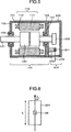
In
einem Magnetfeld-Messgerät bilden vier GMR-Elemente R1 (
[Ausdruck 2][Expression 2]
-
Rn = Rn0 + G / 2 (1 – cosθ) (2)R n = R n 0 + G / 2 (1 - cos) (2)
Und es folgt, dass für R2 und R4 (n = 2, 4):And it follows that for R 2 and R 4 (n = 2, 4):
[Ausdruck 3][Expression 3]
-
Rn = Rn0 + G / 2 (1 + cosθ) (3)R n = R n 0 + G / 2 (1 + cos) (3)
Wenn
eine Erregungsspannung e0 an die in ![]()
![]()
Wenn
die Ausdrücke (2) und (3) für den Ausdruck (4)
eingesetzt werden, wenn angenommen wird, dass Rn0's
für n = 1~4 gleich sind und dass R0 =
Rn0, dann folgt daraus, dass: [Ausdruck
5] ![]()
![]()
Da die Signalspannung ΔV proportional zu cosθ ist, kann auf diese Weise die Ausrichtung des Magnetfelds erfasst werden.There the signal voltage ΔV is proportional to cos θ, In this way, the orientation of the magnetic field can be detected.
Somit ist das Magnetwiderstandselement dadurch gekennzeichnet, dass es die Ausrichtung des Magnetfelds direkt messen kann.Thus, the magnetic resistance element is characterized in that it matches the alignment of the Ma gnetfelds can measure directly.
Es
ist ein Drehwinkel-Messgerät, das einen Drehmelder verwendet,
bekannt und ein solches ist in
Auf diese Weise, mit einem Drehwinkelsensor, dessen typisches Beispiel ein Drehmelder ist, der die Induktanz misst, beeinflusst die Genauigkeit des Luftspalts die Genauigkeit der Winkelmessung, so dass bei der Herstellung und Montage große Genauigkeit erforderlich ist. Des Weiteren verursacht eine Vergrößerung des Durchmessers der Rotorwelle eine Erhöhung der Größe des Drehmelders. Dies führt zu dem Problem der Kostensteigerung.On this way, with a rotation angle sensor, its typical example a resolver that measures the inductance affects the accuracy the air gap the accuracy of the angle measurement, so that at the Manufacture and assembly high accuracy required is. Furthermore causes an increase in the Diameter of the rotor shaft an increase in size of the resolver. This leads to the problem of cost increase.
Andererseits ist die Größe eines Magnetwiderstandselements, wie etwa eines GMR-Elements, ein Quadrat mit einer Seite von höchstens ein paar Millimetern. Daher kann man sagen, dass es von geringer Größe und leichtem Gewicht ist. Des Weiteren kann, da das Magnetwiderstandselement die Ausrichtung des Magnetfelds erfasst, ein Sensor von geringer Größe selbst dann verwendet werden, wenn eine dicke Rotorwelle benutzt wird.on the other hand is the size of a magnetoresistive element, such as a GMR element, a square with a side of at most a few millimeters. Therefore, it can be said that it is less Size and light weight is. Furthermore, because the magnetic resistance element, the orientation of the magnetic field detected, a sensor of small size itself used when a thick rotor shaft is used.
Wenn es gewünscht wird, ein Drehwinkel-Messgerät von geringer Größe zu bauen, kann dementsprechend die Verwendung von Magnetwiderstandselementen in vorteilhafter Weise ein gewünschtes Gerät von geringerer Größe und leichterem Gewicht bereitstellen. Wenn es weiterhin gewünscht ist, einen Elektromotor mit großer Belastbarkeit zu steuern, kann die Verwendung von Magnetwiderstandselementen in vorteilhafter Weise ein kostengünstiges Drehwinkel-Messgerät zur Verfügung stellen.If it is desired to have a rotation angle measuring device of Small size can be built accordingly the use of magnetic resistance elements in an advantageous manner a desired device of smaller size and lighter weight. If it continues to be desired is to drive an electric motor with high load capacity, may be the use of magnetic resistance elements in an advantageous manner a cost-effective rotation angle measuring device available put.
ZUSAMMENFASSUNG DER ERFINDUNGSUMMARY OF THE INVENTION
Bisher hat das Problem bestanden, dass, wenn in einem konventionellen Drehwinkel-Messgerät, das Magnetwiderstandselemente verwendet, ein Magnetsensor angebracht ist, die mechanische Ausrichtung des Magnetsensors schwierig ist.So far the problem has existed that when in a conventional angle of rotation measuring device, the magnetic resistance elements used, a magnetic sensor attached is, the mechanical alignment of the magnetic sensor is difficult.
Ein solches konventionelles Drehwinkel-Messgerät hat bisher unter dem Problem gelitten, dass, wenn es elektrisch korrigiert werden soll, ein Aktuator/Kodierer für die Korrektur vorbereitet und an das Gerät gekoppelt werden muss.One such conventional rotary angle meter has so far suffered from the problem that when it is electrically corrected to be prepared, an actuator / encoder for the correction and must be coupled to the device.
Weiterhin haben die obigen Probleme auch zu dem weiteren Problem geführt, dass eine Korrektur schwierig ist, wenn sie versucht wird, nachdem ein Drehwinkel-Messgerät in ein System eingebaut worden ist, sowie zu dem weiteren Problem, dass, wenn das bereits in ein System eingebaute Drehwinkel-Messgerät durch ein neues ausgetauscht wird, die Korrektur des neuen Geräts schwierig ist, das heißt, der Austausch eines Drehwinkel-Messgeräts in der Tat schwierig ist.Farther have the above problems also led to the further problem that a correction is difficult when attempted after a rotation angle measuring device has been installed in a system is, as well as to the further problem that, if that already in one System built-in angle measuring device by a new exchanged, the correction of the new device difficult is, that is, the replacement of a rotation angle measuring device indeed difficult.
Weiterhin weist ein konventionelles Drehwinkel-Messgerät das Problem auf, dass sich, wenn eine magnetische Substanz oder ein Material von hoher Permeabilität in der Nähe des konventionellen Drehwinkel-Messgeräts vorhanden ist, die Genauigkeit der Messung des Drehwinkels verschlechtert.Farther a conventional rotation angle measuring device has the problem on that, if a magnetic substance or a material of high permeability near the conventional one Angle encoder is present, the accuracy of Measurement of the rotation angle deteriorated.
Weiterhin weist ein konventionelles Drehwinkel-Messgerät das Problem auf, dass, wenn die Verteilung des Magnetfelds in komplizierter Weise aufgrund des Vorhandenseins einer magnetischen Substanz oder eines Materials von hoher Permeabilität in der Nähe des konventionellen Drehwinkel-Messgeräts geändert wird, eine Korrektur nicht ausreichend durchgeführt werden kann.Farther a conventional rotation angle measuring device has the problem on that, if the distribution of the magnetic field in more complicated Way due to the presence of a magnetic substance or a material of high permeability in the vicinity changed the conventional rotation angle meter a correction will not be done adequately can.
Noch weiter weist ein konventionelles Drehwinkel-Messgerät das Problem auf, dass, wenn es in einen wasserdichten Aufbau eingebaut wird, der Aufbau des Teils, durch das die Signalführungsdrähte herausgezogen werden, kompliziert wird, so dass die Gesamtmontage kompliziert wird.Yet Furthermore, a conventional rotation angle measuring device has the Problem on that, when installed in a waterproof construction is the structure of the part through which the signal guide wires be pulled out, gets complicated, so that the overall assembly gets complicated.
Noch weiter weist ein konventionelles Drehwinkel-Messgerät das Problem auf, dass die Berechung eines Drehwinkels aus der Ausgabe des Magnetsensors beträchtliche Zeit erfordert, so dass die Berechnung eines Drehwinkels auf die Messung des Drehwinkels der Drehwelle bei Hochgeschwindigkeitsbetrieb nicht schnell genug reagieren kann.Still further, a conventional rotation angle measuring apparatus has the problem that the calculation of a rotation angle from the output of the magnetic sensor requires considerable time, so that the calculation of a rotation angle does not affect the measurement of the rotation angle of the rotation shaft in high-speed operation can react fast enough.
Gemäß dieser Erfindung, die gemacht worden ist, um verschiedene der oben genannten Probleme zu lösen, wird ein Drehwinkel-Messgerät bereitgestellt, dessen Korrektur elektrisch durchgeführt werden kann, ohne auf einen Korrekturkodierer zurückzugreifen.According to this Invention that has been made to various of the above Solving problems becomes a rotation angle measuring device provided, the correction of which is carried out electrically without resorting to a correction encoder.
Als Ergebnis wurde es möglich, nur den Sensor selbst zu ersetzen, selbst nachdem das Gerät in einem System, wie etwa einem Kraftfahrzeug, eingebaut worden war. Dies liegt daran, dass das eigentliche Drehwinkel-Messgerät nach seinem Austausch korrigiert werden kann.When Result, it has been possible to replace only the sensor itself, even after the device is in a system, such as a Motor vehicle, had been installed. This is because that actual rotation angle measuring device after its replacement can be corrected.
Diese Erfindung wird als einige Ausführungsbeispiele wie folgt zusammengefasst.These Invention will be as follows as some embodiments summarized.
Ein Ausführungsbeispiel ist ein Drehwinkel-Messgerät, das einen Elektromotor mit einer Drehwelle umfasst, einen an einem Ende der Drehwelle angebrachten Magneten und einen Magnetsensor, dessen Ausgangssignal sich nach Maßgabe der Ausrichtung des den Magnetsensor umgebenden Magnetfelds ändert, und der ein Winkelsignal ausgibt, das den Drehwinkel der Drehwelle repräsentiert, wobei das Drehwinkel-Messgerät einen Korrekturablauf aufweist, in dem die Drehwelle des Elektromotors durch mehr als eine Umdrehung mit einer Drehzahl gedreht wird, deren Änderungsgeschwindigkeit im Lauf der Zeit bekannt ist, so dass das Winkelsignal korrigiert werden kann.One Embodiment is a rotation angle measuring device, which comprises an electric motor with a rotary shaft, one on one Magnet attached to the end of the rotary shaft and a magnetic sensor, whose output signal is in accordance with the orientation of the magnetic field surrounding the magnetic field changes, and which outputs an angle signal representing the rotation angle of the rotation shaft, wherein the rotation angle measuring device has a correction sequence, in which the rotary shaft of the electric motor by more than one revolution is rotated at a speed whose rate of change is known over time, so that corrects the angle signal can be.
Ein weiteres Ausführungsbeispiel ist ein Drehwinkel-Messgerät, das einen Elektromotor mit einer Drehwelle umfasst, einen an einem Ende der Drehwelle angebrachten Magneten und einen Magnetsensor, dessen Ausgangssignal sich nach Maßgabe der Ausrichtung des den Magnetsensor umgebenden Magnetfelds ändert, und der ein Winkelsignal ausgibt, das den Drehwinkel der Drehwelle repräsentiert, wobei der Elektromotor, die Drehwelle und der Magnet von einem Gestell bedeckt sind; der Magnetsensor außerhalb des Gestells angeordnet ist; das Gestell einen Gestellhauptkörper, der den Elektromotor abdeckt, und eine Gestellgehäuseeinheit, die den Magneten abdeckt, aufweist; die Gestellgehäuseeinheit aus einem Material hergestellt ist, das eine magnetische Suszeptibilität von höchstens 0,01 aufweist; und wobei das Drehwinkel-Messgerät einen Korrekturablauf aufweist, in dem die Drehwelle des Elektromotors durch mehr als eine Umdrehung mit einer Drehzahl gedreht wird, deren Änderungsgeschwindigkeit im Lauf der Zeit bekannt ist, so dass das Winkelsignal korrigiert werden kann.One Another embodiment is a rotation angle measuring device, which comprises an electric motor with a rotary shaft, one on one End of the rotary shaft attached magnets and a magnetic sensor whose Output signal in accordance with the orientation of the Magnetic sensor surrounding magnetic field changes, and the one Outputs angle signal that represents the angle of rotation of the rotary shaft, the electric motor, the rotary shaft and the magnet of a frame are covered; the magnetic sensor is arranged outside the frame is; the rack a rack main body, the electric motor covers, and a rack housing unit, the magnet covering, has; the rack housing unit from a Material is made that has a magnetic susceptibility of not more than 0.01; and wherein the rotation angle measuring device having a correction process in which the rotary shaft of the electric motor is rotated by more than one revolution at a speed whose rate of change is known over time, so that corrects the angle signal can be.
Ein noch weiteres Ausführungsbeispiel ist ein Drehwinkel-Messgerät, das einen Elektromotor umfasst, der eine Drehwelle, einem an einem Ende der Drehwelle angebrachten Magneten und einen Magnetsensor aufweist, dessen Ausgangssignal sich nach Maßgabe der Ausrichtung des den Magnetsensor umgebenden Magnetfelds ändert; und der ein Winkelsignal ausgibt, das den Drehwinkel der Drehwelle repräsentiert, wobei der Elektromotor, die Drehwelle und der Magnet von einem Gestell bedeckt sind; der Magnetsensor außerhalb des Gestells angeordnet ist; das Gestell einen Gestellhauptkörper, der den Elektromotor abdeckt, und eine Gestellgehäuseeinheit, die den Magneten abdeckt, aufweist; die Gestellgehäuseeinheit aus einem Material hergestellt ist, das eine magnetische Suszeptibilität von höchstens 0,01 aufweist; die Gestellgehäuseeinheit und der Magnetsensor mit einem Abschirmungskomponente abgedeckt sind; und die Abschirmungskomponente aus einem Material hergestellt ist, das eine magnetische Suszeptibilität von mindestens 1000 aufweist.One Yet another embodiment is a rotation angle measuring device, which comprises an electric motor having a rotary shaft, one on one Having magnets attached to the end of the rotary shaft and a magnetic sensor, whose output signal is in accordance with the orientation the magnetic field surrounding the magnetic sensor changes; and which outputs an angle signal representing the rotation angle of the rotation shaft, the electric motor, the rotary shaft and the magnet of a frame are covered; the magnetic sensor is arranged outside the frame is; the rack a rack main body, the electric motor covers, and a rack housing unit, the magnet covering, has; the rack housing unit from a Material is made that has a magnetic susceptibility of not more than 0.01; the rack housing unit and the magnetic sensor covered with a shielding component are; and the shielding component made of a material is that has a magnetic susceptibility of at least 1000 has.
Ein
noch weiteres Ausführungsbeispiel ist ein Drehwinkel-Messgerät,
das einen Elektromotor umfasst, der eine Drehwelle, einen an einem
Ende der Drehwelle angebrachten Magneten und einen Magnetsensor aufweist,
dessen Ausgangssignal sich nach Maßgabe der Ausrichtung
des den Magnetsensor umgebenden Magnetfelds ändert, und
der ein Winkelsignal ausgibt, das den Drehwinkel der Drehwelle repräsentiert,
wobei der Elektromotor, die Drehwelle und der Magnet von einem Gestell
bedeckt sind; der Magnetsensor außerhalb des Gestells angeordnet
ist; das Gestell einen Gestellhauptkörper, der den Elektromotor
abdeckt, und eine Gestellgehäuseeinheit, die den Magneten
abdeckt, aufweist; die Gestellgehäuseeinheit aus Material
hergestellt ist, das eine magnetische Suszeptibilität von
höchstens 0,01 aufweist; und die Dicke t(m) jenes Teils
der Gestellgehäuseeinheit, die sich zwischen dem Magneten
und dem Magnetsensor befindet, durch die Ungleichung: ![]()
![]()
Ein noch weiteres Ausführungsbeispiel ist ein Drehwinkel-Messgerät, das einen Elektromotor umfasst, der eine Drehwelle, einen an einem Ende der Drehwelle angebrachten Magneten und einen Magnetsensor aufweist, dessen Ausgangssignal sich nach Maßgabe der Ausrichtung des den Magnetsensor umgebenden Magnetfelds ändert, und der ein Winkelsignal ausgibt, das den Drehwinkel der Drehwelle repräsentiert, wobei der Magnetsensor eine erste Brücke aufweist, die ein erstes Signal ausgibt, welches proportional zum Kosinus des Drehwinkels der Drehwelle ist, und eine zweite Brücke aufweist, die ein zweites Signal ausgibt, welches proportional zum Sinus des Drehwinkels der Drehwelle ist; und das Geschwindigkeitssignal aus dem Verhältnis der Zeitableitung vom ersten Signal zum zweiten Signal berechnet wird.One Yet another embodiment is a rotation angle measuring device, which comprises an electric motor having a rotary shaft, one on one Having magnets attached to the end of the rotary shaft and a magnetic sensor, whose output signal is in accordance with the orientation of the magnetic field surrounding the magnetic field changes, and which outputs an angle signal representing the rotation angle of the rotation shaft, wherein the magnetic sensor has a first bridge, the outputs a first signal which is proportional to the cosine of the Rotation angle of the rotary shaft is, and has a second bridge, which outputs a second signal which is proportional to the sine of the Rotation angle of the rotary shaft is; and the speed signal off the ratio of the time derivative from the first signal to second signal is calculated.
Ein noch weiteres Ausführungsbeispiel ist ein Drehwinkel-Messgerät, das einen Elektromotor umfasst, der eine Drehwelle, einen an einem Ende der Drehwelle angebrachten Magneten und einen Magnetsensor umfasst, dessen Ausgangssignal sich nach Maßgabe der Ausrichtung des den Magnetsensor umgebenden Magnetfelds ändert, und der ein Winkelsignal ausgibt, das den Drehwinkel der Drehwelle repräsentiert, wobei der Magnetsensor eine erste Brücke aufweist, die ein erstes Signal ausgibt, welches proportional zum Kosinus des Drehwinkels der Drehwelle ist, und eine zweite Brücke aufweist, die ein zweites Signal ausgibt, welches proportional zum Sinus des Drehwinkels der Drehwelle ist; ein erstes Zwischensignal als das Verhältnis der Zeitableitung des ersten Signals zu dem zweiten Signal definiert ist; ein zweites Zwischensignal als das Verhältnis der Zeitableitung des ersten Signals zu dem zweiten Signal definiert ist; und ein Fehlererfassungssignal ausgegeben wird, wenn die Differenz des ersten Zwischensignals von dem zweiten Zwischensignal einen voreingestellten Wertebereich überschreitet.One Yet another embodiment is a rotation angle measuring device, which comprises an electric motor having a rotary shaft, one on one Includes magnets attached to the end of the rotary shaft and a magnetic sensor, whose output signal is in accordance with the orientation of the magnetic field surrounding the magnetic field changes, and which outputs an angle signal representing the rotation angle of the rotation shaft, wherein the magnetic sensor has a first bridge, the outputs a first signal which is proportional to the cosine of the Rotation angle of the rotary shaft is, and has a second bridge, which outputs a second signal which is proportional to the sine of the Rotation angle of the rotary shaft is; a first intermediate signal than that Ratio of the time derivative of the first signal to the second signal is defined; a second intermediate signal than that Ratio of the time derivative of the first signal to the second signal is defined; and an error detection signal is output when the difference of the first intermediate signal from the second Intermediate signal exceeds a preset value range.
Wie vorstehend beschrieben, kann gemäß dieser Erfindung die Korrektur eines Drehwinkel-Messgeräts durchgeführt werden, ohne einen Aktuator/Kodierer für die Korrektur zu verwenden.As described above, can according to this invention the correction of a rotation angle measuring device performed be without an actuator / encoder for the correction to use.
Als Ergebnis wurde es möglich, nur den eigentlichen Sensor zu ersetzen, selbst nachdem das Gerät in einem System, wie etwa einem Kraftfahrzeug, eingebaut worden war. Dies liegt daran, dass das Drehwinkel-Messgerät selbst nach seinem Austausch korrigiert werden kann.When Result, it was possible only the actual sensor replace even after the device in a system, such as a motor vehicle. This is because that the rotation angle meter itself after its replacement can be corrected.
Gemäß dieser Erfindung wird die Messung von Winkeln mit hoher Genauigkeit selbst in einem System möglich, in dem eine magnetische Substanz oder ein Material von hoher Permeabilität in der Nähe des Drehwinkel-Messgeräts vorhanden ist.According to this Invention will be the measurement of angles with high accuracy itself possible in a system where a magnetic substance or a high permeability material nearby of the rotation angle measuring device is present.
Gemäß dieser Erfindung kann ein Drehwinkel-Messgerät realisiert werden, das ausreichend reagiert, das heißt, imstande ist, Hochgeschwindigkeitsdrehungen zu folgen.According to this Invention, a rotation angle measuring device can be realized that is sufficiently responsive, that is, capable of, high speed turning to follow.
Gemäß dieser Erfindung kann die Zuverlässigkeit durch Ausgeben eines Fehlererfassungssignals verbessert werden, wenn ein anormaler Zustand in einem Drehwinkel-Messgerät oder einem Drehzahl-Messgerät auftritt.According to this The invention can improve reliability by outputting a Error detection signal can be improved when an abnormal condition occurs in a rotary encoder or a speed meter.
Weitere Aufgaben, Merkmale und Vorteile der Erfindung werden aus der folgenden Beschreibung der Ausführungsbeispiele der Erfindung in Verbindung mit den beigefügten Zeichnungen ersichtlich.Further Objects, features and advantages of the invention will become apparent from the following Description of the embodiments of the invention in Connection with the accompanying drawings.
KURZE BESCHREIBUNG DER ZEICHNUNGENBRIEF DESCRIPTION OF THE DRAWINGS
DETAILLIERTE BESCHREIBUNG DER AUSFÜHRUNGSBEISPIELEDETAILED DESCRIPTION THE EMBODIMENTS
Diese Erfindung wird nun nachstehend unter Bezugnahme auf die beigefügten Zeichnungen, die Ausführungsbeispiele dieser Erfindungen zeigen, detailliert beschrieben. Zuerst wird das erste Ausführungsbeispiel eines Magnetfelderfassungsgeräts gemäß dieser Erfindung beispielhaft als Magnetfelderfassungsgerät dargestellt, das aus Riesenmagnetwiderstands(GMR)-Elementen besteht.These Invention will now be described below with reference to the attached Drawings, the embodiments of these inventions show, described in detail. First, the first embodiment a magnetic field detection apparatus according to this Invention shown by way of example as a magnetic field detection device, which consists of giant magnetoresistance (GMR) elements.
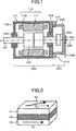
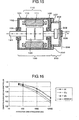
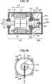
Die
Motoreinheit
Ein
Gestell umfasst einen zylindrischen Rahmen
Zwischen
dem Rahmen
Der
Stator
Wicklungsleiter,
die die Statorspule
Der
Rotor
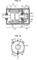
Nun
wird der Aufbau der Drehwinkel-Messeinheit
Die
Drehwinkel-Messeinheit
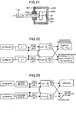
Der
Sensormagnet
Der
Magnetsensor
Der
Magnetsensor
Der
Magnetsensor
Es
genügt, dass der Magnetsensor
Die
Sensorverdrahtung
Der
Magnetsensor
Nun
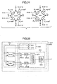
wird der Aufbau der Sensorelementeinheit
Wie
in
[Ausdruck 6][Expression 6]
-
ΔVc = V2 – V1 = –e0 G / 2R cosθ (6)ΔV c = V 2 -V 1 = -e 0 G / 2R cosθ (6)
Vorliegend
steht e0 für die Spannung, die
an die Anschlüsse e der in
[Ausdruck 7][Expression 7]
-
ΔVs = V2 – V1 = e0 G / 2R sinθ (7)ΔV s = V 2 -V 1 = e 0 G / 2R sinθ (7)
Als
Ergebnis führt das Verhältnis der SIN-Brückenausgabe
zur COS-Brückenausgabe zu tanθ, so dass die Ausrichtung θ des
Magnetfelds so bestimmt wird, dass [Ausdruck
8] ![]()
![]()
Die ArcTan-Funktion liefert ihre Ausgabe nur für den Winkelbereich von –90°~+90°. Wenn jedoch die an ΔVs und ΔVc angebrachten Vorzeichen entsprechend eingestellt werden, wie nachstehend beschrieben, kann die Ausrichtung θ über den gesamten Winkelbereich von 0~360° gemessen werden.The ArcTan function provides its output only for the angular range of -90 ° ~ + 90 °. However, when the signs attached to ΔV s and ΔV c are respectively set as described below, the orientation θ can be measured over the entire angle range of 0 ~ 360 °.
Nun
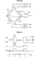
wird der Aufbau der Erfassungsschaltungseinheit
Es
wird hier bemerkt, dass die Ausgabeeinheit
Während der Zeitspanne, in der die GMR-Brücken nicht angeregt sind, das heißt, während der Zeit, in der die der Feldausrichtung θm entsprechende Sensorausgabe nicht erhalten wird, ist es nicht erforderlich, zu bestimmen, ob die Ausgabe der Ausgabeeinheit mit negativer Polarität negativer oder positiver als die Ausgabe der Ausgabeeinheit mit positiver Polarität ist. Beispielsweise wird in einem nachstehend beschriebenen Ausführungsbeispiel während der Zeitspanne, in der die Brücken von GMR-Elementen nicht angeregt sind, die Ausgabespannung der Ausgabeeinheit mit negativer Polarität gleich der Ausgabespannung der Ausgabeeinheit mit positiver Polarität gemacht.During the period in which the GMR bridges are not excited, that is, during the time in which the sensor output corresponding to the field orientation θ m is not obtained, it is not necessary to determine whether the output of the negative polarity output unit is more negative or more positive than the output of the positive polarity output unit. For example, in an embodiment described below, during the period in which the bridges of GMR elements are not excited, the output voltage of the negative polarity output unit is made equal to the output voltage of the positive polarity output unit.
Die
Signalverarbeitungseinheit
Der
Berechnungsvorgang der Winkelberechnungseinheit
Um
das vorstehende Problem (b) zu bewältigen, ermittelt die
Winkelberechnungseinheit 
Umgekehrt
wird, wenn |ΔVc| kleiner als |ΔVs| ist, die Feldausrichtung θ durch
den folgenden Ausdruck (10) berechnet. [Ausdruck
10] ![]()
![]()
Auf diese Weise kann verhindert werden, dass eine Berechnungsungenauigkeit, die sich daraus ergibt, dass der Nenner kleiner wird, groß wird.On this way, it is possible to prevent a calculation inaccuracy, which results from the fact that the denominator becomes smaller, becomes large.
Das obige Problem (a) wird wie folgt gehandhabt. Der Quadrant, in den θ fällt, wird in Abhängigkeit davon bestimmt, ob ΔVc oder ΔVs einen negativen oder positiven Wert annimmt [Quadrantbestimmung]. Die Kombination des bestimmten Quadranten mit den von den Ausdrücken (9) und (10) berechneten Werten ermöglicht es, den genauen Wert von θ über den gesamten Bereich von 0~360° zu berechnen.The above problem (a) is handled as follows. The quadrant into which θ falls is determined as a function of whether ΔV c or ΔV s assumes a negative or positive value [quadrant determination]. The combination of the particular quadrant with the values calculated from expressions (9) and (10) makes it possible to calculate the exact value of θ over the entire range of 0 ~ 360 °.
Durch
den vorstehend beschriebenen Ablauf wird die Ausrichtung θ des
Magnetfelds ermittelt. Wie jedoch später beschrieben wird,
fallen der Drehwinkel der Drehwelle
Wie später beschrieben wird, ist es mit einem Drehwinkel-Messgerät im Wesentlichen wichtig, zwischen dem Magnetfeldwinkel θm und dem Rotorwinkel θr zu unterscheiden.As will be described later, with a rotation angle measuring apparatus, it is substantially important to distinguish between the magnetic field angle θ m and the rotor angle θ r .
Um ein Drehwinkel-Messgerät mit hoher Genauigkeit zu realisieren, ist es notwendig, zu veranlassen, dass der Magnetfeldwinkel θm dem Rotorwinkel θr exakt entspricht. Wie dies geschieht, wird nachstehend beschrieben.In order to realize a rotation angle measuring apparatus with high accuracy, it is necessary to cause the magnetic field angle θ m to exactly correspond to the rotor angle θ r . How this happens is described below.
Nun
wird das Verfahren zum Korrigieren des Ausgabesignals des Magnetsensors
Die
Größe des Magnetsensors
Unter
Bezugnahme auf ![]()
![]()
Daher geschieht es, dass eine Ungenauigkeit δθm in dem Drehwinkel enthalten ist, der von dem Magnetfeldwinkel-Messgerät angegeben wird.Therefore, it happens that an inaccuracy δθ m is included in the rotation angle indicated by the magnetic field angle meter.
Typischerweise beträgt die Anbringungsungenauigkeit δx, die für den Magnetsensor mechanisch zu verursachen ist, 0,2 mm. Wenn die Länge L des Magnetsensors gleich 100 mm ist, wird die entsprechende Winkelungenauigkeit δθm 0,1°. Dieser Wert fällt in einen tolerierbaren Ungenauigkeitsbereich. Andererseits wird im Fall von L = 5 mm die entsprechende Winkelungenauigkeit δθm 2,3°. Dieses Ergebnis zeigt an, dass das im Gebrauch befindliche Magnetfeldwinkel-Messgerät von schlechter Genauigkeit ist.Typically, the mounting inaccuracy δx to be mechanically caused to the magnetic sensor is 0.2 mm. When the length L of the magnetic sensor is equal to 100 mm, the corresponding angular inaccuracy δθ m becomes 0.1 °. This value falls within a tolerable inaccuracy range. On the other hand, in the case of L = 5 mm, the corresponding angular inaccuracy δθ m becomes 2.3 °. This result indicates that the magnetic field angle measuring device in use is of poor accuracy.
Es
ist möglich, dass die Modullänge L eines Magnetsensors
Weiterhin besteht noch das Problem, dass die Erhöhung der Größe des Moduls in der Tat insofern vorteilhaft ist, dass die Toleranz der Anbringungsungenauigkeit erhöht werden kann, aber nicht zu dem Vorzug führt, dass der mit Magnetwiderstandselementen gebaute Magnetsensor von kleiner Größe und leichtem Gewicht sein kann.Farther There is still the problem that increasing the size of the module is indeed advantageous in that the tolerance the attachment inaccuracy can be increased, but not leads to the preference that with magnetic resistance elements built magnetic sensor of small size and lightweight Weight can be.
Der
Winkel θm des von dem Sensormagneten
Der
erste Grund, dass (1) der Ursprung (Nullpunkt) des Magnetfeldwinkels θm nicht mit dem Ursprung des Drehwinkels θ der
Drehwelle
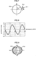
In
einem Fall, in dem (2) der Sensormagnet
Im
Allgemeinen ist ein Magnetfeld, das aus einem Magneten in der radialen
Richtung austritt, kein paralleles Feld. Wie beispielsweise in
[Ausdruck 12][Printout 12]
-
Hr(θ) = C(A1cosθ + A3cos3θ + A5cosθ + ...) (12)H r (θ) = C (A 1 cos θ + A 3 cos 3θ + A 5 cos θ + ...) (12)
[Ausdruck 13][Expression 13]
-
Hθ(θ) = A1sinθ + A3sin3θ + A5sin5θ + ... (13)H θ (θ) = A 1 sin θ + A 3 sin 3θ + A 5 sin 5θ + ... (13)
Dabei ist C eine Konstante, die ungefähr 1~2 gleich ist. In einem Fall, in dem die Harmoniekomponenten A3 und A5 beide gleich Null sind, d. h. A3 = A5 = 0, und in dem C = 1 ist, ist Hr = A1cosθ und Hθ = A1sinθ, was die Bedingung für ein paralleles Magnetfeld ergibt. In einem solchen Fall fällt der Magnetfeldwinkel θm mit dem Drehwinkel θr der Drehwelle zusammen.Where C is a constant that is about 1 ~ 2 equal. In a case where the harmonic components A 3 and A 5 are both equal to zero, ie A 3 = A 5 = 0, and where C = 1, H r = A 1 cosθ and H θ = A 1 sinθ, what gives the condition for a parallel magnetic field. In such a case, the magnetic field angle θ m coincides with the rotation angle θ r of the rotary shaft.
Vorliegend ist die Differenz δ des Magnetfeldwinkels θm von dem Drehwinkel θr der Drehwelle durch den folgenden Ausdruck definiert:In the present case, the difference δ of the magnetic field angle θ m from the rotational angle θ r of the rotary shaft is defined by the following expression:
[Ausdruck 14][Expression 14]
-
δ = θm – θr (14)δ = θ m - θ r (14)
Wenn eine Magnetisierungsungenauigkeit beim Magnetisieren des Sensormagneten vorliegt, wird die Entsprechung des Drehwinkels θr der Drehwelle zum Magnetfeldwinkel θm ungenau.When there is magnetization inaccuracy in magnetizing the sensor magnet, the correspondence of the rotation angle θ r of the rotation shaft to the magnetic field angle θ m becomes inaccurate.
[Verfahren zum Korrigieren eines Drehwinkel-Messgeräts][Method for Correcting a Rotation Angle Meter]
Wie unter Bezug auf die obigen Gründe (1)~(3) beschrieben ist, muss das Magnetfeld-Messgerät, das Magnetwiderstandselemente verwendet, eine solche physikalische Größe wie den Magnetfeldwinkel θm handhaben, und die physikalische Größe θm unterscheidet sich vom Drehwinkel θr des Sensormagneten. Es ist daher wichtig zu erkennen, dass eine Differenz zwischen ihnen in Abhängigkeit von einer bestimmten Bedingung auftreten kann. In dieser Beschreibung ist diese Differenz als δ definiert.As described with respect to the above reasons (1) ~ (3), the magnetic field measuring apparatus using magnetic resistance elements needs to handle such a physical quantity as the magnetic field angle θ m , and the physical quantity θ m is different from the rotation angle θ r of the sensor magnet. It is therefore important to realize that a difference between them can occur depending on a particular condition. In this description, this difference is defined as δ.
Mit
anderen Worten, solange der Magnetsensor
Ein konkreter Ablauf zum Bereitstellen der vorstehend beschriebenen Korrekturen wird nachstehend beschrieben.One specific procedure for providing the above-described Corrections will be described below.
Zuerst
ist, was (a) das korrekte Korrigieren des Magnetsensors betrifft,
eine Versatzkorrektur konkret wichtig. Es ist hier zu beachten,
dass es zwei Arten des Versatzes gibt: eine ist der Versatz für
den Magnetsensor, der den Abweichungen der Eigenschaften der den
Magnetsensor
In beiden Versatzabläufen wird die Versatzmenge dem Ausgabesignal des Magnetsensors überlagert. Dementsprechend wird das Verhältnis der SIN-Brückenausgabe zur COS-Brückenausgabe nicht gleich tanθ sein. Als Ergebnis kann der Magnetfeldwinkel θm nicht korrekt gemessen werden.In both offset sequences, the offset amount is superimposed on the output signal of the magnetic sensor. Accordingly, the ratio of the SIN bridge output to the COS bridge output does not become tanθ be. As a result, the magnetic field angle θ m can not be measured correctly.
Ein konkreter Ablauf zum Korrigieren des Versatzes ist die Einstellung der Versetzung der SIN-Brückenausgabe auf Null bei θm = 0 und die Einstellung des Versatzes der COS-Brückenausgabe auf Null bei θm = 90°.A concrete procedure for correcting the offset is to set the offset of the SIN bridge output to zero at θ m = 0 and to set the offset of the COS bridge output to zero at θ m = 90 °.
Für
diese Einstellung muss man den Ursprung für den Magnetfeldwinkel θm kennen. Jedoch ist es unmöglich,
den Ursprung aufgrund der Anbringungsungenauigkeit des Magnetsensors
In
diesem Ausführungsbeispiel wird der Ursprung für
den Magnetfeldwinkel durch ein nachstehend beschriebenes Verfahren
ermittelt. Das Verfahren ist als Flussdiagramm in
Zu
Beginn wird der Ursprung für den Drehwinkel θr der Drehwelle
Als
Nächstes wird die Drehwelle
Um die Beziehung zwischen θr' und θm über die N Drehungen der Welle zu kennen, muss man die Startposition der Drehung und die Endposition der Drehung kennen. Die Messung des Magnetfeldwinkels θm wird verwendet, um diese Information zu erfahren. Es genügt nämlich, dass die Messung fortgesetzt wird, bis ein Wert von θm, der der gleiche wie der Wert von θm ist, der am Beginn der Messung angenommen wurde, zuerst erreicht wird. Es ist zu beachten, dass, damit die Messung über N Drehungen durchgeführt wird, sie wiederholt werden sollte, bis der gleiche Wert für θm N-mal erscheint.To know the relationship between θ r 'and θ m over the N rotations of the shaft, one must know the start position of the rotation and the end position of the rotation. The measurement of the magnetic field angle θ m is used to find this information. Namely, it suffices that the measurement is continued until a value of θ m , which is the same as the value of θ m adopted at the beginning of the measurement, is first reached. It should be noted that in order to perform the measurement over N rotations, it should be repeated until the same value for θ m appears N times.
Nach der Messung der Beziehung zwischen θr' und θm wird die Differenz δ' durch den folgenden Ausdruck berechnet.After measuring the relationship between θ r 'and θ m , the difference δ' is calculated by the following expression.
[Ausdruck 15][Expression 15]
-
δ' = θm – θr' (15)δ '= θ m - θ r ' (15)
Auf
diese Weise kann die Differenz δ' als Funktion des Drehwinkels θr' ermittelt werden.
Was die Anzahl der Messdatenpunkte (δ', θr') betrifft, so genügt es, etwa einhundert von ihnen zu nehmen.As for the number of measurement data points (δ ', θ r '), it is sufficient to take about one hundred of them.
Als
Nächstes wird das gewichtete Mittel von δ' in
Bezug auf θr' wie folgt ermittelt. [Ausdruck
16] 
Da die tatsächlichen Messdaten (δ', θr') von diskreter Art sind, wird die integrale Berechnung durch den Ausdruck (16) tatsächlich durch kumulatives Zählen ersetzt.Since the actual measurement data (δ ', θ r ') is of a discrete type, the integral calculation is actually replaced by the expression (16) by cumulative counting.
Bei
dieser Datenabtastung wird die Drehwelle mit konstanter Geschwindigkeit
gedreht und wenn Daten (δ', θr')
in einem regelmäßigen Zeitabstand abgetastet werden,
sind daher die Abtastpunkte in Bezug auf θr'
gleich beabstandet. Daher kann der Ausdruck (16) als eine Formel
zum Berechnen des Mittels von δ' wie folgt vereinfacht
werden. [Ausdruck
17] ![]()
![]()
Daher ist es bevorzugt, die Drehwelle mit konstanter Geschwindigkeit zu drehen und die Datenpunkte (δ', θr') in regelmäßigem Zeitabstand abzutasten.Therefore, it is preferable to rotate the rotating shaft at a constant speed and to sample the data points (δ ', θ r ') at a regular interval.
Nun wird unter Verwendung der Werte von δ'av, die durch den Ausdruck (16) oder (17) ermittelt wurden, der Koordinatenpunkt des Drehwinkels wie folgt neu definiert.Now, using the values of δ ' av determined by the expression (16) or (17), the coordinate point of the rotation angle is redefined as follows.
[Ausdruck 18][Expression 18]
-
θrθr' – δ'av (18)θ r θ r '- δ' av (18)
[Ausdruck 19][Expression 19]
-
δ = θm – θr (19)δ = θ m - θ r (19)
Mit
dieser Definition ist die Beziehung zwischen δ und θr wie in
Auf
diese Weise fällt, wenn das gewichtete Mittel der Differenz δ Null
ist, der Ursprung für θr mit
dem Ursprung für θm zusammen.
Dieses Ergebnis liegt an der Symmetrie der Magnetfeldverteilung,
wie in
Nun
wird die Drehwelle an einem Drehwinkel θr = θm = 0 angehalten und eine Versatzeinstellung
wird auf eine solche Weise vorgenommen, dass das Ausgabesignal der
SIN-Brücke im Magnetsensor
Auf
diese Weise wird die Versatzeinstellung des Magnetsensors
Wie aus der vorstehenden Beschreibung ersichtlich, ist es wichtig, δ'av so genau wie möglich zu ermitteln, um zu bewirken, dass sich die Differenz zwischen dem Ursprung für θm und dem Ursprung für θr Null annähert. Gemäß diesem Verfahren wird, da der Wert von δ'av unter Verwendung aller Messdatenpunkte ermittelt wird, wie aus dem Ausdruck (6) oder (7) ersichtlich, der berechnete Wert kaum durch einzelne Messungenauigkeiten und Rauschen beim Messen beeinträchtigt. Somit können die beiden Ursprünge miteinander beinahe in Übereinstimmung gebracht werden.As apparent from the above description, it is important to determine δ ' av as accurately as possible in order to make the difference between the origin for θ m and the origin for θ r approach zero. According to this method, since the value of δ ' av is detected by using all the measurement data points as seen from the expression (6) or (7), the calculated value is hardly affected by individual measurement inaccuracies and noise in measurement. Thus, the two origins can be almost reconciled with each other.
Da die Zunahme bei der Drehanzahl N der Drehwelle zur Zunahme der Anzahl von Messdatenpunkten führt, wird der Einfluss von Messungenauigkeiten und Rauschen reduziert, um die Genauigkeit zu verbessern.There the increase in the number of rotations N of the rotary shaft for increasing the number of measurement data points, the influence of measurement inaccuracies becomes and reduces noise to improve accuracy.
Als
Nächstes wird nachstehend ein Verfahren zum (b) korrekten
Ermitteln der Beziehung zwischen dem Magnetfeldwinkel θm und dem Drehwinkel θr des
Sensormagneten
Da
die Versatzeinstellung des Magnetsensors
[Ausdruck 20][Expression 20]
-
θr = θm – δ (20)θ r = θ m - δ (20)
Nachstehend wird nun ein konkretes Verfahren beschrieben.below Now a concrete procedure is described.
Während
die Drehwelle
In diesem Ausführungsbeispiel werden 100 Messdatenpunkte (d. h. Abtastpunkte) für eine Umdrehung der Welle genommen. Je größer die Anzahl der Abtastpunkte, desto höher ist die Genauigkeit des ermittelten Drehwinkels θr. Andererseits wird, je größer die Anzahl der Abtastpunkte ist, der Speicherbereich in der Signalverarbeitungsschaltung, die Berechnungen zur Korrektur ausführt, desto mehr verbraucht. Daher sollte die Anzahl von Abtastpunkten auf einen geeigneten Wert eingestellt werden, um einen Kompromiss zwischen Genauigkeit und Speicherbelegung zu schaffen.In this embodiment, 100 measurement data points (ie sampling points) are taken for one revolution of the shaft. The greater the number of sampling points, the higher the accuracy of the determined rotational angle θ r . On the other hand, the larger the number of sampling points, the more the memory area in the signal processing circuit that performs computations for correction becomes more consumed. Therefore, the number of sample points should be set to an appropriate value to provide a trade-off between accuracy and memory occupancy.
Die
Differenz δ kann als Funktion des Rotorwinkels θr durch Berechnen jeweiliger Differenzen δ'
an einzelnen Datenpunkten (θr, θm) unter Verwendung des Ausdrucks (19) ermittelt
werden.
Durch Erhalten der Nachschlagetabelle für δ mit dem Magnetfeldwinkel θm als Index wird es infolgedessen möglich, die Differenzen δ' entsprechend den Magnetfeldwinkeln θm' zu berechnen, die aus tatsächlich gemessenen Datenpunkten berechnet sind. Dies ist der Hauptpunkt dieses Ausführungsbeispiels.As a result, by obtaining the look-up table for δ with the magnetic field angle θ m as the index, it becomes possible to calculate the differences δ 'corresponding to the magnetic field angles θ m ' calculated from actually measured data points. This is the main point of this embodiment.
Die
Nachschlagetabelle wird im Speicher der Signalverarbeitungseinheit
in dem Magnetsensor
Es folgt nun eine Beschreibung eines Verfahrens zum Verarbeiten von Signalen, wenn die Drehwinkel-Messeinheit arbeitet, das heißt, wenn der Drehwinkel gemessen wird.It Following is a description of a method for processing Signals when the rotation angle measuring unit is working, that is, when the angle of rotation is measured.
Zu
Beginn wird ein Magnetfeldwinkel θm auf
der Grundlage des Ausgabesignals des Magnetsensors 
Dann wird die Differenz δ, die dem berechneten θm entspricht, in Bezug auf die Nachschlagetabelle der Koordinaten (δ, θm) ermittelt. Wenn ein Wert gleich θm in der Nachschlagetabelle nicht gefunden werden kann, wird der erforderliche Wert von θm durch Interpolation aus nahen Werten ermittelt. Die Differenz δ, die dem interpolierten θm entspricht, wird so ermittelt. In diesem Ausführungsbeispiel wird der Linearinterpolationsablauf beim Interpolieren der Werte für θm eingesetzt. Der Linearinterpolationsablauf erfordert eine geringere Wiederholungsanzahl von Multiplikationen, die eine erhebliche Zeit für die Berechnung erfordern, und hat daher den Vorteil, dass eine Hochgeschwindigkeitsberechnung möglich ist.Then, the difference δ corresponding to the calculated θ m is determined with respect to the look-up table of the coordinates (δ, θ m ). If a value equal to θ m can not be found in the look-up table, the required value of θ m is determined by interpolation from near values. The difference δ corresponding to the interpolated θ m is thus determined. In this embodiment, the linear interpolation procedure is used in interpolating the values of θ m . The linear interpolation procedure requires a smaller number of repetitions of multiplications requiring a considerable time for the calculation, and therefore has the advantage that a high-speed calculation is possible.
Der Drehwinkel θr wird durch den Ausdruck θr = θm – δ erhalten.The rotation angle θ r is obtained by the expression θ r = θ m -δ.
Während die konventionellen Verfahren eine Messungenauigkeit von ungefähr ±10° beim elektrischen Winkel erlitten haben, kann das Verfahren gemäß dieser Erfindung eine solche Messungenauigkeit auf ±0,6° beim elektrischen Winkel senken, was eine Verbesserung der Messgenauigkeit bewirkt.While the conventional methods provide a measurement inaccuracy of about ± 10 ° electrical angle suffered, the process can according to this Invention such a measurement inaccuracy to ± 0.6 ° lower electrical angle, resulting in an improvement in measurement accuracy causes.
Es
sollte in diesem Ausführungsbeispiel bemerkt werden, dass
der Index in der Nachschlagetabelle nicht der Rotorwinkel θr, sondern der Magnetfeldwinkel θm ist. Der Grund dafür ist, dass
der Magnetfeldwinkel θm genau die
Größe ist, die von dem Magnetsensor
Die Nachschlagetabelle der Koordinaten (δ, θm), in der θm' in einem konstanten Intervall abgetastet werden, ermöglicht es, die Geschwindigkeit des Abrufens der Daten aus der Tabelle zu erhöhen und die Kapazität des Speichers, die der Tabelle gewidmet ist, zu verringern. Wie dies erreicht wird, wird nachstehend konkret beschrieben. In der folgenden Beschreibung ist der Index θm in der Tabelle als unabhängige Variable „x” beschrieben und der Wert (d. h. der Wert der Funktion) δ, auf den in der Tabelle Bezug genommen wird, ist mit „f(x)” bezeichnet.The look-up table of the coordinates (δ, θ m ) in which θ m 'is sampled at a constant interval makes it possible to increase the speed of fetching the data from the table and the capacity of the memory dedicated to the table reduce. How this is achieved will be specifically described below. In the following description, the index θ m in the table is an independent variable "X" and the value (ie, the value of the function) δ referred to in the table is denoted by "f (x)".
Es
sei angenommen, dass xmin = x[0] und xmax = x[Nmax], worin
xmin und xmax jeweils
der Minimal- und der Maximalwert der unabhängigen Variable
x sind, und dass das Intervall zwischen jenen Werten gleichmäßig
in Nmax Unterintervalle unterteilt ist.
Auch sei die Funktion, die die diskrete Version von f(x) ist, durch
fn[n] bezeichnet, und es ist definiert, dass f(x) = f(x[n]) = fn[n].
Dann wird für einen beliebigen Wert der unabhängigen
Variablen x ix durch den folgenden Ausdruck berechnet. [Ausdruck
22] 
Wenn der integre Teil und der Dezimalteil des erhaltenen Werts ix mit n bzw. r bezeichnet ist, folgt daraus, dass:If the integre part and the decimal part of the obtained value ix with n or r, it follows that:
[Ausdruck 23][Expression 23]
-
f(x) = fn[n] + r·(fn[n + 1] – fn[n]) (23)f (x) = fn [n] + r · (fn [n + 1] - fn [n]) (23)
Dieser Ausdruck dient zur Interpolation mit einer linearen Funktion (d. h. lineare Interpolation) unter Verwendung von fn[n] und fn[n + 1], die aus der Nachschlagetabelle ermittelt wird und die jeweils x[n] und x[n + 1] entspricht, die dem Wert der unabhängigen Variable x am nächsten sind.This Expression is for interpolation with a linear function (i.e. H. linear interpolation) using fn [n] and fn [n + 1], which is determined from the lookup table and the respective x [n] and x [n + 1] which corresponds to the value of the independent Variable x are closest.
Die Werte von „Nmax/(xmax – xmin)” im Ausdruck (22) werden vorab berechnet, wenn die Nachschlagetabelle eingerichtet wird, das heißt, wenn eine Korrektur vorgenommen wird, und die vorab berechneten Werte werden dann als Konstanten im Speicher der Verarbeitungseinheit gespeichert. Dadurch kann ein Teilungsvorgang in dem Vorgang eliminiert werden, der beim Betrieb des Drehwinkel-Messgeräts stattfindet. Eine Mikrosteuerung benötigt normalerweise eine lange Zeit für einen Teilungsvorgang und daher kann dieses Verfahren, das den Teilungsvorgang beseitigt, den Betrieb des Drehwinkel-Messgeräts sehr beschleunigen.The values of "N max / (x max -x min )" in expression (22) are calculated in advance when the look-up table is established, that is, when a correction is made, and the pre-calculated values are then stored in memory as constants the processing unit stored. Thereby, a dividing operation in the process taking place in the operation of the rotation angle measuring apparatus can be eliminated. A microcontroller normally takes a long time for a split operation, and therefore this method, which eliminates the split operation, can greatly accelerate the operation of the rotation angle meter.
Gemäß diesem Verfahren kann weiterhin, da die Stelle, die einem zugeteilten Wert von x entspricht, auf die in der Nachschlagetabelle Bezug zu nehmen ist, durch eine einzige Berechnung mit dem Ausdruck (22) spezifiziert werden kann, der Betrieb des Drehwinkel-Messgerät stark beschleunigt werden.According to this Procedures can continue, as the body assigns an assigned value x corresponds to referencing in the look-up table is specified by a single calculation with the expression (22) can be, the operation of the rotation angle meter strong be accelerated.
Da gemäß diesem Verfahren nur Daten, die in der Nachschlagetabelle gespeichert sind, fn[n] (n = 0~Nmax), xmin, xmax und Nmax/(xmax – xmin) sind und da Daten x[n] ((n = 0~Nmax) nicht gespeichert werden müssen, kann der Speicher zum Speichern von Daten eingespart werden.Since this process (N max n = 0 ~) x min, x max and N according to only data stored in the lookup table, fn [n] max / -, and since data x [n (x max x min) ] ((n = 0 ~ Nmax) need not be saved, the memory can be saved to save data.
Nun
wird das Verfahren zum Ermitteln des Drehwinkels θr der Drehwelle
Wie
aus
[Ausdruck 24][Expression 24]
-
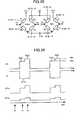
θr(t) = t / T ·360° (24) 121 eine Umdrehung ausführt (d. h. eine Zeitspanne). Die Zeitspanne T kann durch Bestimmen der zwei aufeinander folgenden Zeitpunkte ermittelt werden (wobei der frühere der Startpunkt der Drehung ist, d. h. t = 0), an welchen Zeitpunkten der Magnetsensor201 den gleichen Wert für den Magnetfeldwinkel θm erfasst.θ r (t) = t / T x 360 ° (24)rotary shaft 121 one revolution (ie one time span). The time T can be determined by determining the two consecutive times (the earlier being the starting point of the rotation, ie, t = 0), at which times themagnetic sensor 201 the same value for the magnetic field angle θ m detected.
Wenn
sich die Drehwelle
Sowohl
in
Nun
wird ein Fall betrachtet, in dem sich die Drehzahl im Lauf der Zeit
mit einer bekannten Geschwindigkeit ändert. Unter der Annahme,
dass die Änderungsrate A(t) der Drehzahl ω im
Lauf der Zeit variabel ist, sei angenommen, dass ω(t) = ω0·A(t) ist. In diesem Fall kann
der Drehwinkel θr(t) zum Zeitpunkt
t durch den folgenden Ausdruck berechnet werden. [Ausdruck
25] 
Beispielweise kann in einem Fall, in dem sich die Drehzahl mit konstanter Beschleunigung oder mit einer bekannten Geschwindigkeit (mit enthaltenen Welligkeiten) ändert, der Drehwinkel θr zum Zeitpunkt t durch Verwenden des Ausdrucks (25) ermittelt werden.For example, in a case where the speed of constant acceleration or a known speed (including ripples included) changes, the rotation angle θ r at time t can be obtained by using expression (25).
Gemäß diesem
Ausführungsbeispiel wird die Differenz δ unter
Verwendung des Magnetfeldwinkels θm, der
tatsächlich von dem Magnetsensor
In
dem Fall, in dem der Sensormagnet
Gemäß dieser Erfindung kann daher, wenn ein zweipoliger Magnet als Sensormagnet verwendet wird, ein großer Vorteil genutzt werden, da Faktoren für irgendeine Art von Ungenauigkeit, wie etwa eine Anbringungsungenauigkeit des Magneten und Sensors oder eine Magnetisierungsungenauigkeit des Magneten, korrigiert werden kann.According to this Invention can therefore, when a two-pole magnet as a sensor magnet Used to be a big advantage because factors for some kind of inaccuracy, such as an attachment inaccuracy of the magnet and sensor or a magnetization inaccuracy of the magnet, can be corrected.
Nun erfolgt eine Beschreibung eines Falls, in dem ein mehrpoliger Magnet als Sensormagnet eingesetzt wird. Es sei angenommen, dass der mehrpolige Magnet ein (2N)-Pol-Magnet mit N Sätzen von N-Polen und S-Polen ist. In diesem Fall führt eine Umdrehung des (2N)-Pol-Magnets zur Änderung des Magnetfeldwinkels über N Zeitspannen. Dabei soll jede Zeitspanne als ein Sektor bezeichnet werden. Dementsprechend kann man sagen, dass der (2N)-Pol-Magnet N Sektoren abdeckt.Now a description will be made of a case where a multi-pole magnet is used as a sensor magnet. It is assumed that the multipole Magnet a (2N) pole magnet with N sets of N poles and S Poland is. In this case, one turn of the (2N) pole magnet will result for changing the magnetic field angle over N time periods. Each period should be referred to as a sector. Accordingly, can it is said that the (2N) pole magnet covers N sectors.
Im Bereich von einem Sektor wird die einem Magnetfeldwinkel θm entsprechende Differenz δ eindeutig bestimmt. Dementsprechend ist, wenn ein (2N)-Pol-Magnet verwendet wird und wenn Magnetisierungsungenauigkeiten in verschiedenen Sektoren innerhalb eines vernachlässigbar kleinen Bereich fallen, das Korrekturverfahren gemäß dieser Erfindung wirksam.In the range of one sector, the difference δ corresponding to a magnetic field angle θ m is uniquely determined. Accordingly, when a (2N) pole magnet is used and when magnetization inaccuracies in various sectors fall within a negligibly small range, the correction method according to this invention is effective.
Weiterhin
wird auch in dem Fall, in dem der funktionsfähige Bereich
der Drehwelle
In
dem Fall, in dem ein mehrpoliger Magnet verwendet wird, dessen Magnetisierungsungenauigkeiten in
verschiedenen Sektoren nicht vernachlässigbar sind, wird
ein Drehpositionssensor, wie etwa ein optischer Kodierer, an der
Drehwelle
Da
der aktuelle Sektor aus dem Versatzbetrag des Drehwinkels berechnet
werden kann, kann die Information über den aktuellen Sektor
auch in der Erfassungsschaltungseinheit
Beispielsweise
ist in
Jedoch
wird gemäß diesem konventionellen Beispiel eine
Korrektur durch Ausdrücken der Beziehung zwischen dem Drehwinkel
der Drehwelle und der Ausgabespannung des Magnetwiderstandselements
durch einen Näherungsausdruck durchgeführt. In
diesem Fall muss der Näherungsausdruck komplex sein, wenn
die Beziehung zwischen dem Drehwinkel der Drehwelle und der Ausgabespannung
des Magnetwiderstandselements komplex wird, das heißt,
wenn die Beziehung zwischen δ und θm (nachstehend
als „δθm”-Verteilung” bezeichnet),
wie in den
Im Fall des Ausdrückens der Beziehung durch einen Näherungsausdruck, wenn die δθm-Verteilung eine komplexe Form annimmt, neigt der Näherungsausdruck dazu, eine relativ große Ungenauigkeit zu bewirken. Dieses Ausführungsbeispiel kann die δ-θm-Verteilung bewältigen, ungeachtet dessen, welche Form sie annimmt.In the case of expressing the relationship by an approximate expression, when the δθ m distribution takes a complex shape, the approximate expression tends to cause a relatively large inaccuracy. This embodiment can handle the δ-θ m distribution regardless of which shape it adopts.
Bei dieser Erfindung kann ein einfaches Verfahren zum Korrigieren der Magnetfeldverteilung zusätzlich verwendet werden. Es wird nämlich ein korrigierter Winkel θadj, der durch einen Korrigiervorgang behandelt worden ist, für den Magnetfeldwinkel θm in dem Schritt des Zusammenstellens der Nachschlagetabelle eingesetzt; die Differenz δ wird mittels des folgenden Ausdrucks berechnet:In this invention, a simple method for correcting the magnetic field distribution can additionally be used. Namely, a corrected angle θ adj , which has been treated by a correcting operation, is substituted for the magnetic field angle θ m in the step of composing the look-up table; the difference δ is calculated by the following expression:
[Ausdruck 26][Expression 26]
-
δ = θadj – θr (26) 201 gemessenen Magnetfeldwinkel θ berechnet, und danach wird ein korrekter Rotorwinkel θr mittels des Ausdrucks θr = θadf – δ erhalten.δ = θ adj - θ r (26) magnetic sensor 201 measured magnetic field angle θ, and thereafter a correct rotor angle θ r is obtained by the expression θ r = θ adf -δ.
Da die Differenz δ mittels des korrigierten Winkels θadj anstelle des Magnetfeldwinkels klein θm gemacht wird, verbessert sich die Genauigkeit bei der Korrektur. Weiterhin wird die Abhängigkeit vom Winkel der Differenz δ durch die Verwendung des korrigierten Winkels klein, so dass die Genauigkeit bei der Berechnung der Werte für die Differenz δ durch Interpolation verbessert wird, wodurch eine genaue Korrektur mit weniger Datenpunkten erfolgen kann. Dementsprechend wird die Anzahl von in der Nachschlagetabelle verwendeten Datenpunkten geringer und daher wird eine Korrektur mit weniger Speicherkapazität möglich.Since the difference δ by means of the corrected angle θ adj small θ m is taken instead of the magnetic field angle, the accuracy is improved in the correction. Further, the dependence on the angle of the difference δ becomes small by the use of the corrected angle, so that the accuracy in the calculation of the values for the difference δ is improved by interpolation, whereby an accurate correction can be made with fewer data points. Accordingly, the number of data points used in the look-up table becomes smaller, and therefore a correction with less storage capacity becomes possible.
Gemäß dem
in
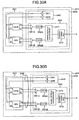
Es werden nun Einzelheiten beschrieben, wie in ein System in ein Drehwinkel-Messgerät eingebaut wird, das wie vorstehend beschrieben hergestellt ist. In diesem Ausführungsbeispiel ist ein Fall beispielhaft dargestellt, in dem ein Drehwinkel-Messgerät in einer elektrischen Servolenkungsvorrichtung eingebaut ist.It Now details are described, such as in a system in a rotation angle meter is incorporated, which is prepared as described above. In this embodiment, a case is exemplified, in which a rotation angle meter in an electric power steering apparatus is installed.
Nach
dem anfänglichen Einstellen des Systems auf den Winkelursprung
und Systemursprung wird der Drehwinkel θr0 der
Drehwelle
Selbst wenn es eine Anbringungsungenauigkeit beim Anbringen des Drehwinkel-Messgeräts im System gibt, kann die Anbringungsungenauigkeit korrigiert werden, wenn der Wert für den Drehwinkel θr0, der dem Systemursprung entspricht, bekannt ist.Even if there is an attachment inaccuracy in mounting the rotation angle meter in the system, the mounting inaccuracy can be corrected when the value for the rotation angle θ r0 corresponding to the system origin is known.
Die
normalerweise von einem System, wie etwa einem Servolenkungssystem,
erforderliche Information ist ein Systemwinkel θsys. Gemäß diesem Ausführungsbeispiel
kann ein solcher Systemwinkel θsys auf
der Grundlage des Magnetfeldwinkels θm,
der aus dem Ausgabesignal des Magnetsensors
Das
zweite Ausführungsbeispiel dieser Erfindung wird unter
Bezugnahme auf
Drehwinkelsensoren
leiden unter dem Problem, dass eine Temperaturänderung
eine Verschlechterung der Messgenauigkeit verursacht. Dies ist das
Problem einer schlechten Temperatureigenschaft. Gemäß diesem
Ausführungsbeispiel wird die Temperatureigenschaft des
Magnetsensors
Die
Ursache für die Verschlechterung der Temperatureigenschaft
in dem Magnetwiderstandselement liegt in der Überlagerung
von Versetzungs- bzw. Offsetspannungen auf die Ausgabesignale der
Sensorelementeinheit
Jedoch werden Offsetspannungen ΔVs und ΔVc in der tatsächlichen Brücke, die GMR-Elemente verwendet, überlagert, wie in den folgenden Ausdrücken (27) angegeben.However, offset voltages ΔV s and ΔV c are superimposed in the actual bridge using GMR elements as indicated in the following expressions (27).
[Ausdruck 27][Expression 27]
-
ΔVc = V2 – V1 = –e0 G / 2R cosθ + ΔVc(ofs) (27)ΔV c = V 2 -V 1 = -e 0 G / 2R cosθ + ΔV c (ofs) (27) -
ΔVs = V2 – V1 = e0 G / 2R sinθ + ΔVs(ofs)ΔV s = V 2 -V 1 = e 0 G / 2R sinθ + ΔV s (ofs)
Als Ergebnis ist das Verhältnis ΔVs/ΔVc nicht gleich tanθ, und selbst wenn das Verhältnis ΔVs/ΔVc erhalten wird, heben die GMR-Koeffizienten G/R des Zählers und Nenners einander nicht auf, so dass sich der Magnetfeldwinkel θm mit der Temperatur ändert.As a result, the ratio ΔV s / ΔV c is not equal to tanθ, and even if the ratio ΔV s / ΔV c is obtained, the GMR coefficients G / R of the numerator and denominator do not cancel each other, so that the magnetic field angle θ m with the temperature changes.
Selbst
wenn eine Versatzeinstellung bei Raumtemperaturen in einer Erfassungsschaltung
Der Grund, dass eine Offsetspannung in der Signalspannung ΔVc(ofs) erzeugt wird, liegt daran, dass die elektrischen Widerstände der vier die Brücke bildenden Elemente nicht demselben Wert bei θ = 90° (d. h. cosθ = 0) gleich gemacht sind, da die Eigenschaften der Elemente voneinander variieren.The reason that an offset voltage is generated in the signal voltage ΔV c (ofs) is because the electric resistances of the four elements constituting the bridge are not made equal to each other at θ = 90 ° (ie, cos θ = 0) because the Properties of the elements vary from each other.
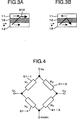
In
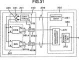
diesem Ausführungsbeispiel umfasst die COS-Brücke
in der Sensorelementeinheit
Die
aus den GMR-Elementen
Die
aus den GMR-Elementen
Die
Signalanschlüsse V1 und V2 sind mit einer Erfassungsschaltung
Das Merkmal dieses Ausführungsbeispiel besteht darin, dass die aus vier GMR-Elementen bestehende Brücke in zwei Halbbrücken geteilt wird und die beiden Halbbrücken von unterschiedlichen Spannungen e1 bzw. e2 betätigt werden. Mit dieser Schaltungskonfiguration wird es möglich, Offsetspannungen wie nachstehend beschrieben zu eliminieren.The feature of this embodiment is that the four GMR elements bridge is divided into two half bridges and the two half bridges of different voltages e 1 and e 2 are operated. With this circuit configuration, it becomes possible to eliminate offset voltages as described below.
Wie
in
Es
sei angenommen, dass die Magnetisierungsrichtungen der verstifteten
Magnetschichten
Die
Differenzspannung ΔV (= V2 – V1) zwischen den Anschlüssen 1 und
2 der Brückenschaltung in 
Die vorstehende Überlegung wird auf einen solchen allgemeinen Fall erstreckt, in dem andere Elemente als GMR-Elemente verwendet werden, wie nachstehend beschrieben. Es wird ein Fall betrachtet, in dem sich R1 und R3, die ein gegenüberliegendes Widerstandspaar in der Brücke bilden, wie folgt ändern (n = 1, 3):The above consideration is extended to such a general case where elements other than GMR elements are used, as described below. Consider a case where R 1 and R 3 forming an opposing pair of resistors in the bridge change as follows (n = 1, 3):
[Ausdruck 29][Print 29]
-
Rn = Rn0 + ΔR (29)R n = R + n0 .DELTA.R (29)
Es wird auch ein anderer Fall betrachtet, in dem sich R2 und R4, die das andere gegenüberliegende Widerstandspaar in der Brücke bilden, wie folgt ändern (n = 2, 4).Another case is considered in which R 2 and R 4 are opposite each other Make resistance pair in the bridge, change as follows (n = 2, 4).
[Ausdruck 30][Expression 30]
-
Rn = Rn0 – ΔR (30)R n = R n0 -ΔR (30)
Wenn ein konkreter Fall betrachtet wird, in dem GMR-Elemente verwendet werden, entspricht der Wert, der ermittelt wird, wenn der Magnetfeldwinkel θ gleich 90° ist, Rn0. Dies ist durch Vergleich der Ausdrücke (2) und (3) mit den Ausdrücken (29) und (30) klar ersichtlich.Considering a concrete case in which GMR elements are used, the value obtained when the magnetic field angle θ is equal to 90 ° corresponds to R n0 . This can be clearly seen by comparing expressions (2) and (3) with expressions (29) and (30).
Wenn ΔR
= 0, wird die Differenzspannung ΔV (= V2 – V1) zwischen den Anschlüssen 1 und
2 der Brücke in 
Da
dieser Wert für ΔR = 0 berechnet wird, ist er
als „ΔV0” definiert.
Dann wird ein ähnlicher Wert für ΔR ≠ 0
ermittelt. [Ausdruck
32] 
![]()
![]()
Der Zähler des ersten Terms im Ausdruck (32) ist der gleiche wie der entsprechende Zähler im Ausdruck (31). Wenn angenommen wird, dass ΔV0 = 0, ergibt dementsprechend der Ausdruck (32) die folgende Proportionalitätsbeziehung.The numerator of the first term in expression (32) is the same as the corresponding counter in expression (31). Accordingly, assuming that ΔV 0 = 0, the expression (32) gives the following proportionality relation.
[Ausdruck 34][Expression 34]
-
Δν = CΔR (34)Δν = CΔR (34)
Vorliegend ist der Proportionalitätsfaktor C das, was durch den Ausdruck (33) gegeben ist.present the proportionality factor C is what is meant by the expression (33) is given.
Wenn
der durch den Ausdruck (31) gegebene ΔV0 durch
Einstellen der Spannungsdifferenz (e2 – e1) gleich Null gemacht wird, wird die Signalspannung ΔV
der in
Der Hauptpunkt dieses Ausführungsbeispiel ist es, imstande zu sein, die Anregungsspannungen e1 und e2, die an die beiden Halbbrückenpaare angelegt werden, getrennt einzustellen. Um diesen Punkt klar zu machen, wird der Unterschied dieses Ausführungsbeispiels zu den konventionellen Beispielen nachstehend erläutert.The main point of this embodiment is to be able to separately adjust the excitation voltages e 1 and e 2 applied to the two half-bridge pairs. To make this point clear, the difference of this embodiment from the conventional examples will be explained below.
Im
Fall einer in
Nun
werden Temperatureigenschaften unter Bezug auf die Sensorelementenbrücke,
wie in
Die Temperatureigenschaft des Widerstands einer Substanz kann durch den folgenden Ausdruck dargestellt werden.The Temperature property of the resistance of a substance can through the following expression will be presented.
[Ausdruck 35][Expression 35]
-
R(T) = R(T0)[1 + a(T + T0)] = R(T0)(1 + aΔT) (35)R (T) = R (T 0 ) [1 + a (T + T 0 )] = R (T 0 ) (1 + aΔT) (35)
Die Einsetzung des Ausdrucks (35) in den Zähler des ersten Terms des Ausdrucks (32) und die Neuordnung des Ausdrucks (32) ergeben (1 + aΔT) als Multiplikationsfaktor. Wenn daher ΔV0 bei einer bestimmten Temperatur gleich Null gemacht wird, folgt daraus, dass ΔV0 = 0 bei irgendeiner anderen Temperatur ist.Substituting expression (35) into the numerator of the first term of expression (32) and rearranging expression (32) yields (1 + aΔT) as a multiplication factor. Therefore, if ΔV 0 is made zero at a certain temperature, it follows that ΔV 0 = 0 at any other temperature.
Gemäß diesem Ausführungsbeispiel ist nämlich, wenn die Spannungsdifferenz (e2 – e1) so eingestellt ist, dass ΔV0 = 0 bei einer bestimmten Temperatur ist, zum Beispiel bei einer Raumtemperatur, ΔV0 = 0 bei irgendeiner anderen Temperatur. Dies bedeutet, dass die durch den Ausdruck (34) gegebene Proportionalitätsbeziehung erhalten wird.Namely, according to this embodiment, when the voltage difference (e 2 -e 1 ) is set so that ΔV 0 = 0 at a certain temperature, for example, at a room temperature, ΔV 0 = 0 at any other temperature. This means that the proportionality relationship given by the expression (34) is obtained.
Somit kann ein von der Offsetspannung freies Signal über einen breiten Temperaturbereich erhalten werden.Consequently can be a signal free from the offset voltage via a wide temperature range can be obtained.
Gemäß diesem Ausführungsbeispiel kann auf diese Weise die Anzahl der Schritte des Prüfungs-/Einstellungsablaufs um ein großes Ausmaß gesenkt werden, da die Temperatureigenschaft eines Magnetfeld-Messgeräts nach der Herstellung bei einer bestimmten Temperatur allein, zum Beispiel bei einer Raumtemperatur, eingestellt werden kann.According to this Embodiment can in this way the number of Steps of the exam / recruitment process by a large Extent be lowered because the temperature characteristic of a Magnetic field measuring device after manufacture at a certain Temperature alone, for example at room temperature, adjusted can be.
Als Nächstes wird ein Magnetfeld-Messgerät, das GMR-Elemente verwendet, betrachtet. R1 und R2 werden gemäß dem Ausdruck (2) wie folgt dargestellt:Next, a magnetic field meter using GMR elements will be considered. R 1 and R 2 are represented by the expression (2) as follows:
[Ausdruck 36][Expression 36]
-
Rn = Rn0 – G / 2 cosθ (36)R n = R n0 - G / 2 cos θ (36)
Im Vergleich mit dem Ausdruck (29) wird das Differenzspannungssignal im Fall der Verwendung von GMR-Elementen durch den folgenden Ausdruck bezeichnet.in the Comparison with the expression (29) becomes the differential voltage signal in the case of using GMR elements by the following expression designated.
[Ausdruck 37][Expression 37]
-
Δν = – CG / 2 cosθ (37)Δν = - CG / 2 cosθ (37)
Es kann nämlich ein Signal erhalten werden, das proportional zum Kosinus der Magnetfeldausrichtung θ ist. Das so erhaltene Signal wird mit ΔVc bezeichnet.Namely, a signal proportional to the cosine of the magnetic field orientation θ can be obtained. The signal thus obtained is designated by ΔV c .
Die Konstante C ist der Wert, der aus dem Ausdruck (33) ermittelt wird.The Constant C is the value obtained from expression (33).
In
dem Drehwinkel-Messgerät gemäß diesem
Ausführungsbeispiel ist der Aufbau der Motoreinheit
Gemäß diesem Ausführungsbeispiel kann die Temperatureigenschaft verbessert werden; die genaue Messung des Rotorwinkels kann aufgrund der Korrektur des Magnetfelds bewirkt werden; und daher kann ein Drehwinkel-Messgerät mit hoher Präzision über einen breiten Temperaturbereich hinweg realisiert werden.According to this Embodiment can improve the temperature characteristic become; The exact measurement of the rotor angle may be due to the correction the magnetic field are effected; and therefore, a rotation angle meter with high precision over a wide temperature range be realized away.
Gemäß diesem
Ausführungsbeispiel kann, da die Messung des Rotorwinkels über
einen breiten Temperaturbereich hinweg einfach durch Einstellen
der Vorspannung (Δe = e1 – e2) für die Erfassungsschaltungseinheit
Als
Nächstes wird das dritte Ausführungsbeispiel dieser
Erfindung beschrieben, in dem eine Offsetspannung reduziert werden
kann, die der Schaltungskonfiguration der Erfassungsschaltungseinheit
Dieses
Ausführungsbeispiel wird unter Bezugnahme auf
Gemäß diesem Ausführungsbeispiel wird das Magnetfeld genau erfasst, indem eine Offsetspannung eliminiert wird, die einer Erfassungsschaltung zugeschrieben werden kann.According to this Embodiment, the magnetic field is detected accurately, by eliminating an offset voltage associated with a detection circuit can be attributed.
Zum Zeitpunkt t1 wird eine Referenzspannung Vag an beide Anschlüsse Ve(i) und Vg(i) (i = 1, 2) angelegt. Dementsprechend werden der Anschluss e1 mit positiver Polarität und der Anschluss g1 mit negativer Polarität der Brücke beide auf der gleichen Spannung Vag gehalten und daher erzeugen beide Anschlüsse V1 und V2 die Signalspannung Vag, so dass das Differenzspannungssignal ΔV = V2 – V1 auf Null reduziert wird.At time t 1 , a reference voltage V ag is applied to both terminals V e (i) and V g (i) (i = 1, 2). Accordingly, the positive polarity terminal e 1 and the negative polarity terminal g 1 of the bridge are both kept at the same voltage V ag , and therefore both terminals V 1 and V 2 generate the signal voltage V ag , so that the differential voltage signal ΔV = V 2 - V 1 is reduced to zero.
Infolgedessen
ist der spontane Wert Vdet(t1)
zum Zeitpunkt t1 der Ausgangsspannung Vdet(t) der Erfassungsspannung
Das
Differenzsignal ΔVdet = Vdet(t2) – Vdet(t1), das zwischen
den Zeitpunkten t1 und t2 berechnet
wird, wird zu einer Signalspannung, die frei von der Offsetspannung
ist, die der Erfassungsschaltung
In gleicher Weise ist das Differenzsignal ΔVdet = Vdet(t4) – Vdet(t3) eine Signalspannung zum Zeitpunkt t4.In the same way, the difference signal ΔV det = V det (t 4 ) -V det (t 3 ) is a signal voltage at time t 4 .
Gemäß diesem
Ausführungsbeispiel besteht auf diese Weise der wesentliche
Punkt darin, die vier Anschlüsse e1,
e2, g1 und g2 der Brücke der
Weiterhin wird gemäß diesem Ausführungsbeispiel zuerst das Referenzsignal Vdet(t1) gemessen, dann wird die Signalspannung Vdet(t2) zum Anregen der GMR-Elemente ermittelt und schließlich wird die Signalspannung ΔVdet = Vdet(t2) – Vdet(t1) ermittelt. Diese Verfahrensreihenfolge minimiert die Zeitverzögerung zwischen dem Ausgangssignal zur Zeit der Signalmessung (d. h. Abtastung) und dem Ausgangssignal nach der Signalverarbeitung. Diese Gestaltung ist insbesondere bei einer Anwendung bei einer Magnetfelderfassungsschaltung wichtig, die für die Messung von beispielsweise dem Drehwinkel einer Motorwelle verwendet werden kann, welche Hochgeschwindigkeitsreaktionen erfordert.Further, according to this embodiment, first the reference signal V det (t 1 ) is measured, then the signal voltage V det (t 2 ) for exciting the GMR elements is detected and finally the signal voltage ΔV det = V det (t 2 ) - V det (t 1 ) determined. This process order minimizes the time delay between the output signal at the time of signal measurement (ie, sampling) and the output signal after the signal processing. This configuration is particularly important in an application to a magnetic field detection circuit that can be used for measuring, for example, the rotation angle of a motor shaft that requires high-speed reactions.
In
diesem Ausführungsbeispiel werden die GMR-Elemente für
eine Stromführung nur während der Zeitspanne angeregt,
wenn der Impuls
Da die in den GMR-Elementen verbrauchte elektrische Leistung gesenkt werden kann, kann gemäß diesem Ausführungsbeispiel die Wärmeerzeugung (Joule-Wärme) durch die GMR-Elemente verringert werden und daher kann der Vorteil genutzt werden, dass die Änderung der Eigenschaften der GMR-Elemente aufgrund des Temperaturanstiegs unterdrückt werden kann.There lowered the electrical power consumed in the GMR elements can be according to this embodiment the heat generation (joule heat) by the GMR elements be reduced and therefore the advantage can be used that the change of properties of GMR elements due the temperature rise can be suppressed.
Weiterhin
sind gemäß diesem Ausführungsbeispiel
die Spannungsamplituden des Impulses
Nun
wird das vierte Ausführungsbeispiel dieser Erfindung unter
Bezugnahme auf
Wie
in
Wie
vorstehend beschrieben, erzeugen die ungleichen Eigenschaften der
GMR-Elemente eine Signaloffsetspannung, die die Verschlechterung
von Temperatureigenschaften des Magnetsensors
Daher
wird gemäß diesem Ausführungsbeispiel
die Anlegung der Anregungsspannung an die COS-Brücke im
Lauf der Zeit von der Anlegung der Anregungsspannung an die SIN-Brücke
verschoben, so dass Verdrahtungsleiter zwischen den Brücken
geteilt werden können und dass die Anzahl von Anschlüssen, die
aus der Sensorelementeinheit
Als
Ergebnis dieser versetzten Anlegung von Impulsen ändern
sich die Signalspannung ΔVc für
die COS-Brücke und die Signalspannung ΔVs für die SIN-Brücke, wie
in
Da
das Signal unter der Bedingung gemessen wird, dass die optimalen
Anregungsspannungen ΔV an die COS- bzw. SIN-Brücke
angelegt werden, kann dann auf diese Weise die Versatzkomponente,
die andernfalls in der Signalspannung enthalten sein kann, eliminiert
werden. Demgemäß kann, wie in dem zweiten Ausführungsbeispiel
beschrieben, ein Magnetsensor
Obwohl
der Aufbau der Sensorelementeinheit
Nun
wird das fünfte Ausführungsbeispiel dieser Erfindung
unter Bezugnahme auf
In diesem Ausführungsbeispiel ist ein Magnetsensor auf der Außenfläche des Gestells eines Drehwinkel-Messgeräts angebracht. Mit diesem Aufbau kann der Magnetsensor leicht angebracht werden. Da es nicht notwendig ist, die Verdrahtungsleiter für den Magnetsensor vom Inneren des Gestells des Drehwinkel-Messgeräts herauszuführen, kann weiterhin die Montage und Herstellung eines Drehwinkel-Messgeräts insbesondere für einen wasserdichten Aufbau vereinfacht werden.In This embodiment is a magnetic sensor on the Outer surface of the frame of a rotation angle measuring device appropriate. With this structure, the magnetic sensor can be easily mounted become. Since it is not necessary to use the wiring conductors for the magnetic sensor from the inside of the frame of the rotation angle measuring device can continue to lead the assembly and manufacturing a rotation angle measuring device in particular for a waterproof construction can be simplified.
Das
Drehwinkel-Messgerät dieses Ausführungsbeispiels
besteht hauptsächlich aus einer Motoreinheit
Die
Drehwinkel-Messeinheit
In
diesem Ausführungsbeispiel weist die Drehwinkel-Messeinheit
einen wasserdichten Aufbau auf. Dementsprechend ist ein Dichtungsmittel
Durch Einfügen von Dichtungsmitteln zwischen Elemente, die eine wasserdichte Grenze bilden, wird ein solcher Aufbau bereitgestellt, der das Eindringen von Wasser in einen Raum verhindern kann, der von den Elementen begrenzt wird. Daher muss in einem Fall, in dem Verdrahtungsleiter durch die wasserdichte Grenze gezogen werden müssen, ein mit Harz geformter Verbinder als die wasserdichte Grenze dienen, so dass eine elektrische Verbindung zwischen dem Inneren und dem Äußeren der Grenze durch Verbinden von Verdrahtungsleitern mit dem Verbinder bereitgestellt werden kann.By Inserting sealants between elements that have a form a watertight boundary, such a construction is provided, which can prevent the ingress of water into a room that is limited by the elements. Therefore, in a case where Wiring conductors are pulled through the watertight border need a resin molded connector than the waterproof one Serve a border, allowing an electrical connection between the Inside and outside of the border by joining be provided by wiring conductors with the connector can.
Der
Magnetsensor
Da
sich das Gehäuse
Für
das Gehäuse
Manchmal ist es bevorzugt, Metall als Material für das Gehäuse zu verwenden. Dies liegt daran, dass Metall mechanisch stärker und leichter zu verarbeiten ist als Harz. Wenn Metall für das Gehäuse verwendet wird, muss zusätzlich zu der Anforderung nach der magnetischen Suszeptibilität eine Einschränkung berücksichtigt werden. Denn es muss das Magnetfeld, das im Lauf der Zeit variabel ist, erfasst werden.Sometimes it is preferred to use metal as the material for the housing to use. This is because metal is mechanically stronger and easier to process than resin. If metal for The housing used must be in addition to the requirement for the magnetic susceptibility Restriction be considered. Because it has to the magnetic field, which is variable over time, are detected.
Da
die Drehung der Drehwelle 
Der
folgende Ausdruck, der die Dicke t (in Meter) jenes Teils des Gehäuses 
Die
Dicke t des Gehäuses
Alternativ
beträgt, wenn Np = 4 (im Fall eines
8-poligen Magneten), die Drehfrequenz gleich 15.000 UpM ist und
Messing, d. h. eine Cu(65%)-Zn(35%)-Legierung (Spezifischer Widerstand ρ =
6 × 10⁻⁸ Ωm),
als Material für das Gehäuse
Wenn
das im Lauf der Zeit variierende Magnetfeld durch eine Substanz
hindurchgeht, erzeugen freie Elektronen in der Substanz Wirbelströme,
was die Intensität des durch die Substanz hindurchgehenden
Magnetfelds dämpft.
Die
obige Beschreibung schlussfolgert, dass die Dicke jenes Teils des
Gehäuses
In
diesem Ausführungsbeispiel wird auf der Grundlage der obigen
Analyse Aluminium als Material für das Gehäuse
Weiterhin
ist es, wie in
Nun wird das sechste Ausführungsbeispiel dieser Erfindung beschrieben.Now The sixth embodiment of this invention will be described.
Das
in diesem Ausführungsbeispiel verwendete Drehwinkel-Messgerät
ist das gleiche wie dasjenige, das in
Bei
diesem Drehwinkel-Messgerät ist der Magnetsensor
In einem solchen Fall kann gemäß einem konventionellen Verfahren, bei dem ein Drehwinkel-Messgerät in ein System eingebaut wird, nachdem es von einem Korrekturaktuator/-kodierer korrigiert worden ist, das so eingebaute Drehwinkel-Messgerät den Drehwinkel θr nicht korrekt messen.In such a case, according to a conventional method in which a rotation angle measuring device is installed in a system after being corrected by a correction actuator / encoder, the thus installed rotation angle measuring device can not correctly measure the rotation angle θ r .
Gemäß diesem
Ausführungsbeispiel misst das Drehwinkel-Messgerät,
das bereits in ein beteiligtes System eingebaut worden ist, die
Entsprechung von θr zu θm, während die Drehwelle
Gemäß diesem Ausführungsbeispiel wird auf diese Weise, da der Korrekturablauf durchgeführt wird, während das Drehwinkel-Messgerät in das beteiligte System eingebaut ist, selbst dann, wenn sich die räumliche Verteilung des Magnetfelds aufgrund des Einflusses des nahen Magnetmaterialkörpers ändert, die Entsprechung von θr zu θm in einer solchen geänderten Verteilung des Magnetfelds gemessen. Dementsprechend kann der Drehwinkel θr auch in einem korrigierten System korrekt gemessen werden.In this embodiment, therefore, since the correction process is performed while the rotation angle meter is installed in the involved system, even if the spatial distribution of the magnetic field changes due to the influence of the nearby magnetic material body, the correspondence of θ r will increase θ m measured in such a changed distribution of the magnetic field. Accordingly, the rotation angle θ r can be correctly measured even in a corrected system.
Es
wird nun das siebte Ausführungsbeispiel dieser Erfindung
unter Bezugnahme auf
Der
Aufbau einer Motoreinheit
Eine
Drehwinkel-Messeinheit
Das
Merkmal dieses Ausführungsbeispiels ist, dass die Drehwinkel-Messeinheit
Der
Magnetschirmeffekt wird durch Abdecken der Drehwinkel-Messeinheit
Materialien mit einer magnetischen Suszeptibilität χ von mindestens 100 schließen weiches Eisen (χ = 2000), Eisen (χ = 5000), Siliciumstahl (χ = 7000), Mu-Metall (χ = 100.000) usw. ein. In diesem Ausführungsbeispiel wird Eisen verwendet.materials with a magnetic susceptibility χ of at least 100 close soft iron (χ = 2000), iron (χ = 5000), silicon steel (χ = 7000), Mu metal (χ = 100,000) and so on. In this embodiment Iron is used.
Material
mit einer magnetischen Suszeptibilität von höchstens
0,01 wird für das Gehäuse
Ein
wasserdichter Aufbau wird durch Einfügen eines Dichtungsmittels
Der
Magnetsensor
Da
sich der Magnetsensor
Durch
die Abdeckung
Weiterhin
werden gemäß diesem Ausführungsbeispiel
Löcher für eine Wasserdrainage in drei Positionen
geschaffen, wie
Wenn
die aus einem Material mit hoher Permeabilität bestehende
Abdeckung
In
einem solchen Fall sollte nach dem Anbringen der Abdeckung
Da die äußere Umgebung, wo das Drehwinkel-Messgerät platziert ist, nur einen ausreichend kleinen Einfluss auf die Verteilung des Magnetfelds ausübt, kann gemäß diesem Ausführungsbeispiel eine ausreichende Messgenauigkeit ohne Neukorrektur sichergestellt werden, die andernfalls nach der Installation des Drehwinkel-Messgeräts vorgenommen werden könnte.There the external environment where the rotation angle meter is placed, only a small enough influence on the distribution of the magnetic field can, according to this Embodiment sufficient measurement accuracy without Reconcile will be ensured, otherwise after installation the angle of rotation measuring device could be made.
Nachstehend
wird das achte Ausführungsbeispiel dieser Erfindung unter
Bezugnahme auf
Der
Aufbau einer Motoreinheit
Der
Aufbau einer Drehwinkel-Messeinheit
Da die Verteilung des Magnetfelds entlang der Mittellinie des Drehwinkels des Sensormagneten fast parallel ist, kann der Vorteil genutzt werden, dass das Korrekturausmaß des Magnetfelds verringert werden kann.There the distribution of the magnetic field along the center line of the rotation angle of the sensor magnet is almost parallel, the advantage can be used that the correction amount of the magnetic field can be reduced.
Da
der Magnetsensor
(DREHZAHL-MESSGERÄT)(SPEED MEASURING DEVICE)
Nachstehend
wird das neunte Ausführungsbeispiel dieser Erfindung unter
Bezugnahme auf
Dieses
Ausführungsbeispiel umfasst eine Drehwelle
Das
Gehäuse
Der
Magnetsensor
Der
Magnetsensor
Die
Zeitableitung der Signalspannung Vx ist
wie folgt. [Ausdruck
40] 
Daher
wird die Drehzahl ω = dθm/dt
des Magnetfeldwinkels θm wie folgt
erhalten. [Ausdruck
41] 
In
gleicher Weise kann die Zeitableitung der Signalspannung Vy der SIN-Brücke die Drehzahl wie
folgt ergeben. [Ausdruck
42] ![]()
![]()
Auf diese Weise wird die Drehzahl des Magnetfeldwinkels θm erhalten. Dieser Ablauf weist Merkmale auf, wie nachstehend beschrieben.In this way, the rotational speed of the magnetic field angle θ m is obtained. This process has features as described below.
Zuerst kann die Drehzahl ermittelt werden, ohne auf den Ablauf zurückzugreifen, bei dem eine ArcTan-Funktion (Arc-Tangens-Verfahren) verwendet wird. Außerdem kann, da die Proportionalitätskonstante B, die in den Signalspannungen beinhaltet ist, aufgehoben wird, die Drehzahl nur durch die Teilung der Zeitableitung von Vx durch Vy ermittelt werden. Wogegen eine Berechnung unter Verwendung der ArcTan-Funktion gewöhnlich viel Berechnungszeit benötigt, kann das Verfahren gemäß diesem Ausführungsbeispiel; das sich nicht auf die ArcTan-Funktion verlassen muss, ein Drehzahl-Messgerät realisieren, das bei Hochgeschwindigkeitsmessungen angewendet werden kann.First, the speed can be determined without resorting to the operation using an ArcTan (Arc Tangency) function. In addition, since the constant of proportionality B included in the signal voltages is canceled, the speed can be determined only by dividing the time derivative of V x by V y . While calculation using the ArcTan function usually requires a lot of computation time, the method according to this embodiment can; not relying on the ArcTan feature, realizes a speed meter that can be used in high-speed measurements.
Zweitens, obwohl die Ausdrücke (41) und (42) unterschiedliche Signalverarbeitungen durchführen, sind die Ergebnisse beider Verfahren einander gleich, das heißt, die Drehzahl des Magnetfeldwinkels θm. Daher müssen ωm1 und ωm2 den gleichen Wert annehmen. Mit anderen Worten, wenn sie unterschiedliche Werte annehmen, zeigt dies eine anormale Bedingung an, die im Drehzahl-Messgerät stattfindet.Second, although the expressions (41) and (42) perform different signal processing, the results of both methods are equal to each other, that is, the rotational speed of the magnetic field angle θ m . Therefore, ω m1 and ω m2 must assume the same value. In other words, if they take different values, this indicates an abnormal condition that occurs in the speed meter.
Konkret gesagt, es wird unter Berücksichtigung der Messgenauigkeit ein Fehlererfassungssignal nur dann erzeugt, wenn die Differenz zwischen dem einen Wert und dem anderen Wert außerhalb eines bestimmten Wertebereichs fällt.Concrete said, it is taking into account the measurement accuracy generates an error detection signal only when the difference between one value and the other value outside of a certain range of values.
Zur gleichen Zeit wird die Differenz zwischen ωm1 und ωm2 berechnet, und wenn die Differenz einen bestimmten festgelegten Wert ε überschreitet, wird ein Fehlererfassungssignal ausgegeben.At the same time, the difference between ω m1 and ω m2 is calculated, and when the difference exceeds a certain set value ε, an error detection signal is output.
Die
vorstehende Beschreibung ist dem Drehzahl-Messgerät gewidmet,
aber die Kombination des Drehzahl-Messgeräts und einem
der Drehwinkel-Messgeräte der obigen Ausführungsbeispiele
wird gleichermaßen nützlich sein. Konkret gesagt,
kann das Signalverarbeitungsverfahren, wie in
Weiterhin
ist eine andere Konfiguration ebenfalls nützlich, in der
nur die Fehlererfassungsfunktion, die in dem Verfahren, das in
Das
elfte Ausführungsbeispiel dieser Erfindung wird unter Bezugnahme
auf
Die Verarbeitungsschaltungen bestehen aus Differenzierungsschaltungen und Teilungsschaltungen, die alle mit analogen Komponenten aufgebaut sind, und der Fehlererfassungsvorgang wird von einem Komparator durchgeführt.The processing circuits consist of differentiating circuits and dividing circuits, all of which are constructed with analog components, and the error detecting operation is performed by a Kom parator performed.
Gemäß diesem Ausführungsbeispiel kann eine Echtzeitverarbeitung bewirkt werden, da die Verarbeitungsschaltung allein mit analogen Komponenten realisiert werden kann. Da keine Mikrosteuerung benötigt wird, wird außerdem ein Drehwinkel-Messgerät bereitgestellt, das gegen Umwelteinflüsse, wie etwa hohe Temperaturen, immun ist.According to this Embodiment can cause real-time processing be because the processing circuit alone with analog components can be realized. Since no microcontroller is needed, In addition, a rotation angle measuring device is provided, that against environmental influences, such as high temperatures, is immune.
Das
zwölfte Ausführungsbeispiel dieser Erfindung wird
unter Bezugnahme auf
Dieses
Ausführungsbeispiel ist das gleiche wie das vorstehend
beschriebene erste Ausführungsbeispiel, ausgenommen, dass
die Position der Erfassungsschaltungseinheit
Im
ersten Ausführungsbeispiel sind die Sensorelementeinheit
Dagegen
ist in diesem zwölften Ausführungsbeispiel, wie
in
In
diesem Ausführungsbeispiel ist die Erfassungsschaltungseinheit
Andererseits
jedoch kann die Motoreinheit
Das
Drehwinkel-Messgerät dieses Ausführungsbeispiels
umfasst die in
Die
Erfassungsschaltungseinheit
Die
in
Vorstehend
ist ein Beispiel beschrieben, in dem die Erfassungsschaltungseinheit
Auch
im Fall des fünften Ausführungsbeispiels, in dem
der Magnetsensor
Der
Grund für diese Nützlichkeit ist, dass die Erfassungsschaltungseinheit
Die
Erfassungsschaltungseinheit
Der
Magnetsensor
Die
von der Sensorelementeinheit
Mit
dieser Konfiguration wird das Signal von der ersten Sensorelementeinheit
Drei
Beispiele der Aufbauten für den Magnetsensor
Es
muss auch nicht erwähnt werden, dass die Konfiguration,
in der die Erfassungsschaltungseinheit
In dieser gesamten Beschreibung der vorliegenden Erfindung hindurch erfolgt die Beschreibung mit Riesen-Magneto-Widerstandselementen (GMR-Elementen), die für die Magnetwiderstandselemente zum Zweck des Messens eines Magnetfelds verwendet werden. Weiterhin beinhalten die Magnetwiderstandselemente anisotrope Magnetwiderstandselemente. Daher kann man sagen, dass ein Drehwinkel-Messgerät, das anisotrope Magnetwiderstandselemente verwendet, in den Umfang der vorliegenden Erfindung fällt.In throughout this description of the present invention the description is made with giant magnetoresistive elements (GMR elements) used for the magnetic resistance elements be used for the purpose of measuring a magnetic field. Farther The magnetic resistance elements include anisotropic magnetic resistance elements. Therefore, it can be said that a rotation angle meter that is anisotropic Magnetic resistance elements used, within the scope of the present Invention falls.
Es sollte von den Fachleuten auf dem Gebiet weiterhin verstanden werden, dass die vorstehende Beschreibung zwar an Ausführungsbeispielen der Erfindung erfolgt, die Erfindung aber nicht darauf beschränkt ist und verschiedene Änderungen und Modifikationen vorgenommen werden können, ohne vom Konzept der Erfindung und dem Umfang der beigefügten Ansprüche abzuweichen.It should continue to be understood by those skilled in the art, Although the above description of exemplary embodiments The invention is, but the invention is not limited thereto and made various changes and modifications without departing from the concept of the invention and the scope of the appended claims.
ZITATE ENTHALTEN IN DER BESCHREIBUNGQUOTES INCLUDE IN THE DESCRIPTION
Diese Liste der vom Anmelder aufgeführten Dokumente wurde automatisiert erzeugt und ist ausschließlich zur besseren Information des Lesers aufgenommen. Die Liste ist nicht Bestandteil der deutschen Patent- bzw. Gebrauchsmusteranmeldung. Das DPMA übernimmt keinerlei Haftung für etwaige Fehler oder Auslassungen.This list The documents listed by the applicant have been automated generated and is solely for better information recorded by the reader. The list is not part of the German Patent or utility model application. The DPMA takes over no liability for any errors or omissions.
Zitierte PatentliteraturCited patent literature
- - JP 3799270 [0002, 0189, 0194] - JP 3799270 [0002, 0189, 0194]
- - JP 2008-11661 A [0019, 0019] - JP 2008-11661 A [0019, 0019]
- - JP 2008-151774 A [0122] - JP 2008-151774 A [0122]
Claims (26)
Applications Claiming Priority (2)
| Application Number | Priority Date | Filing Date | Title |
|---|---|---|---|
| JP2009-144863 | 2009-06-18 | ||
| JP2009144863A JP5263024B2 (en) | 2009-06-18 | 2009-06-18 | Rotation angle detection device and rotation speed detection device |
Publications (1)
| Publication Number | Publication Date |
|---|---|
| DE102010003475A1 true DE102010003475A1 (en) | 2011-01-13 |
Family
ID=43307936
Family Applications (1)
| Application Number | Title | Priority Date | Filing Date |
|---|---|---|---|
| DE102010003475A Ceased DE102010003475A1 (en) | 2009-06-18 | 2010-03-30 | TURNING ANGLE MEASURING UNIT AND SPEED METER |
Country Status (4)
| Country | Link |
|---|---|
| US (1) | US8471552B2 (en) |
| JP (1) | JP5263024B2 (en) |
| CN (1) | CN101929834B (en) |
| DE (1) | DE102010003475A1 (en) |
Cited By (3)
| Publication number | Priority date | Publication date | Assignee | Title |
|---|---|---|---|---|
| EP2485374A1 (en) * | 2011-02-04 | 2012-08-08 | Dr. Fritz Faulhaber GmbH & Co. KG | Miniature electric motor |
| US8896163B2 (en) | 2011-02-04 | 2014-11-25 | Dr. Fritz Faulhaber Gmbh & Co. Kg | Electric micromotor |
| DE102017204415A1 (en) | 2017-03-16 | 2018-09-20 | Robert Bosch Gmbh | EC motor with an annular sensor magnet |
Families Citing this family (68)
| Publication number | Priority date | Publication date | Assignee | Title |
|---|---|---|---|---|
| JP5401902B2 (en) * | 2008-10-03 | 2014-01-29 | 日本電産株式会社 | motor |
| US9506997B2 (en) | 2010-05-14 | 2016-11-29 | Hitachi, Ltd. | Magnetic-field-angle measurement apparatus and rotational-angle measurement apparatus using same |
| US8626063B2 (en) * | 2011-06-08 | 2014-01-07 | Vishal Malhan | Wireless telemetry auto tuning for torque measurement system |
| JP5427842B2 (en) * | 2011-06-30 | 2014-02-26 | 日立オートモティブシステムズ株式会社 | Rotation angle measuring device, control device, and rotating machine system using them |
| GB2501129A (en) * | 2012-04-13 | 2013-10-16 | Melexis Technologies Nv | Determining rotor position in sensorless switched reluctance motors |
| JP5705705B2 (en) * | 2011-11-11 | 2015-04-22 | 日立オートモティブシステムズ株式会社 | Magnetic angle measuring device and rotating machine using the same |
| DE102011086406A1 (en) * | 2011-11-15 | 2013-05-16 | Robert Bosch Gmbh | Apparatus and method for determining a number of revolutions of a rotatable shaft |
| DE102012200267A1 (en) * | 2012-01-11 | 2013-07-11 | Robert Bosch Gmbh | Method for activating sensor e.g. steering angle sensor used in steering system of motor car, involves registering spatial change of magnetic field of magnet if magnetic field-sensitive element is operated in power saving mode |
| US9132919B2 (en) * | 2012-01-11 | 2015-09-15 | Hamilton Sundstrand Corporation | Speed sensor module and diffuser assembly |
| EP2672285B1 (en) * | 2012-06-06 | 2014-05-21 | Nxp B.V. | Magnetic sensor arrangement |
| JP5994407B2 (en) * | 2012-06-11 | 2016-09-21 | 株式会社ジェイテクト | Rotation angle detector |
| JP2013257231A (en) * | 2012-06-13 | 2013-12-26 | Jtekt Corp | Rotation angle sensor |
| JP5365730B1 (en) * | 2012-08-07 | 2013-12-11 | Tdk株式会社 | Rotating magnetic field sensor |
| ES2700948T3 (en) | 2012-11-14 | 2019-02-20 | Baumueller Nuernberg Gmbh | Procedure for calibrating a rotary encoder |
| CN103048483B (en) * | 2012-12-07 | 2016-01-27 | 中国科学院深圳先进技术研究院 | Angle signal harvester and disposal route thereof |
| DE102013219018A1 (en) * | 2012-12-20 | 2014-06-26 | Continental Teves Ag & Co. Ohg | angle sensor |
| CN103925933B (en) * | 2013-01-11 | 2016-12-28 | 江苏多维科技有限公司 | A kind of multi-turn absolute magnetic encoder |
| DE102013200578A1 (en) * | 2013-01-16 | 2014-07-17 | Siemens Aktiengesellschaft | Method for drive control |
| US8993218B2 (en) * | 2013-02-20 | 2015-03-31 | Taiwan Semiconductor Manufacturing Company Limited | Photo resist (PR) profile control |
| JP6007878B2 (en) * | 2013-09-19 | 2016-10-12 | 株式会社デンソー | Rotating electric machine for vehicles |
| CN103512482B (en) * | 2013-10-14 | 2016-01-06 | 中国科学院电工研究所 | A kind of super-conductive magnetic suspension rotor attitude measurement signal calibration device |
| CN104697434A (en) * | 2013-12-10 | 2015-06-10 | 中国航空工业第六一八研究所 | Rotor zero-adjustment structure of double-redundancy angular displacement sensor and adjustment method of rotor zero-adjustment structure |
| DE102014201758A1 (en) * | 2014-01-31 | 2015-08-06 | Robert Bosch Gmbh | CONTROL DEVICE FOR AN ELECTRIC MACHINE, METHOD AND MOTOR CONTROL |
| CN103900463B (en) * | 2014-04-25 | 2016-06-01 | 江西省智成测控技术研究所有限责任公司 | A kind of self-adaptation improves the method for the absolute measurement precision of modulating output angle |
| JP6396677B2 (en) * | 2014-05-14 | 2018-09-26 | 日本電産サンキョー株式会社 | Manual pulse generator |
| DE102014212554A1 (en) | 2014-06-30 | 2015-12-31 | Siemens Aktiengesellschaft | Diagnosis of a drive system and drive system |
| DE102015101246A1 (en) * | 2015-01-28 | 2016-07-28 | Fraba B.V. | Magnet-based rotation angle measuring system |
| CN104588330B (en) * | 2015-01-30 | 2017-03-22 | 上海昭程整流子科技有限公司 | Motor commutator residual material detecting mechanism |
| JP6593625B2 (en) * | 2015-05-25 | 2019-10-23 | 株式会社ジェイテクト | Rotation angle detector |
| US10168184B2 (en) | 2015-08-12 | 2019-01-01 | Infineon Technologies Ag | Angle sensing in an off-axis configuration |
| US9816838B2 (en) | 2015-08-24 | 2017-11-14 | Infineon Technologies Ag | Magnetoresistive angle sensor with linear sensor elements |
| JP6474339B2 (en) * | 2015-09-01 | 2019-02-27 | ファナック株式会社 | A machine that stops the movement of members on the drive shaft due to brake abnormality |
| US9964418B2 (en) * | 2015-09-11 | 2018-05-08 | Joral Llc | Inter-sensor communication system for absolute position sensing |
| CN105547130B (en) * | 2016-01-18 | 2018-07-27 | 刘文奇 | A kind of ABS gear rings pitch error detection method and its device |
| JP6656958B2 (en) * | 2016-03-10 | 2020-03-04 | 日本電産サンキョー株式会社 | Rotary encoder and method for correcting angle of rotary encoder |
| US10006789B2 (en) * | 2016-04-27 | 2018-06-26 | Tdk Corporation | Correction apparatus for angle sensor, and angle sensor |
| DE102016109005A1 (en) * | 2016-05-17 | 2017-11-23 | Infineon Technologies Ag | MAGNETIC FIELD SENSOR AND MAGNETIC FIELD DETECTION METHOD |
| JP6759751B2 (en) * | 2016-06-23 | 2020-09-23 | 日立金属株式会社 | Rotation detector and cable with sensor |
| TWI613536B (en) * | 2016-09-08 | 2018-02-01 | 國家中山科學研究院 | Speed measuring device calibration system and method thereof |
| KR101876064B1 (en) * | 2016-10-05 | 2018-07-06 | 현대자동차주식회사 | Magnetization fault diagnosis method of permanent magnet motor |
| US10859406B2 (en) | 2017-01-31 | 2020-12-08 | Analog Devices Global | Magnetic sensor position measurement with phase compensation |
| CN106655685A (en) * | 2017-03-01 | 2017-05-10 | 上海世昱电子技术有限公司 | Rotary transformer and rotating body equipped with same |
| JP6331177B1 (en) * | 2017-03-24 | 2018-05-30 | Tdk株式会社 | Angle sensor system |
| CN108731586A (en) * | 2017-04-19 | 2018-11-02 | 上海世昱电子技术有限公司 | Rotation angle detection apparatus, rotary angle sensing system and rotary body |
| US10889367B2 (en) | 2017-04-24 | 2021-01-12 | Pratt & Whitney Canada Corp. | Feedback system for pitch-adjustable blades of aircraft bladed rotor |
| CN106871852A (en) * | 2017-04-27 | 2017-06-20 | 深圳市矩阵动力科技开发有限公司 | A kind of angular transducer with torque output |
| CN110651416B (en) * | 2017-05-26 | 2022-07-29 | 三菱电机株式会社 | Rotating electrical machine |
| JP6906196B2 (en) * | 2017-05-30 | 2021-07-21 | パナソニックIpマネジメント株式会社 | Electric tool |
| CN107132375A (en) * | 2017-06-30 | 2017-09-05 | 北京新能源汽车股份有限公司 | Acquisition methods, device, equipment and the computer-readable recording medium of motor speed |
| US20220349731A1 (en) * | 2017-07-14 | 2022-11-03 | Nikon Corporation | Encoder and drive device |
| JP2019086451A (en) * | 2017-11-09 | 2019-06-06 | ルネサスエレクトロニクス株式会社 | Semiconductor device, angle value correcting circuit, and method |
| CN108562326B (en) * | 2018-01-22 | 2020-06-16 | 北京玻迅基业科技有限公司 | Rotating shaft angle and speed measuring device |
| US10830613B2 (en) | 2018-03-26 | 2020-11-10 | Analog Devices Global Unlimited Company | Turn count decoding for multi-turn sensors |
| FR3088501B1 (en) * | 2018-11-08 | 2021-10-22 | Valeo Equip Electr Moteur | DEVICE FOR DETECTION OF THE ANGULAR POSITION OF A ROTOR OF A ROTATING ELECTRIC MACHINE |
| JP7172797B2 (en) * | 2019-03-28 | 2022-11-16 | 株式会社デンソー | detection unit |
| CN110030992B (en) * | 2019-04-04 | 2023-03-24 | 湖南国科赢纳科技有限公司 | Air flyer high-speed rotation angle movement measuring method based on magnetometer |
| CN110132124A (en) * | 2019-05-06 | 2019-08-16 | 微传智能科技(常州)有限公司 | Magnetic degree sensor and magnetic degree sensing device |
| CN110275045A (en) * | 2019-06-12 | 2019-09-24 | 杭州智缤科技有限公司 | A kind of devices and methods therefor detecting rotating cycle and direction |
| DE102019119664A1 (en) * | 2019-07-19 | 2021-01-21 | Infineon Technologies Ag | Scanning an angle of rotation |
| CN110792834B (en) * | 2019-10-15 | 2021-07-06 | 陕西科技大学 | Electric valve capable of realizing error compensation control and working method thereof |
| US11231297B2 (en) * | 2020-01-09 | 2022-01-25 | Robert Bosch Gmbh | Providing availability of rotary position sensor information after hardware failures |
| JP2021148447A (en) * | 2020-03-16 | 2021-09-27 | 株式会社東海理化電機製作所 | Position detection device |
| CN111319065A (en) * | 2020-04-29 | 2020-06-23 | 哈工大机器人(湖州)有限公司 | Angle detection device and angle detection method for mechanical joint |
| CN114034323B (en) * | 2020-06-18 | 2024-05-24 | 中国科学院苏州生物医学工程技术研究所 | System for measuring rotation speed and angle of miniature shaft |
| CN111765841A (en) * | 2020-07-01 | 2020-10-13 | 清华四川能源互联网研究院 | Non-contact angle displacement sensor based on giant magnetoresistance effect and measurement method |
| US11493362B2 (en) | 2020-08-12 | 2022-11-08 | Analog Devices International Unlimited Company | Systems and methods for detecting magnetic turn counter errors |
| US11608109B2 (en) | 2020-08-12 | 2023-03-21 | Analog Devices International Unlimited Company | Systems and methods for detecting magnetic turn counter errors with redundancy |
| US11353337B2 (en) | 2020-11-03 | 2022-06-07 | Semiconductor Components Industries, Llc | Offset cancel systems and methods for resolver-type sensors |
Citations (3)
| Publication number | Priority date | Publication date | Assignee | Title |
|---|---|---|---|---|
| JP3799270B2 (en) | 2001-12-21 | 2006-07-19 | 株式会社日立製作所 | Control device for switching the driving state of an automobile |
| JP2008011661A (en) | 2006-06-30 | 2008-01-17 | Hitachi Ltd | Electric power steering motor and resolver device |
| JP2008151774A (en) | 2006-11-21 | 2008-07-03 | Hitachi Metals Ltd | Rotation angle detector and rotating machine |
Family Cites Families (12)
| Publication number | Priority date | Publication date | Assignee | Title |
|---|---|---|---|---|
| JPS631974A (en) * | 1986-06-20 | 1988-01-06 | Haamonitsuku Drive Syst:Kk | Speed detector |
| JP2736924B2 (en) * | 1989-07-17 | 1998-04-08 | ソニー・プレシジョン・テクノロジー株式会社 | Position detection device |
| JP2003202224A (en) * | 2001-12-28 | 2003-07-18 | Niles Parts Co Ltd | Rotation angle detector |
| JP4118755B2 (en) * | 2003-01-14 | 2008-07-16 | 株式会社日本自動車部品総合研究所 | Rotation angle sensor and rotation angle detection apparatus equipped with the rotation angle sensor |
| JP2006220530A (en) * | 2005-02-10 | 2006-08-24 | Matsushita Electric Ind Co Ltd | Device for detecting absolute angle of rotation |
| CN101223453A (en) * | 2005-07-21 | 2008-07-16 | 皇家飞利浦电子股份有限公司 | Device comprising a magneto resistive system |
| JP2006030217A (en) * | 2005-09-20 | 2006-02-02 | Hitachi Ltd | Control device module for switching position of output rotating shaft and control device for switching driving state of automobile using it |
| JP4696994B2 (en) * | 2006-03-24 | 2011-06-08 | パナソニック株式会社 | Rotation angle detector |
| JP4991322B2 (en) * | 2006-10-30 | 2012-08-01 | 日立オートモティブシステムズ株式会社 | Displacement sensor using GMR element, angle detection sensor using GMR element, and semiconductor device used therefor |
| JP5082472B2 (en) * | 2007-01-31 | 2012-11-28 | 株式会社ニコン | Rotary encoder positioning unit and rotary encoder having the same |
| JP4930919B2 (en) * | 2007-07-20 | 2012-05-16 | 多摩川精機株式会社 | Rotational position signal processor |
| JP4863953B2 (en) * | 2007-08-30 | 2012-01-25 | 日立オートモティブシステムズ株式会社 | Physical quantity conversion sensor and motor control system using the same |
-
2009
- 2009-06-18 JP JP2009144863A patent/JP5263024B2/en active Active
-
2010
- 2010-03-30 US US12/750,244 patent/US8471552B2/en active Active
- 2010-03-30 DE DE102010003475A patent/DE102010003475A1/en not_active Ceased
- 2010-06-12 CN CN2010102132011A patent/CN101929834B/en active Active
Patent Citations (3)
| Publication number | Priority date | Publication date | Assignee | Title |
|---|---|---|---|---|
| JP3799270B2 (en) | 2001-12-21 | 2006-07-19 | 株式会社日立製作所 | Control device for switching the driving state of an automobile |
| JP2008011661A (en) | 2006-06-30 | 2008-01-17 | Hitachi Ltd | Electric power steering motor and resolver device |
| JP2008151774A (en) | 2006-11-21 | 2008-07-03 | Hitachi Metals Ltd | Rotation angle detector and rotating machine |
Cited By (3)
| Publication number | Priority date | Publication date | Assignee | Title |
|---|---|---|---|---|
| EP2485374A1 (en) * | 2011-02-04 | 2012-08-08 | Dr. Fritz Faulhaber GmbH & Co. KG | Miniature electric motor |
| US8896163B2 (en) | 2011-02-04 | 2014-11-25 | Dr. Fritz Faulhaber Gmbh & Co. Kg | Electric micromotor |
| DE102017204415A1 (en) | 2017-03-16 | 2018-09-20 | Robert Bosch Gmbh | EC motor with an annular sensor magnet |
Also Published As
| Publication number | Publication date |
|---|---|
| US8471552B2 (en) | 2013-06-25 |
| JP5263024B2 (en) | 2013-08-14 |
| CN101929834A (en) | 2010-12-29 |
| JP2011002311A (en) | 2011-01-06 |
| CN101929834B (en) | 2013-01-09 |
| US20100321006A1 (en) | 2010-12-23 |
Similar Documents
| Publication | Publication Date | Title |
|---|---|---|
| DE102010003475A1 (en) | TURNING ANGLE MEASURING UNIT AND SPEED METER | |
| DE112012002732B4 (en) | Rotation angle measuring device, control device and lathe system | |
| DE112007003469B4 (en) | Magnetic encoder and method of detecting an absolute rotational position | |
| DE102010040584B4 (en) | Method and device for interfering field compensation of magnetic angle sensors | |
| EP2459970B1 (en) | Commutated electric drive and method for controlling a commutated electric motor | |
| DE112005001382B4 (en) | Magnetic coding unit | |
| EP1670121B1 (en) | Electrical machine, especially brushless DC motor | |
| DE102016202378B4 (en) | Arrangement for detecting the angular position of a rotatable component | |
| DE102016113207B4 (en) | rotation detection device | |
| DE102006010547B4 (en) | Method for setting the reference position of a resolver | |
| DE102011079019A1 (en) | Rotating field sensor | |
| DE102019122360B4 (en) | POSITION DETECTION SYSTEM | |
| DE102015117763A1 (en) | Device and method for determining a rotational angle of a rotor | |
| EP3884239B1 (en) | Angle sensor with multipole magnet for motor vehicle steering | |
| DE112010005566B4 (en) | Magnetic field angle measuring device and rotation angle measuring device using same | |
| DE102016102329A1 (en) | Method for operating a brushless DC motor | |
| DE9302758U1 (en) | Magnetic angular position and speed encoder | |
| WO2016184814A1 (en) | Measuring coil unit and electric machine comprising a measuring coil unit of this type and method for determining operating parameters of an electric machine | |
| DE102017130433A1 (en) | Bearing unit with a bearing and at least one sensor for detecting the absolute angular position of an electrical machine | |
| DE102017211991B3 (en) | Arrangement for detecting the angular position of a rotatable component | |
| DE102016220188A1 (en) | Method for correcting measurement deviations of a sine-cosine rotation sensor | |
| WO2016150616A1 (en) | Sensor arrangement for measuring the rate of rotation of a rotating component | |
| DE102019119896A1 (en) | CORRECTION DEVICE FOR AN ANGLE SENSOR AND ANGLE SENSOR | |
| DE102011084191A1 (en) | The steering assembly | |
| WO2019012035A1 (en) | Sensor unit and assembly for detecting the position of a component |
Legal Events
| Date | Code | Title | Description |
|---|---|---|---|
| OP8 | Request for examination as to paragraph 44 patent law | ||
| R002 | Refusal decision in examination/registration proceedings | ||
| R003 | Refusal decision now final |