DE102008009873B4 - Internal combustion engine - Google Patents

Internal combustion engine Download PDF

Info

Publication number
DE102008009873B4
DE102008009873B4 DE102008009873.6A DE102008009873A DE102008009873B4 DE 102008009873 B4 DE102008009873 B4 DE 102008009873B4 DE 102008009873 A DE102008009873 A DE 102008009873A DE 102008009873 B4 DE102008009873 B4 DE 102008009873B4
Authority
DE
Germany
Prior art keywords
lubricant
guide housing
internal combustion
combustion engine
crankcase
Prior art date
Legal status (The legal status is an assumption and is not a legal conclusion. Google has not performed a legal analysis and makes no representation as to the accuracy of the status listed.)
Active
Application number
DE102008009873.6A
Other languages
German (de)
Other versions
DE102008009873A1 (en
Inventor
Carsten Wolf
Ulrich Ernst
Franz Bonauer
Current Assignee (The listed assignees may be inaccurate. Google has not performed a legal analysis and makes no representation or warranty as to the accuracy of the list.)
Bayerische Motoren Werke AG
Original Assignee
Bayerische Motoren Werke AG
Priority date (The priority date is an assumption and is not a legal conclusion. Google has not performed a legal analysis and makes no representation as to the accuracy of the date listed.)
Filing date
Publication date
Application filed by Bayerische Motoren Werke AG filed Critical Bayerische Motoren Werke AG
Priority to DE102008009873.6A priority Critical patent/DE102008009873B4/en
Publication of DE102008009873A1 publication Critical patent/DE102008009873A1/en
Application granted granted Critical
Publication of DE102008009873B4 publication Critical patent/DE102008009873B4/en
Active legal-status Critical Current
Anticipated expiration legal-status Critical

Links

Images

Classifications

    • FMECHANICAL ENGINEERING; LIGHTING; HEATING; WEAPONS; BLASTING
    • F01MACHINES OR ENGINES IN GENERAL; ENGINE PLANTS IN GENERAL; STEAM ENGINES
    • F01MLUBRICATING OF MACHINES OR ENGINES IN GENERAL; LUBRICATING INTERNAL COMBUSTION ENGINES; CRANKCASE VENTILATING
    • F01M11/00Component parts, details or accessories, not provided for in, or of interest apart from, groups F01M1/00 - F01M9/00
    • F01M11/0004Oilsumps
    • F01M2011/0033Oilsumps with special means for guiding the return of oil into the sump
    • FMECHANICAL ENGINEERING; LIGHTING; HEATING; WEAPONS; BLASTING
    • F01MACHINES OR ENGINES IN GENERAL; ENGINE PLANTS IN GENERAL; STEAM ENGINES
    • F01MLUBRICATING OF MACHINES OR ENGINES IN GENERAL; LUBRICATING INTERNAL COMBUSTION ENGINES; CRANKCASE VENTILATING
    • F01M11/00Component parts, details or accessories, not provided for in, or of interest apart from, groups F01M1/00 - F01M9/00
    • F01M11/0004Oilsumps
    • F01M2011/005Oilsumps with special anti-turbulence means, e.g. anti-foaming means or intermediate plates
    • FMECHANICAL ENGINEERING; LIGHTING; HEATING; WEAPONS; BLASTING
    • F01MACHINES OR ENGINES IN GENERAL; ENGINE PLANTS IN GENERAL; STEAM ENGINES
    • F01MLUBRICATING OF MACHINES OR ENGINES IN GENERAL; LUBRICATING INTERNAL COMBUSTION ENGINES; CRANKCASE VENTILATING
    • F01M11/00Component parts, details or accessories, not provided for in, or of interest apart from, groups F01M1/00 - F01M9/00
    • F01M11/0004Oilsumps
    • F01M2011/007Oil pickup tube to oil pump, e.g. strainer

Landscapes

  • Engineering & Computer Science (AREA)
  • Mechanical Engineering (AREA)
  • General Engineering & Computer Science (AREA)
  • Lubrication Details And Ventilation Of Internal Combustion Engines (AREA)
  • Lubrication Of Internal Combustion Engines (AREA)
  • Cylinder Crankcases Of Internal Combustion Engines (AREA)

Abstract

Brennkraftmaschine mit einem Kurbelgehäuse und einer geodätisch unter dem Kurbelgehäuse angeordneten Schmiermittelsammelwanne, wobei ein Schmiermittelführungsgehäuse (1) zwischen dem Kurbelgehäuse und der Schmiermittelsammelwanne angeordnet ist und wobei das Kurbelgehäuse zumindest zwei Schmiermittelrücklaufkanäle aufweist, dadurch gekennzeichnet, dass die Schmiermittelrücklaufkanäle zur Rückführung des von einem Zylinderkopf in einen Schmiermittelsumpf zurücklaufenden Schmiermittels vorgesehen sind und das Schmiermittelführungsgehäuse zu den Schmiermittelrücklaufkanälen korrespondierende Kanäle (2, 2') aufweist, die in einen einzigen Schmiermittelrücklaufkanal (3) münden, der sich bis unter einen Schmiermittelpegel in der Schmiermittelsammelwanne erstreckt und wobei das Schmiermittelführungsgehäuse ein Schmiermittelsaugrohr (4) für eine Schmiermittelpumpe aufweist.Internal combustion engine with a crankcase and a geodetically arranged under the crankcase lubricant sump, wherein a lubricant guide housing (1) is arranged between the crankcase and the lubricant sump and wherein the crankcase has at least two lubricant return passages, characterized in that the lubricant return passages for returning a cylinder head into a Lubricant sump returning lubricant are provided and the lubricant guide housing to the lubricant return passages corresponding channels (2, 2 ') which open into a single lubricant return passage (3) extending to below a lubricant level in the lubricant collecting trough and wherein the lubricant guide housing a lubricant suction pipe (4) for a lubricant pump.

Description

Die Erfindung betrifft eine Brennkraftmaschine mit einem Schmiermittelführungsgehäuse mit den Merkmalen aus dem Oberbegriff des Patentanspruchs 1.The invention relates to an internal combustion engine having a lubricant guide housing with the features of the preamble of patent claim 1.

Beispielsweise aus der Deutschen Patentschrift DE 41 39 195 C2 ist ein Ölwanneneinsatz für eine Mehrzylinder-Brennkraftmaschine bekannt, zum Sammeln des Schmiermittels in einer Ölwanne unterhalb der Kurbelwelle.For example, from the German Patent DE 41 39 195 C2 For example, an oil pan insert for a multi-cylinder internal combustion engine is known for collecting the lubricant in an oil pan below the crankshaft.

Weiter ist aus der Deutschen Offenlegungsschrift DE 100 26 113 A1 eine Brennkraftmaschine mit einem zwischen dem Kurbelraum und der Ölwanne angeordneten Ölabweisteil bekannt, ebenfalls zum Sammeln des Schmiermittels in der Ölwanne unterhalb der Kurbelwelle.Next is from the German patent application DE 100 26 113 A1 an internal combustion engine with an arranged between the crank chamber and the oil pan Ölabweisteil also known for collecting the lubricant in the oil pan below the crankshaft.

Aus der Deutschen Offenlegungsschrift DE 10 2004 024 517 A1 ist eine Ölwannenanordnung für eine Brennkraftmaschine bekannt, mit einem Deckelteil, einem Bodenteil für den Ölsumpf und einem Saugrohr, das an einem Ansaugbereich des Bodenteils mündet, wobei das Saugrohr einstückig mit dem Ansaugbereich und dem Bodenteil verbunden ist.From the German publication DE 10 2004 024 517 A1 an oil pan assembly for an internal combustion engine is known, comprising a cover part, a bottom part for the oil sump and a suction pipe, which opens at a suction region of the bottom part, wherein the suction tube is integrally connected to the suction region and the bottom part.

Die Erfindung geht von der europäischen Patentschrift EP 0 437 681 B1 aus. In dieser Patentschrift ist ein Ölführungsgehäuse für eine Brennkraftmaschine mit einem Kurbelgehäuse mit einem Kurbelraum und in das Kurbelgehäuse integrierten Rücklaufkanälen für von Zylinderköpfen rückströmendes Schmieröl beschrieben. Das Ölführungsgehäuse ist an einem Flansch des Kurbelgehäuses lösbar befestigt. Weiter umfasst das Ölführungsgehäuse ein Wannenteil, welches den Kurbelraum benachbart zur Kurbelwelle begrenzt, wobei im Wannenteil getrennt voneinander verlaufend ein Vorlauf und ein Rücklauf für Schmieröl vorgesehen sind, die in einem endseitig des Wannenteils gehaltenen und von diesem durch den Boden des Wannenteils getrennten Vorratsbehälter, der Schmiermittelwanne, einmünden. Hierbei ist eine einzige Einlauföffnung in dem Boden für in das rücklaufende Schmieröl angeordnet. Weiter ist das Wannenteil von zwei Ebenen begrenzt, die parallel zueinander und zur Kurbelwelle verlaufen. Darüber hinaus ist der Boden des Wannenteils einstückig ausgebildet.The invention is based on the European patent specification EP 0 437 681 B1 out. In this patent, an oil guide housing for an internal combustion engine with a crankcase with a crank chamber and integrated into the crankcase return passages for flowing back from cylinder heads lubricating oil is described. The oil guide housing is releasably attached to a flange of the crankcase. Further, the oil guide housing comprises a trough part, which delimits the crank chamber adjacent to the crankshaft, wherein in the trough part separated from each other a supply line and a return for lubricating oil are provided, which is held in an end of the trough part and separated therefrom by the bottom of the trough, the Lubricant pan, open. Here, a single inlet opening in the bottom is arranged in the returning lubricating oil. Further, the trough portion is bounded by two planes parallel to each other and to the crankshaft. In addition, the bottom of the tub part is integrally formed.

Nachteilig an der bekannten Ausgestaltung des Ölführungsgehäuses ist die Gefahr einer Schmiermittelverschäumung bei extremen Schwenklagen der Brennkraftmaschine oder bei Beschleunigungszuständen bzw. Kurvenfahrten.A disadvantage of the known configuration of the oil guide housing is the risk of foaming of the lubricant in extreme pivoting positions of the internal combustion engine or in acceleration states or cornering.

Aufgabe der vorliegenden Erfindung ist es, o. g. Nachteil zu vermeiden.The object of the present invention is o. G. Disadvantage to avoid.

Diese Aufgabe wird durch die Merkmale im kennzeichnenden Teil des Patentanspruchs 1 gelöst. Durch die erfindungsgemäße Ausgestaltung der Brennkraftmaschine mit dem Schmiermittelführungsgehäuse wird die Gefahr einer Schmiermittelverschäumung deutlich reduziert.This object is solved by the features in the characterizing part of patent claim 1. The inventive design of the internal combustion engine with the lubricant guide housing the risk of lubricant foaming is significantly reduced.

Besonders bevorzugt ist das Schmiermittelführungsgehäuse gemäß Patentanspruch 2 einstückig.Particularly preferably, the lubricant guide housing according to claim 2 is in one piece.

Bevorzugt wird das Schmiermittelführungsgehäuse gemäß Patentanspruch 3 direkt an das Kurbelgehäuse oder an die Schmiermittelsammelwanne montiert.Preferably, the lubricant guide housing according to claim 3 is mounted directly to the crankcase or to the lubricant collection tray.

Für ein bestmögliches Package weist das Schmiermittelsaugrohr des Schmiermittelführungsgehäuses gemäß Patentanspruch 4 einen Flansch für eine Schmiermittelpumpe auf.For a best possible package, the lubricant suction pipe of the lubricant guide housing according to claim 4, a flange for a lubricant pump.

Bevorzugt wird das Schmiermittelführungsgehäuse gemäß Patentanspruch 5 aus einem Kunststoff, wie z. B. glasfaserverstärktem Polyamid oder einem Leichtmetall, wie z. B. Aluminium oder Magnesium hergestellt.Preferably, the lubricant guide housing according to claim 5 made of a plastic, such as. As glass fiber reinforced polyamide or a light metal, such as. As aluminum or magnesium.

Für eine kostengünstige Fertigung wird das Schmiermittelführungsgehäuse gemäß Patentanspruch 6 bevorzugt als ein Spritzgussteil hergestellt.For cost-effective production, the lubricant guide housing according to claim 6 is preferably prepared as an injection molded part.

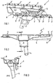
Im Folgenden ist die Erfindung anhand eines besonders bevorzugten Ausführungsbeispieles in drei Figuren näher erläutert.In the following the invention with reference to a particularly preferred embodiment in three figures is explained in more detail.

1 zeigt eine Aufsicht auf ein dreidimensional dargestelltes, Schmiermittelführungsgehäuse. 1 shows a plan view of a three-dimensionally illustrated, lubricant guide housing.

2 zeigt eine Seitenansicht auf das erfindungsgemäße Schmiermittelführungsgehäuse. 2 shows a side view of the lubricant guide housing according to the invention.

3 zeigt einen Schnitt A-A durch das Schmiermittelführungsgehäuse. 3 shows a section AA through the lubricant guide housing.

1 zeigt eine Aufsicht auf ein dreidimensional dargestelltes, Schmiermittelführungsgehäuse 1 für eine erfindungsgemäße Brennkraftmaschine. Das Schmiermittelführungsgehäuse 1 für die Brennkraftmaschine vereint drei Funktionen in einem einzigen Bauteil:

  • 1. Schmiermittelsammler zum Sammeln und zur Rückführung des vom Zylinderkopf in den Schmiermittelsumpf zurücklaufenden Schmiermittels.
  • 2. Schmiermittelsaugrohr zum Ansaugen und Fördern des Schmiermittels durch eine Schmiermittelpumpe zur Schmierung der Brennkraftmaschine.
  • 3. Schmiermittelhobel zur Verringerung einer Schmiermittelverschäumung.
1 shows a plan view of a three-dimensionally illustrated, lubricant guide housing 1 for an internal combustion engine according to the invention. The lubricant guide housing 1 for the internal combustion engine combines three functions in a single component:
  • 1. A lubricant collector for collecting and returning the returning from the cylinder head in the lubricant sump lubricant.
  • 2. Schmiermittelsaugrohr for sucking and conveying the lubricant by a lubricant pump for lubrication of the internal combustion engine.
  • 3. Lubricant planer to reduce lubricant foaming.

Das Schmiermittelführungsgehäuse 1 besteht im Wesentlichen aus einem flachen Boden, der beidseitig in Längsrichtung der Brennkraftmaschine Montageflansche 6, 6' mit Montagebohrungen 7, 7' aufweist. Mit diesen Montagebohrungen 7, 7' kann das Schmiermittelführungsgehäuse 1 entweder geodätisch unten an ein nicht dargestelltes Kurbelgehäuse der Brennkraftmaschine oder geodätisch oben auf eine nicht dargestellte Schmiermittelsammelwanne (Ölwanne) montiert werden, die ihrerseits wiederum an das Kurbelgehäuse montierbar ist. Während der Montageflansch 6 rein zur Montage vorgesehen ist, weist der Montageflansch 6' fünf in das Schmiermittelführungsgehäuse 1 integrierte Kanäle 2, 2' auf, die zu Schmiermittelrücklaufkanälen in dem Kurbelgehäuse korrespondieren. Diese Kanäle 2, 2' werden in dem Schmiermittelführungsgehäuse 1 zusammengeführt und münden in einen einzigen Schmiermittelrücklaufkanal 3. Erfindungsgemäß erstreckt sich dieser Schmiermittelrücklaufkanal 3 bis unter ein Schmiermittelpegel in der nicht dargestellten Schmiermittelsammelwanne. Benachbart zu dem Schmiermittelrücklaufkanal 3 ist ein Schmiermittelsaugrohr 4 in das Schmiermittelführungsgehäuse 1 integriert, welches sich im Schmiermittelführungsgehäuse 1 zuerst geodätisch nach oben und dann zu einer Stirnseite des Schmiermittelführungsgehäuses 1 erstreckt. Stirnseitig weist das Schmiermittelsaugrohr 4 einen Flansch 5 auf, zur Montage einer nicht dargestellten Schmiermittelpumpe. Diese Ausgestaltung erlaubt ein äußerst günstiges Package, bzw. eine äußerst kompakte bauliche Einheit.The lubricant guide housing 1 consists essentially of a flat bottom, the mounting flange on both sides in the longitudinal direction of the engine 6 . 6 ' with mounting holes 7 . 7 ' having. With these mounting holes 7 . 7 ' can the lubricant guide housing 1 either geodetically down to an unillustrated crankcase of the engine or geodetically mounted on top of a non-illustrated lubricant collection tray (oil pan), which in turn is in turn mounted to the crankcase. During the mounting flange 6 is intended purely for mounting, has the mounting flange 6 ' five in the lubricant guide housing 1 integrated channels 2 . 2 ' which correspond to lubricant return passages in the crankcase. These channels 2 . 2 ' be in the lubricant guide housing 1 merged and open into a single lubricant return channel 3 , According to the invention, this lubricant return passage extends 3 to below a lubricant level in the lubricant collection tray, not shown. Adjacent to the lubricant return passage 3 is a lubricant suction tube 4 in the lubricant guide housing 1 integrated, which is located in the lubricant guide housing 1 first geodetically upwards and then to an end face of the lubricant guide housing 1 extends. Front side, the lubricant suction pipe 4 a flange 5 on, for mounting a lubricant pump, not shown. This embodiment allows an extremely favorable package, or an extremely compact structural unit.

Bevorzugt ist das Schmiermittelführungsgehäuse 1 einstückig hergestellt. Auch eine mehrstückige Herstellung mit späterem Fügen zu einem einstückigen Bauteil ist möglich. Hierbei können spezifische Materialeigenschaften für unterschiedliche Funktionen des Schmiermittelführungsgehäuses 1 besonders vorteilhaft kombiniert werden. Besonders bevorzugt wird das Schmiermittelführungsgehäuse 1 aus einem Kunststoff, wie beispielsweise einem Polyamid (PA) oder einem glasfaserverstärktem Kunststoff (GFK) oder einem Leichtmetall, wie beispielsweise Aluminium oder Magnesium hergestellt. Weiter wird das Schmiermittelführungsgehäuse 1 besonders bevorzugt als kostengünstiges Spritzgussteil hergestellt.Preferably, the lubricant guide housing 1 made in one piece. Also a multi-piece production with subsequent joining to a one-piece component is possible. Here, specific material properties for different functions of the lubricant guide housing 1 be combined particularly advantageous. Particularly preferred is the lubricant guide housing 1 made of a plastic, such as a polyamide (PA) or a glass fiber reinforced plastic (GRP) or a light metal, such as aluminum or magnesium. Next, the lubricant guide housing 1 particularly preferably produced as a cost-effective injection molded part.

In 2, in der für gleiche Bauelemente die gleichen Bezugsziffern wie in 1 gelten, ist das Schmiermittelführungsgehäuse 1 in einer Seitenansicht dargestellt.In 2 in which the same reference numbers as in 1 apply, is the lubricant guide housing 1 shown in a side view.

In 2 ist in Blickrichtung vorne liegend der Montageflansch 6' erkennbar, wobei der Schmiermittelrücklaufkanal 3 in Blickrichtung vor dem Schmiermittelsaugrohr 4 ist. In 2 ist auch gut ersichtlich, wie sich das tief in die Schmiermittelsammelwanne reichende Schmiermittelsaugrohr 4 erst geodätisch nach oben und weiter in Richtung der Stirnseite des Schmiermittelführungsgehäuses 1 erstreckt und an der Stirnseite als Flansch 5 für die nicht dargestellte Schmiermittelpumpe endet.In 2 is in the direction of the front lying the mounting flange 6 ' recognizable, wherein the lubricant return passage 3 in the direction of view in front of the lubricant suction tube 4 is. In 2 It is also easy to see how the lubricant suction pipe reaching deep into the lubricant collection tray is 4 first geodetically upward and further towards the front side of the lubricant guide housing 1 extends and at the front as a flange 5 for the lubricant pump, not shown ends.

In 3, in der ebenfalls für gleiche Bauelemente die gleichen Bezugsziffern wie in den 1 und 2 gelten, ist ein Schnitt A-A aus 2 durch das Schmiermittelführungsgehäuse 1 dargestellt. Der Schnitt A-A in 3 erstreckt sich durch den einzigen Schmiermittelrücklaufkanal 3 und zeigt nochmals eine Aufsicht auf das Schmiermittelsaugrohr 4. Ein Pfeil symbolisiert eine Abfließrichtung des Schmiermittels, von den Kanälen 2, 2' kommend in den Schmiermittelrücklaufkanal 3.In 3 in which also for the same components the same reference numerals as in 1 and 2 apply, a cut AA is off 2 through the lubricant guide housing 1 shown. The cut AA in 3 extends through the single lubricant return passage 3 and again shows a plan view of the lubricant suction 4 , An arrow symbolizes a discharge direction of the lubricant, of the channels 2 . 2 ' coming into the lubricant return channel 3 ,

Durch die Ausgestaltung des Schmiermittelführungsgehäuses 1 für eine erfindungsgemäße Brennkraftmaschine werden in vorteilhafter Weise die drei Funktionen Schmiermittelsammler, Schmiermittelsaugrohr und Schmiermittelhobel in einem einzigen Bauteil realisiert. Weiter wird durch die erfindungsgemäße Ausgestaltung in bestimmten Betriebssituationen der Brennkraftmaschine, wie z. B. extremen Schwenklagen, oder Beschleunigungszuständen und Kurvenfahrten, eine Schmiermittelverschäumung verringert.Due to the design of the lubricant guide housing 1 For an internal combustion engine according to the invention, the three functions of lubricant collector, lubricant suction pipe and lubricant planer are realized in a single component in an advantageous manner. Next, the inventive design in certain operating situations of the internal combustion engine, such as. B. extreme slewing, or acceleration states and cornering, a lubricant foaming reduced.

BezugszeichenlisteLIST OF REFERENCE NUMBERS

11
SchmiermittelführungsgehäuseLubricant guide housing
2, 2'2, 2 '
Kanalchannel
33
SchmiermittelrücklaufkanalLubricant return channel
44
SchmiermittelsaugrohrSchmiermittelsaugrohr
55
Flanschflange
6, 6'6, 6 '
MonatageflanschMonatageflansch
7, 7'7, 7 '
Montagebohrungmounting hole

Claims (6)

Brennkraftmaschine mit einem Kurbelgehäuse und einer geodätisch unter dem Kurbelgehäuse angeordneten Schmiermittelsammelwanne, wobei ein Schmiermittelführungsgehäuse (1) zwischen dem Kurbelgehäuse und der Schmiermittelsammelwanne angeordnet ist und wobei das Kurbelgehäuse zumindest zwei Schmiermittelrücklaufkanäle aufweist, dadurch gekennzeichnet, dass die Schmiermittelrücklaufkanäle zur Rückführung des von einem Zylinderkopf in einen Schmiermittelsumpf zurücklaufenden Schmiermittels vorgesehen sind und das Schmiermittelführungsgehäuse zu den Schmiermittelrücklaufkanälen korrespondierende Kanäle (2, 2') aufweist, die in einen einzigen Schmiermittelrücklaufkanal (3) münden, der sich bis unter einen Schmiermittelpegel in der Schmiermittelsammelwanne erstreckt und wobei das Schmiermittelführungsgehäuse ein Schmiermittelsaugrohr (4) für eine Schmiermittelpumpe aufweist.Internal combustion engine with a crankcase and a geodetically arranged under the crankcase lubricant collection tray, wherein a lubricant guide housing ( 1 ) is arranged between the crankcase and the lubricant collecting trough and wherein the crankcase has at least two lubricant return passages, characterized in that the lubricant return passages are provided for returning the lubricant returning from a cylinder head into a lubricant sump and the lubricant guide housing is provided with channels corresponding to the lubricant return passages ( 2 . 2 ' ) in a single lubricant return channel ( 3 ) which extends to below a lubricant level in the lubricant collection trough and wherein the lubricant guide housing a lubricant suction ( 4 ) for a lubricant pump. Brennkraftmaschine nach Patentanspruch 1, dadurch gekennzeichnet, dass das Schmiermittelführungsgehäuse (1) einstückig ist.Internal combustion engine according to claim 1, characterized in that the lubricant guide housing ( 1 ) is integral. Brennkraftmaschine nach Patentanspruch 1 oder 2, dadurch gekennzeichnet, dass das Schmiermittelführungsgehäuse (1) an das Kurbelgehäuse oder an die Schmiermittelsammelwanne montiert ist.Internal combustion engine according to claim 1 or 2, characterized in that the lubricant guide housing ( 1 ) is mounted on the crankcase or on the lubricant collection tray. Brennkraftmaschine nach einem der Patentansprüche 1 bis 3, dadurch gekennzeichnet, dass das Schmiermittelsaugrohr (4) einen Flansch (5) für eine Schmiermittelpumpe aufweist.Internal combustion engine according to one of the claims 1 to 3, characterized in that the lubricant suction pipe ( 4 ) a flange ( 5 ) for a lubricant pump. Brennkraftmaschine nach einem der Patentansprüche 1 bis 4, dadurch gekennzeichnet, dass das Schmiermittelführungsgehäuse (1) aus einem Kunststoff oder einem Leichtmetall ist.Internal combustion engine according to one of the claims 1 to 4, characterized in that the lubricant guide housing ( 1 ) is made of a plastic or a light metal. Brennkraftmaschine nach Patentanspruch 5, dadurch gekennzeichnet, dass das Schmiermittelführungsgehäuse (1) ein Spritzgussteil ist.Internal combustion engine according to claim 5, characterized in that the lubricant guide housing ( 1 ) is an injection molded part.
DE102008009873.6A 2008-02-19 2008-02-19 Internal combustion engine Active DE102008009873B4 (en)

Priority Applications (1)

Application Number Priority Date Filing Date Title
DE102008009873.6A DE102008009873B4 (en) 2008-02-19 2008-02-19 Internal combustion engine

Applications Claiming Priority (1)

Application Number Priority Date Filing Date Title
DE102008009873.6A DE102008009873B4 (en) 2008-02-19 2008-02-19 Internal combustion engine

Publications (2)

Publication Number Publication Date
DE102008009873A1 DE102008009873A1 (en) 2009-09-03
DE102008009873B4 true DE102008009873B4 (en) 2017-11-02

Family

ID=40911167

Family Applications (1)

Application Number Title Priority Date Filing Date
DE102008009873.6A Active DE102008009873B4 (en) 2008-02-19 2008-02-19 Internal combustion engine

Country Status (1)

Country Link
DE (1) DE102008009873B4 (en)

Cited By (1)

* Cited by examiner, † Cited by third party
Publication number Priority date Publication date Assignee Title
DE102020100538A1 (en) 2020-01-13 2021-07-15 Bayerische Motoren Werke Aktiengesellschaft Internal combustion engine

Families Citing this family (3)

* Cited by examiner, † Cited by third party
Publication number Priority date Publication date Assignee Title
DE102008060411B4 (en) * 2008-11-28 2023-03-23 Dr. Ing. H.C. F. Porsche Aktiengesellschaft combustion engine
FR2964146B1 (en) * 2010-08-27 2014-08-29 Peugeot Citroen Automobiles Sa ANTI-EMULSION PLATE ENABLING THE OPTIMIZATION OF LUBRICATION OF MECHANICAL BONDS
DE102014225360B4 (en) 2014-12-10 2017-11-02 Bayerische Motoren Werke Aktiengesellschaft Lubricant guide housing with bulkhead function and return

Citations (6)

* Cited by examiner, † Cited by third party
Publication number Priority date Publication date Assignee Title
EP0437681B1 (en) * 1990-01-19 1993-12-08 Dr.Ing.h.c. F. Porsche Aktiengesellschaft Internal combustion engine oil pan
DE19619977C2 (en) * 1996-05-17 1998-07-02 Daimler Benz Ag Oil pan for an internal combustion engine
DE4139195C2 (en) * 1991-11-28 1999-05-27 Audi Ag Oil pan insert
DE19958743A1 (en) * 1999-10-06 2001-04-19 Daimler Chrysler Ag Oil deflector for oil sump of internal combustion engine has two overlapping deflector plates with longitudinal edge of second plate forming a main stripper edge and with guide strips in overlapping area to direct oil
DE10026113A1 (en) * 2000-05-26 2001-11-29 Opel Adam Ag Internal combustion engine with crankcase oil deflectors uses oil return channels from cylinder crankcase housing to sump and additional channel as part of pump intake.
DE102004024517A1 (en) * 2004-05-18 2005-12-15 Adam Opel Ag An oil sump assembly

Patent Citations (6)

* Cited by examiner, † Cited by third party
Publication number Priority date Publication date Assignee Title
EP0437681B1 (en) * 1990-01-19 1993-12-08 Dr.Ing.h.c. F. Porsche Aktiengesellschaft Internal combustion engine oil pan
DE4139195C2 (en) * 1991-11-28 1999-05-27 Audi Ag Oil pan insert
DE19619977C2 (en) * 1996-05-17 1998-07-02 Daimler Benz Ag Oil pan for an internal combustion engine
DE19958743A1 (en) * 1999-10-06 2001-04-19 Daimler Chrysler Ag Oil deflector for oil sump of internal combustion engine has two overlapping deflector plates with longitudinal edge of second plate forming a main stripper edge and with guide strips in overlapping area to direct oil
DE10026113A1 (en) * 2000-05-26 2001-11-29 Opel Adam Ag Internal combustion engine with crankcase oil deflectors uses oil return channels from cylinder crankcase housing to sump and additional channel as part of pump intake.
DE102004024517A1 (en) * 2004-05-18 2005-12-15 Adam Opel Ag An oil sump assembly

Cited By (1)

* Cited by examiner, † Cited by third party
Publication number Priority date Publication date Assignee Title
DE102020100538A1 (en) 2020-01-13 2021-07-15 Bayerische Motoren Werke Aktiengesellschaft Internal combustion engine

Also Published As

Publication number Publication date
DE102008009873A1 (en) 2009-09-03

Similar Documents

Publication Publication Date Title
EP1751405B1 (en) Oil pan arrangement
EP0437681B1 (en) Internal combustion engine oil pan
EP1360400B1 (en) Oil collecting device for an internal combustion engine
DE102005025218B4 (en) Cooling structure of a motor
EP1761689A1 (en) Internal combustion engine with lubrication by circulation of oil under pressure according to the dry sump principle
WO2006000268A1 (en) Internal combustion engine with lubrication by circulation of oil under pressure according to the dry sump principle
DE102008009873B4 (en) Internal combustion engine
DE3842887A1 (en) LUBRICATION SYSTEM FOR ENGINES
DE4424248C1 (en) Internal combustion engine with two cylinder banks inclined against the vertical
DE10026113A1 (en) Internal combustion engine with crankcase oil deflectors uses oil return channels from cylinder crankcase housing to sump and additional channel as part of pump intake.
DE4139195A1 (en) Oil sump inserts in IC engine crankcase - use air pulses in chamber to direct oil flow in sump over crank to pump
DE10159104B4 (en) Internal combustion engine
DE10016071B4 (en) Lubricating arrangement for a four-stroke engine
DE10014368A1 (en) Oil collecting device and oil pump for an internal combustion engine
DE60019025T2 (en) Four-stroke internal combustion engine
DE102008060409B4 (en) combustion engine
DE102019114407A1 (en) Internal combustion engine for a saddle seat vehicle
DE19509002C2 (en) Thermostat mounting structure
DE102016200074B4 (en) Internal combustion engine
DE112015000036B4 (en) Mounting structure for a fuel pump
EP2525055A2 (en) Combustion engine
DE102020200696A1 (en) COMBUSTION ENGINE WITH COVERING STRUCTURE
DE102011103180A1 (en) Two-stroke engine
DE202004004802U1 (en) Oil return apparatus for recirculating oil disposed of in blow by gases during operation of a combustion engine
DE102019112322A1 (en) Oil pan assembly for an internal combustion engine

Legal Events

Date Code Title Description
OM8 Search report available as to paragraph 43 lit. 1 sentence 1 patent law
OP8 Request for examination as to paragraph 44 patent law
R016 Response to examination communication
R018 Grant decision by examination section/examining division
R020 Patent grant now final