DE102006051857B4 - check valve - Google Patents
check valve Download PDFInfo
- Publication number
- DE102006051857B4 DE102006051857B4 DE200610051857 DE102006051857A DE102006051857B4 DE 102006051857 B4 DE102006051857 B4 DE 102006051857B4 DE 200610051857 DE200610051857 DE 200610051857 DE 102006051857 A DE102006051857 A DE 102006051857A DE 102006051857 B4 DE102006051857 B4 DE 102006051857B4
- Authority
- DE
- Germany
- Prior art keywords
- closing element
- valve
- check valve
- cross
- flow channel
- Prior art date
- Legal status (The legal status is an assumption and is not a legal conclusion. Google has not performed a legal analysis and makes no representation as to the accuracy of the status listed.)
- Expired - Fee Related
Links
Images

Classifications
-
- F—MECHANICAL ENGINEERING; LIGHTING; HEATING; WEAPONS; BLASTING
- F16—ENGINEERING ELEMENTS AND UNITS; GENERAL MEASURES FOR PRODUCING AND MAINTAINING EFFECTIVE FUNCTIONING OF MACHINES OR INSTALLATIONS; THERMAL INSULATION IN GENERAL
- F16K—VALVES; TAPS; COCKS; ACTUATING-FLOATS; DEVICES FOR VENTING OR AERATING
- F16K15/00—Check valves
- F16K15/02—Check valves with guided rigid valve members
- F16K15/025—Check valves with guided rigid valve members the valve being loaded by a spring
- F16K15/026—Check valves with guided rigid valve members the valve being loaded by a spring the valve member being a movable body around which the medium flows when the valve is open
Abstract
Rückschlagventil, 1.1 mit einem Ventilgehäuse (1), das einen Strömungskanal von einem Ventileinlass (2) zu einem Ventilauslass (3) begrenzt; wobei 1.2 das Ventilgehäuse (1) wenigstens einen Ventilanschlag (4) ausbildet, der mit einem im oder am Venti (5) zusammenwirkt, um den Querschnitt des Strömungskanals durch Bewegen des Schließelementes (5) zu variieren; 1.3 mit einem elastischen Federelement (6), durch welches das Schließelement (5) in eine erste Richtung kraftbeaufschlagt ist; 1.4 die Kraft des Federelementes (6) in die erste Richtung wirkt auf das Schließelement (5) im Sinne eines Abhebens desselben vom Ventilanschlag (4) und entgegen einer Strömungskraft, welche von einer Mediumströmung vom Ventileinlass (2) zum Ventilauslass (3) in einer zweiten Richtung auf das Schließelement (5) aufgebracht wird; 1.5 das Schließelement (5) begrenzt zusammen mit den Ventilanschlag (4) einen ersten Querschnittsbereich (7) des Strömungskanals, es (5) aufgrund des sich einstellenden...Check valve, 1.1 with a valve housing (1) which delimits a flow channel from a valve inlet (2) to a valve outlet (3); 1.2 the valve housing (1) forming at least one valve stop (4) which interacts with one in or on the valve (5) in order to vary the cross section of the flow channel by moving the closing element (5); 1.3 with an elastic spring element (6) through which the closing element (5) is acted upon by force in a first direction; 1.4 the force of the spring element (6) in the first direction acts on the closing element (5) in the sense of lifting it off the valve stop (4) and against a flow force which is generated by a medium flow from the valve inlet (2) to the valve outlet (3) in one the second direction is applied to the closing element (5); 1.5 the closing element (5), together with the valve stop (4), limits a first cross-sectional area (7) of the flow channel, it (5) due to the ...
Description
Die Erfindung betrifft ein Rückschlagventil, beispielsweise zur Verwendung in einem Fahrzeug, in der Regel Kraftfahrzeug, hier insbesondere in dessen Ölkreislauf oder Kühlwasserkreislauf.The invention relates to a check valve, for example, for use in a vehicle, usually motor vehicle, here in particular in the oil circuit or cooling water circuit.
Rückschlagventile sind in verschiedenen Ausführungsformen bekannt und werden beispielsweise als Überdruckventil verwendet. Die bekannten Rückschlagventile weisen ein Schließelement, auch Ventilkörper oder Strömungskörper genannt, auf, das mit einem Ventilsitz derart zusammenwirkt, dass der Strömungskanal für ein Medium durch das Rückschlagventil in einem ersten Schaltzustand abgesperrt ist, weil das Schließelement abdichtend auf dem Ventilsitz sitzt, und in einem zweiten Schaltzustand geöffnet ist, in welchem das Schließelement vom Ventilsitz abgehoben ist. In der Regel ist eine Druckfeder in dem Rückschlagventil vorgesehen, welche auf das Schließelement in Richtung des Ventilsitzes und somit im Sinne eines Schließens drückt. Wenn die Strömungskräfte der Mediumströmung durch das Rückschlagventil, welche das Schließelement beaufschlagen und entgegen der Kraft der Druckfeder wirken, die Federkraft übersteigen, wird das Rückschlagventil geöffnet, wohingegen es geschlossen bleibt, solange die Strömungskräfte kleiner als die Kraft der Druckfeder sind.Check valves are known in various embodiments and are used for example as a pressure relief valve. The known check valves have a closing element, also called valve body or flow body, which cooperates with a valve seat such that the flow channel for a medium is shut off by the check valve in a first switching state, because the closing element is sealingly seated on the valve seat, and in a second switching state is opened, in which the closing element is lifted from the valve seat. In general, a compression spring is provided in the check valve, which presses on the closing element in the direction of the valve seat and thus in the sense of closing. If the flow forces of the medium flow through the check valve, which act on the closing element and act against the force of the compression spring, the spring force, the check valve is opened, whereas it remains closed as long as the flow forces are smaller than the force of the compression spring.
Ein besonderer Anwendungsfall für das Rückschlagventil der vorliegenden Erfindung ist die Verwendung desselben in einem Mediumkreislauf, in welchem der Druck, insbesondere statische Druck des Mediums, vor dem Rückschlagventil stark variiert. Dies ist beispielsweise im Motorölkreislauf eines Kraftfahrzeugs oder einer anderen Vorrichtung der Fall, bei welchem das Öl mittels einer Ölpumpe in einem Kreislauf umgewälzt wird. Die Förderleistung der Ölpumpe und damit der Förderdruck, auf welchen die Ölpumpe das Öl fördert, variiert mit der Drehzahl der Ölpumpe. Wenn die Ölpumpe beispielsweise von einer Antriebsmaschine eines Kraftfahrzeugs, insbesondere einer Brennkraftmaschine, angetrieben wird, so variiert die Drehzahl der Ölpumpe in Abhängigkeit der Drehzahl der Antriebsmaschine. Um alle Aggregate, die mit dem Öl des Ölkreislaufes, insbesondere Motorölkreislaufes, versorgt werden, in jedem Betriebszustand mit einer ausreichenden Ölmenge je Zeiteinheit zu versorgen, muss der Strömungsquerschnitt zu dem jeweiligen Aggregat derart groß ausgeführt werden, dass auch bei einem niedrigen Öldruck eine ausreichende Ölmenge (je Zeiteinheit) dem Aggregat zugeführt wird. Wenn nun bei einer höheren Antriebsdrehzahl beziehungsweise Ölpumpendrehzahl der Öldruck ansteigt, führt dieser große Querschnitt dazu, dass dem einzelnen Aggregat übermäßig viel Öl zugeführt wird. Dieses überschüssig zugeführte Öl bringt in dem Aggregat keinen Vorteil und steht anderen Aggregaten nicht zur Verfügung.A particular application for the check valve of the present invention is the use of the same in a medium circuit in which the pressure, in particular static pressure of the medium, varies greatly in front of the check valve. This is the case for example in the engine oil circuit of a motor vehicle or another device, in which the oil is circulated by means of an oil pump in a circuit. The delivery rate of the oil pump and thus the delivery pressure at which the oil pump delivers the oil varies with the speed of the oil pump. When the oil pump is driven, for example, by an engine of a motor vehicle, in particular an internal combustion engine, the rotational speed of the oil pump varies as a function of the rotational speed of the engine. In order to supply all units that are supplied with the oil of the oil circuit, in particular engine oil circuit, in each operating state with a sufficient amount of oil per unit time, the flow cross-section must be made to the respective unit so large that even at a low oil pressure sufficient oil (per unit time) is supplied to the unit. Now, if the oil pressure increases at a higher input speed or oil pump speed, this large cross-section causes the individual unit is supplied excessively oil. This excess supply oil brings no advantage in the unit and is not available to other units.
In dem beschriebenen Anwendungsfall, der nicht auf das Strömungsmedium Öl beschränkt ist, da beispielsweise auch ein entsprechender Wasserkreislauf, beispielsweise Kühlwasserkreislauf, insbesondere eines Fahrzeugs demselben Problem unterworfen ist, können herkömmlich ausgeführte Rückschlagventile den unerwünscht hohen „Ölverbrauch” beziehungsweise Wasserverbrauch einzelner Aggregate in einem Zustand hohen Öldruckes beziehungsweise Wasserdruckes nicht vermeiden.In the application described, which is not limited to the flow medium oil, as for example, a corresponding water cycle, for example, cooling water circuit, especially a vehicle subject to the same problem, conventionally designed check valves the high undesirable "oil consumption" or water consumption of individual units in a state Oil pressure or water pressure can not be avoided.
Der Erfindung liegt die Aufgabe zugrunde, ein insbesondere auf den zuvor beschriebenen Anwendungsfall angepasstes Rückschlagventil darzustellen, welches zum einen eine ausreichende Mediumströmung durch den Strömungskanal des Rückschlagventils bei niedrigen Drücken in dem Strömungsmedium vor dem Rückschlagventil sicherstellt und zugleich eine unerwünscht hohe Strömungsmenge des Mediums durch den Strömungskanal bei hohen Druckzuständen im Medium vor dem Rückschlagventil vermeidet. Vorteilhaft soll das erfindungsgemäße Rückschlagventil die gleichen Vorteile wie herkömmliche Rückschlagventile aufweisen, nämlich kostengünstig herstellbar sein, mediumbetätigt statt fremdbetätigt und wartungsarm beziehungsweise wartungsfrei sein, sowie zuverlässig arbeiten.The invention has for its object to present a particular adapted to the application described above non-return valve, which ensures a sufficient medium flow through the flow channel of the check valve at low pressures in the flow medium in front of the check valve and at the same time an undesirably high flow rate of the medium through the flow channel avoids at high pressure conditions in the medium before the check valve. Advantageously, the check valve according to the invention should have the same advantages as conventional check valves, namely be inexpensive to produce, medium-actuated instead of externally operated and low-maintenance or maintenance-free, and work reliably.
Die erfindungsgemäße Aufgabe wird durch ein Rückschlagventil mit den Merkmalen von Anspruch 1 gelöst. In den abhängigen Ansprüchen sind vorteilhafte und besonders zweckmäßige Ausgestaltungen der Erfindung angegeben.The object of the invention is achieved by a check valve having the features of
Das erfindungsgemäße Rückschlagventil ermöglicht gemäß einer Ausführungsform eine permanente Strömung von Medium durch den Strömungskanal, wobei der letztere bei einem Druckanstieg in dem Strömungsmedium vor dem Rückschlagventil beziehungsweise im Ventileinlass mediumsbetätigt und frei von einer externen Betätigung (Fremdbetätigung) und somit selbsttätig in seinem Querschnitt reduziert wird.According to one embodiment, the non-return valve according to the invention allows a permanent flow of medium through the flow channel, the latter being medium-actuated at a pressure increase in the flow medium upstream of the check valve or in the valve inlet and free of external actuation (external actuation) and thus automatically reduced in its cross-section.
Ferner ist das erfindungemäße Rückschlagventil äußerst kostengünstig, besonders in großen Stückzahlen herstellbar, insbesondere bei Verwendung eines Baukastensystems, welches weiter unten noch beschrieben wird, mittels welchem Rückschlagventile mit verschiedenen Strömungskanälen besonders einfach in demselben Werkzeug beziehungsweise mit denselben Maschinen hergestellt werden können.Furthermore, the inventive check valve is extremely inexpensive, especially in large quantities produced, especially when using a modular system, which will be described below, by means of which non-return valves with different flow channels can be particularly easily manufactured in the same tool or with the same machines.
Das erfindungsgemäße Rückschlagventil weist im einzelnen ein Ventilgehäuse auf, das einen Strömungskanal begrenzt, der von einem Ventileinlass in dem Ventilgehäuse, insbesondere an einem ersten axialen Ende desselben, zu einem Ventilauslass in dem Ventilgehäuse, insbesondere an einem zweiten, entgegengesetzt zu dem ersten axialen Ende angeordneten zweiten axialen Ende, reicht. Das Ventilgehäuse bildet wenigstens einen Ventilanschlag aus, kann jedoch auch mehrere Ventilanschläge, die mit einem oder mehreren Ventilkörpern, Drosselelementen und/oder Schließelementen zusammenwirken, umfassen.The check valve according to the invention has in detail a valve housing which defines a flow channel, the one of Valve inlet in the valve housing, in particular at a first axial end thereof, to a valve outlet in the valve housing, in particular at a second, opposite to the first axial end disposed second axial end, extends. The valve housing forms at least one valve stop, but may also comprise a plurality of valve stops, which interact with one or more valve bodies, throttle elements and / or closing elements.
Das Ventilgehäuse umfasst eine Hülse und einen darin eingesetzten Einsatz. Der Einsatz ist aus Kunststoff hergestellt. Die Hülse ist aus Metall oder als Blechteil ausgeführt.The valve housing comprises a sleeve and an insert inserted therein. The insert is made of plastic. The sleeve is made of metal or as a sheet metal part.
Das Rückschlagventil weist wenigstens ein Schließelement aus Kunststoff auf, welches mit dem genannten Ventilanschlag zusammenwirkt, um den Querschnitt des Strömungskanals durch Bewegen, insbesondere Verschieben, beispielsweise geradliniges Verschieben, des Schließelements zu variieren. Wenn das Schließelement in Richtung des Ventilanschlages bewegt wird, wird der Querschnitt des Strömungskanals reduziert, und wenn das Schießelement von dem Ventilanschlag wegbewegt wird, wird der Querschnitt des Strömungskanals vergrößert.The check valve has at least one closing element made of plastic, which cooperates with said valve stop to vary the cross-section of the flow channel by moving, in particular shifting, for example rectilinear shifting, of the closing element. When the closing element is moved in the direction of the valve stop, the cross section of the flow channel is reduced, and when the shooting element is moved away from the valve stop, the cross section of the flow channel is increased.
Das Schließelement ist durch ein elastisches Federelement, beispielsweise eine Druckfeder, Zugfeder, Torsionsfeder oder auch eine elastische Membran oder Bänder oder dergleichen, kraftbeaufschlagt, und zwar im Sinne eines Abhebens beziehungsweise Wegbewegens des Schließelementes von dem Ventilanschlag.The closing element is powered by an elastic spring element, such as a compression spring, tension spring, torsion spring or an elastic membrane or bands or the like, in the sense of lifting or moving away the closing element of the valve stop.
Der Druck des im Ventileinlass anstehenden Mediums beziehungsweise der Druckdifferenzdruck des Mediums über dem Schließelement wirkt entgegen der Kraft des Federelementes im Sinne eines Reduzierens beziehungsweise Schließens des Querschnittbereiches des Strömungskanals zwischen dem Schließelement und dem Ventilanschlag. Bei einem hohen Druck im Medium kann somit die Kraft des Federelementes durch das Medium überwunden und das Schließelement auf den Ventilanschlag vollflächig oder abschnittsweise aufgesetzt werden. Der Ventilanschlag bestimmt somit die Endlage des Schließelementes.The pressure of the pending in the valve inlet medium or the pressure differential pressure of the medium over the closing element acts against the force of the spring element in the sense of reducing or closing the cross-sectional area of the flow channel between the closing element and the valve stop. At a high pressure in the medium thus the force of the spring element can be overcome by the medium and the closing element on the valve stop over the entire surface or sections are placed. The valve stop thus determines the end position of the closing element.
Erfindungsgemäß begrenzt jedoch das Schließelement zusammen mit dem Ventilanschlag nur einen ersten Querschnittsbereich des Strömungskanals, wobei die Größe dieses ersten Querschnittsbereiches, wie beschrieben, durch die Bewegung des Schließelementes aufgrund des sich einstellenden Kräfteverhältnisses zwischen der Kraft des Federelementes und der Strömungskraft variiert und insbesondere in bestimmten Betriebszuständen mit einer hohen Strömungskraft beziehungsweise einem hohen, insbesondere statischen Druck in der Strömung in Strömungsrichtung vor dem Schließelement vollständig oder im wesentlichen abgesperrt wird. Unter Kräfteverhältnis ist im Sinne der vorliegenden Beschreibung nicht nur der Quotient zwischen den, insbesondere auf entgegengesetzten Seiten des Schließelementes angreifenden Kräften der Strömung und des Federelementes zu verstehen, sondern auch die Differenz zwischen den entsprechenden Kräften soll von diesem Begriff umfasst sein.According to the invention, however, the closing element together with the valve stop limits only a first cross-sectional area of the flow channel, wherein the size of this first cross-sectional area, as described, by the movement of the closing element due to the self-adjusting force ratio between the force of the spring element and the flow force varies and in particular in certain operating conditions is completely or substantially shut off with a high flow force or a high, in particular static pressure in the flow in the flow direction before the closing element. For the purposes of the present description, "force ratio" is to be understood as meaning not only the quotient between the forces acting on opposite sides of the closing element of the flow and the spring element, but also the difference between the corresponding forces should be encompassed by this term.
Dem ersten Querschnittsbereich des Strömungskanals ist bezogen auf die Mediumströmung vom Ventileinlass zum Ventilauslass ein zweiter zusätzlicher Querschnittsbereich parallel geschaltet, dessen für die Strömung des Mediums zur Verfügung stehende Größe unabhängig von der Bewegung und/oder der Position des Schließelementes relativ zu dem Ventilanschlag ist. Unabhängig bedeutet dabei im Sinne der vorliegenden Beschreibung eine vollständige Unabhängigkeit oder eine wesentliche Unabhängigkeit. Je nach Aufbau des Rückschlagventils kann nämlich eine geringe Auswirkung auf den wirksamen Strömungsquerschnitt des zweiten Querschnittsbereiches bei einer Bewegung des Schließelementes nicht ausgeschlossen werden. Der zweite Querschnittsbereich kann ferner auch in Abhängigkeit des Hubs beziehungsweise der axialen Position des Schließelementes variierend ausgeführt sein.With reference to the medium flow from the valve inlet to the valve outlet, the first cross-sectional area of the flow channel is connected in parallel with a second additional cross-sectional area whose size, which is available for the flow of the medium, is independent of the movement and / or the position of the closing element relative to the valve stop. For the purposes of the present description, independent means complete independence or significant independence. Depending on the design of the non-return valve, a slight effect on the effective flow cross-section of the second cross-sectional area can not be ruled out during a movement of the closing element. The second cross-sectional area may also be made varying depending on the stroke or the axial position of the closing element.
Insofern gemäß einer Ausführung der Erfindung keine weiteren Absperrorgane im Rückschlagventil vorgesehen sind, wird somit erreicht, dass einerseits immer eine Mediumströmung vom Ventileinlass zum Ventilauslass möglich ist, jedoch die Strömungsmenge mit zunehmendem Mediumdruck vor dem Rückschlagventil nicht stetig beziehungsweise proportional zunimmt, sondern der für die Mediumströmung zur Verfügung stehende Strömungsquerschnitt oberhalb eines vorgegebenen Druckes im Ventileinlass beziehungsweise einer Druckdifferenz beziehungsweise einem Druckverhältnis zwischen Ventileinlass und Ventilauslass reduziert wird, und somit die vom Ventileinlass zum Ventilauslass strömende Menge gegenüber einem Strömungskanal mit nicht „geschaltet” reduzierten Strömungskanalquerschnitt vermindert wird.Insofar as according to an embodiment of the invention, no further shut-off valves are provided in the check valve, it is thus achieved that on the one hand always a medium flow from the valve inlet to the valve outlet is possible, but the flow rate with increasing medium pressure before the check valve does not increase steadily or proportionally, but the medium flow available flow cross-section above a predetermined pressure in the valve inlet or a pressure difference or a pressure ratio between the valve inlet and valve outlet is reduced, and thus the amount flowing from the valve inlet to the valve outlet is reduced compared to a flow channel with not "switched" reduced flow channel cross-section.
Gemäß einer Ausführungsform wird das Schließelement durch das Federelement gegen einen ersten Anschlag, auch Ventilsitz genannt, im Ventilgehäuse, insbesondere exakt oder im wesentlichen entgegen der Strömungsrichtung des Mediums durch das Rückschlagventil, gedrückt, solange die Strömungskraft auf das Schließelement geringer als die Federkraft des Federelementes auf das Schließelement ist, und wird, wenn die Strömungskraft die Federkraft überschreitet, von dem Ventilsitz abgehoben und gegen den beschriebenen Ventilanschlag, welcher dann einen zweiten Anschlag im Ventilgehäuse ausbildet, gedrückt. Solange das Schließelement auf dem Ventilsitz aufsitzt, ist der erste Querschnittsbereich vorteilhaft vollständig oder im wesentlichen freigegeben, wohingegen er, wenn das Schließelement am Ventilanschlag (dem zweiten Anschlag) aufsitzt, im wesentlichen oder vollständig geschlossen ist.According to one embodiment, the closing element is pressed by the spring element against a first stop, also valve seat, in the valve housing, in particular exactly or substantially against the direction of flow of the medium through the check valve, as long as the flow force to the closing element less than the spring force of the spring element is the closing element, and when the flow force exceeds the spring force, lifted from the valve seat and against the described Valve stop, which then forms a second stop in the valve housing, pressed. As long as the closing element is seated on the valve seat, the first cross-sectional area is advantageously completely or substantially released, whereas when the closing element is seated on the valve stop (the second stop) it is substantially or completely closed.
Gemäß einer besonderen Ausführungsform kann der Querschnittsverlauf des ersten Querschnittsbereiches entlang dem und/oder durch das Schließelement jedoch derart gestaltet werden, dass in Abhängigkeit der Position des Schließelementes drei oder mehr verschieden große Querschnitte für die Mediumströmung durch den ersten Querschnittsbereich freigegeben werden, nämlich ein erster Querschnitt, solange das Schließelement auf dem Ventilsitz aufsitzt, ein zweiter Querschnitt, solange sich das Schließelement zwischen dem Ventilsitz und dem Ventilanschlag befindet und weder auf dem Ventilsitz noch auf dem Ventilanschlag aufsitzt, und einen dritten Querschnitt, wenn das Schließelement auf dem Ventilanschlag aufsitzt. Die dritte Schaltstellung, wenn das Schließelement auf dem Ventilanschlag aufsitzt, wird in der Regel den kleinsten Querschnitt für die Mediumströmung durch den ersten Querschnittsbereich zur Verfügung stellen, wohingegen entweder die genannte erste Schaltstellung, wenn das Schließelement am Ventilsitz aufsitzt, oder die zweite Schaltstellung, in welcher das Schließelement nicht berührend zwischen dem Ventilsitz und dem Ventilanschlag positioniert ist, je nach gewünschter Verhaltensweise, den größten Querschnitt für die Mediumströmung durch den ersten Querschnittsbereich zur Verfügung stellen können.According to a particular embodiment, however, the cross-sectional profile of the first cross-sectional area along and / or through the closing element can be designed such that depending on the position of the closing element, three or more differently sized cross sections for the medium flow through the first cross-sectional area are released, namely a first cross section as long as the closing element is seated on the valve seat, a second cross-section, as long as the closing element between the valve seat and the valve stop and is seated neither on the valve seat nor on the valve stop, and a third cross-section, when the closing element is seated on the valve stop. The third switching position, when the closing element is seated on the valve stop, will generally provide the smallest cross-section for the medium flow through the first cross-sectional area, whereas either said first switching position, when the closing element is seated on the valve seat, or the second switching position, in which the closing element is not positioned between the valve seat and the valve stop, depending on the desired behavior, can provide the largest cross-section for the medium flow through the first cross-sectional area.
Der zweite Querschnitt (des ersten Querschnittsbereiches) kann beispielsweise in Abhängigkeit des Abstandes des Schließelementes vom Ventilsitz beziehungsweise vom Ventilanschlag variierend ausgeführt sein. Dies kann beispielsweise durch eine konische Bohrung, innerhalb von welcher das Schließelement gleitet, erreicht werden.The second cross section (of the first cross-sectional area) may be designed to vary, for example, depending on the distance of the closing element from the valve seat or from the valve stop. This can be achieved, for example, by a conical bore, within which the closing element slides.
Besonders vorteilhaft wird der zweite Querschnittsbereich durch eine Axialbohrung durch das Schließelement hindurch ausgebildet. Der zweite Querschnittsbereich weist vorteilhaft stets dieselbe Strömungsfläche auf. Es ist jedoch möglich, auch die Querschnittsfläche des zweiten Querschnittsbereiches zu reduzieren, beispielsweise durch ein weiteres Schließelement oder einen Drosselkörper. Hier kann beispielsweise auf bekannte Kombinationen aus Schließelement beziehungsweise Drosselkörper und Ventilanschlag zurückgegriffen werden.Particularly advantageously, the second cross-sectional area is formed through an axial bore through the closing element. The second cross-sectional area advantageously always has the same flow area. However, it is also possible to reduce the cross-sectional area of the second cross-sectional area, for example by a further closing element or a throttle body. Here, for example, recourse to known combinations of closing element or throttle body and valve stop.
Die Erfindung soll nachfolgend anhand eines Ausführungsbeispiels exemplarisch erläutert werden. Es zeigen:The invention will be explained below by way of example with reference to an embodiment. Show it:
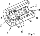
In der
Das Ventilgehäuse
Das Rückschlagventil weist ferner ein Schließelement
Wenn die Druckkraft der Mediumströmung die Druckkraft des Federelementes
Ein zweiter Querschnittsbereich
In den
Der Ventilanschlag
Zum Halten der Druckfeder weist der Einsatz
In Radialrichtung wird das Schließelement
Der gezeigte, über der Längsachse
Aufgrund der gewählten Konstruktion können die Einzelteile in verschiedenen Größen und insbesondere mit unterschiedlichen Strömungsquerschnitten bei gleichbleibendem Außendurchmesser, beispielsweise im selben Kunststoffwerkzeug, hergestellt werden, wobei ein Baukastensystem zum Einsatz kommen kann. Das Baukastensystem weist beispielsweise eine Vielzahl von Einsätzen
Auch das Schließelement
Aus dem Baukastensystem muss demnach nur ein geeignetes Schließelement
Das Zusammenfügen des Rückschlagventils kann beispielsweise gemäß einem Herstellungsverfahren erfolgen, bei welchem das Federelement
Wie man sieht, ist das Rückschlagventil insbesondere frei von jeglichen Verschraubungen, Vernietungen oder Verstiftungen. Alle Bauteile können ausschließlich formschlüssig ineinander gehalten und ausschließlich durch Einstecken und Umbiegen aneinander befestigt werden.As you can see, the check valve is in particular free from any screwing, riveting or pinning. All components can only be held in a form-fitting manner and fastened to each other exclusively by inserting and bending.
Selbstverständlich sind alternative Ausgestaltungen des Rückschlagventils denkbar. Nur beispielsweise sei angemerkt, dass alternativ oder zusätzlich zu den Einkerbungen
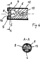
In der
Um das Schließelement
Die beschriebene konische Öffnung kann anders als dargestellt gestaltet sein, beispielsweise mit einer gekrümmten Oberfläche in Axialrichtung oder mit einer Verjüngung, die sich nur über einem Teil ihres Umfangs erstreckt, beispielsweise einer einseitigen Verjüngung. Andere Formen sind vorstellbar.The described conical opening may be designed differently than illustrated, for example with a curved surface in the axial direction or with a taper that extends only over part of its circumference, for example a one-sided taper. Other forms are conceivable.
Ein erfindungsgemäß ausgeführtes Rückschlagventil kann beispielsweise in einer Zuleitung für Öl oder einem anderen Medium, beispielsweise Wasser, zu einem Aggregat in einem Ölkreislauf oder anderen Mediumskreislauf in einem Kraftfahrzeug angeordnet sein. Das Aggregat kann beispielsweise eine hydrodynamische Maschine, beispielsweise eine hydrodynamische Kupplung, sein, wobei das Öl oder das Wasser das Arbeitsmedium der hydrodynamischen Maschine ist.A non-return valve according to the invention can be arranged, for example, in a supply line for oil or another medium, for example water, to form an aggregate in an oil circuit or other medium circuit in a motor vehicle. The unit may be, for example, a hydrodynamic machine, for example a hydrodynamic coupling, wherein the oil or the water is the working medium of the hydrodynamic machine.
Claims (17)
Priority Applications (2)
| Application Number | Priority Date | Filing Date | Title |
|---|---|---|---|
| DE200610051857 DE102006051857B4 (en) | 2006-10-31 | 2006-10-31 | check valve |
| PCT/EP2007/009493 WO2008052782A1 (en) | 2006-10-31 | 2007-10-31 | Non-return valve |
Applications Claiming Priority (1)
| Application Number | Priority Date | Filing Date | Title |
|---|---|---|---|
| DE200610051857 DE102006051857B4 (en) | 2006-10-31 | 2006-10-31 | check valve |
Publications (2)
| Publication Number | Publication Date |
|---|---|
| DE102006051857A1 DE102006051857A1 (en) | 2008-05-15 |
| DE102006051857B4 true DE102006051857B4 (en) | 2012-01-26 |
Family
ID=39167426
Family Applications (1)
| Application Number | Title | Priority Date | Filing Date |
|---|---|---|---|
| DE200610051857 Expired - Fee Related DE102006051857B4 (en) | 2006-10-31 | 2006-10-31 | check valve |
Country Status (2)
| Country | Link |
|---|---|
| DE (1) | DE102006051857B4 (en) |
| WO (1) | WO2008052782A1 (en) |
Families Citing this family (4)
| Publication number | Priority date | Publication date | Assignee | Title |
|---|---|---|---|---|
| DE102011102808A1 (en) * | 2010-06-21 | 2011-12-22 | Schaeffler Technologies Gmbh & Co. Kg | connecting element |
| DE202011003322U1 (en) | 2011-02-28 | 2012-05-30 | Alligator Ventilfabrik Gmbh | Residual pressure valve |
| DE102018100234B3 (en) * | 2018-01-08 | 2019-03-07 | Schaeffler Technologies AG & Co. KG | Throttle device with adjustable diaphragm element; Actuating device and coupling |
| CN113454327B (en) * | 2019-02-20 | 2023-06-06 | 皮尔伯格有限责任公司 | Flow restrictor for fuel shut-off valve |
Citations (6)
| Publication number | Priority date | Publication date | Assignee | Title |
|---|---|---|---|---|
| US2353161A (en) * | 1941-12-30 | 1944-07-11 | Specialties Dev Corp | Flotation apparatus |
| AT258063B (en) * | 1962-09-17 | 1967-11-10 | Benkiser Werk Kommandit Ges | Flow control valve with a throttle device that can move under flow pressure counter to spring action |
| DE2307790A1 (en) * | 1972-02-17 | 1973-08-23 | Hansen Mfg Company | SAFETY VALVE DEVICE |
| JPH0735251A (en) * | 1993-07-16 | 1995-02-07 | Suzuki Motor Corp | Check valve and canister system provided with same check valve |
| DE19754566A1 (en) * | 1997-12-09 | 1999-06-10 | Wildfang Dieter Gmbh | Backflow prevention valve for water supply |
| US6199583B1 (en) * | 1999-10-21 | 2001-03-13 | Fulvio Iacovella | Safety gas valve |
Family Cites Families (5)
| Publication number | Priority date | Publication date | Assignee | Title |
|---|---|---|---|---|
| US4345593A (en) * | 1978-07-19 | 1982-08-24 | A-T-O Inc. | Pressure-demand breathing apparatus with automatic air shut-off |
| DE9316306U1 (en) * | 1993-10-27 | 1993-12-16 | Schaeffler Waelzlager Kg | Throttle valve |
| GB9509407D0 (en) * | 1995-05-10 | 1995-07-05 | Macdonald Couplings Ltd | "Shut-off valve" |
| US7225810B2 (en) * | 2002-01-11 | 2007-06-05 | Hamai Industries Limited | Valve for use in high pressure gas containers |
| DE102005021743A1 (en) * | 2004-05-15 | 2005-12-08 | Luk Lamellen Und Kupplungsbau Beteiligungs Kg | Hydraulic mechanism e.g. for clutch, has take up cylinder and master cylinder, with fluid connecting line hydraulically connected between them with screen body having central shaft for pressure reduction |
-
2006
- 2006-10-31 DE DE200610051857 patent/DE102006051857B4/en not_active Expired - Fee Related
-
2007
- 2007-10-31 WO PCT/EP2007/009493 patent/WO2008052782A1/en active Application Filing
Patent Citations (6)
| Publication number | Priority date | Publication date | Assignee | Title |
|---|---|---|---|---|
| US2353161A (en) * | 1941-12-30 | 1944-07-11 | Specialties Dev Corp | Flotation apparatus |
| AT258063B (en) * | 1962-09-17 | 1967-11-10 | Benkiser Werk Kommandit Ges | Flow control valve with a throttle device that can move under flow pressure counter to spring action |
| DE2307790A1 (en) * | 1972-02-17 | 1973-08-23 | Hansen Mfg Company | SAFETY VALVE DEVICE |
| JPH0735251A (en) * | 1993-07-16 | 1995-02-07 | Suzuki Motor Corp | Check valve and canister system provided with same check valve |
| DE19754566A1 (en) * | 1997-12-09 | 1999-06-10 | Wildfang Dieter Gmbh | Backflow prevention valve for water supply |
| US6199583B1 (en) * | 1999-10-21 | 2001-03-13 | Fulvio Iacovella | Safety gas valve |
Also Published As
| Publication number | Publication date |
|---|---|
| DE102006051857A1 (en) | 2008-05-15 |
| WO2008052782A1 (en) | 2008-05-08 |
Similar Documents
| Publication | Publication Date | Title |
|---|---|---|
| EP2960561B1 (en) | Hydraulic valve | |
| EP2245276B1 (en) | Hydraulic control valve having integrated check valve | |
| DE102010032251A1 (en) | Check valve and hydraulic valve with built-in check valve | |
| DE102004061800A1 (en) | Injector of a fuel injection system of an internal combustion engine | |
| DE102004035035A1 (en) | Combustion engine camshaft positioner has at least a non-return valve in its hydraulic oil supply lines or in the connection area for the supply lines | |
| EP1600627A1 (en) | Control valve | |
| DE102011003556A1 (en) | Device for changing the relative angular position of a camshaft relative to a crankshaft of an internal combustion engine | |
| DE102006051857B4 (en) | check valve | |
| WO2011079980A1 (en) | Solenoid valve | |
| DE102011013176B4 (en) | Mechanically unlockable check valve with pressure relief | |
| DE102010064114B4 (en) | Pump with a throttle | |
| DE202010006605U1 (en) | central valve | |
| EP3015662B1 (en) | Hydraulic valve and a tilt motor adjuster | |
| EP2113698A2 (en) | Seat valve | |
| DE102007051407A1 (en) | Valve and method of manufacture of a valve | |
| DE102012208808A1 (en) | Control valve for controlling pressure medium flow of camshaft adjusting device, has radial bores which are spaced apart from each other in control sleeve and formed with greater diameter than the width of inner annular groove | |
| WO2007104391A1 (en) | Hydraulic valve arrangement | |
| DE102010039657B4 (en) | Bypass valve for regulating a fluid flow, for example in a fixed displacement pump | |
| DE202004004609U1 (en) | Pressure relief valve | |
| DE102011086160A1 (en) | Hydraulic clamping apparatus i.e. chain clamping apparatus, for chain drive of combustion engine, has throttle channel arranged within piston, where flow cross-section of channel is continuously reducible through closure element | |
| EP3421758B1 (en) | Switching module for controlling a hydraulic fluid stream of a connecting rod for a combustion engine with variable compression and connecting rod | |
| DE112008003332B4 (en) | Hydrostatic device or hydrostatic machine, in particular axial piston machine, with a valve arrangement in interchangeable valve construction with a filter | |
| DE102017206607A1 (en) | overflow | |
| DE102019100949B4 (en) | Sleeve for a swivel motor adjuster for a camshaft and a swivel motor adjuster for a camshaft | |
| DE102008007044B4 (en) | starter |
Legal Events
| Date | Code | Title | Description |
|---|---|---|---|
| OP8 | Request for examination as to paragraph 44 patent law | ||
| 8127 | New person/name/address of the applicant |
Owner name: VOITH PATENT GMBH, 89522 HEIDENHEIM, DE Owner name: SCHAEFFLER TECHNOLOGIES GMBH & CO. KG, 91074 H, DE |
|
| 8127 | New person/name/address of the applicant |
Owner name: VOITH PATENT GMBH, 89522 HEIDENHEIM, DE |
|
| R081 | Change of applicant/patentee |
Owner name: VOITH PATENT GMBH, DE Free format text: FORMER OWNERS: SCHAEFFLER TECHNOLOGIES GMBH & CO. KG, 91074 HERZOGENAURACH, DE; VOITH PATENT GMBH, 89522 HEIDENHEIM, DE Effective date: 20110304 Owner name: VOITH PATENT GMBH, DE Free format text: FORMER OWNER: SCHAEFFLER TECHNOLOGIES GMBH & , VOITH PATENT GMBH, , DE Effective date: 20110304 |
|
| R016 | Response to examination communication | ||
| R016 | Response to examination communication | ||
| R018 | Grant decision by examination section/examining division | ||
| R020 | Patent grant now final |
Effective date: 20120427 |
|
| R119 | Application deemed withdrawn, or ip right lapsed, due to non-payment of renewal fee |
Effective date: 20130501 |