DE102006047414B4 - Hard coating and process for its production - Google Patents
Hard coating and process for its production Download PDFInfo
- Publication number
- DE102006047414B4 DE102006047414B4 DE102006047414A DE102006047414A DE102006047414B4 DE 102006047414 B4 DE102006047414 B4 DE 102006047414B4 DE 102006047414 A DE102006047414 A DE 102006047414A DE 102006047414 A DE102006047414 A DE 102006047414A DE 102006047414 B4 DE102006047414 B4 DE 102006047414B4
- Authority
- DE
- Germany
- Prior art keywords
- hard coating
- coating film
- formula
- atomic ratio
- evaporation
- Prior art date
- Legal status (The legal status is an assumption and is not a legal conclusion. Google has not performed a legal analysis and makes no representation as to the accuracy of the status listed.)
- Expired - Fee Related
Links
Images

Classifications
-
- C—CHEMISTRY; METALLURGY
- C23—COATING METALLIC MATERIAL; COATING MATERIAL WITH METALLIC MATERIAL; CHEMICAL SURFACE TREATMENT; DIFFUSION TREATMENT OF METALLIC MATERIAL; COATING BY VACUUM EVAPORATION, BY SPUTTERING, BY ION IMPLANTATION OR BY CHEMICAL VAPOUR DEPOSITION, IN GENERAL; INHIBITING CORROSION OF METALLIC MATERIAL OR INCRUSTATION IN GENERAL
- C23C—COATING METALLIC MATERIAL; COATING MATERIAL WITH METALLIC MATERIAL; SURFACE TREATMENT OF METALLIC MATERIAL BY DIFFUSION INTO THE SURFACE, BY CHEMICAL CONVERSION OR SUBSTITUTION; COATING BY VACUUM EVAPORATION, BY SPUTTERING, BY ION IMPLANTATION OR BY CHEMICAL VAPOUR DEPOSITION, IN GENERAL
- C23C14/00—Coating by vacuum evaporation, by sputtering or by ion implantation of the coating forming material
- C23C14/06—Coating by vacuum evaporation, by sputtering or by ion implantation of the coating forming material characterised by the coating material
- C23C14/0664—Carbonitrides
-
- C—CHEMISTRY; METALLURGY
- C23—COATING METALLIC MATERIAL; COATING MATERIAL WITH METALLIC MATERIAL; CHEMICAL SURFACE TREATMENT; DIFFUSION TREATMENT OF METALLIC MATERIAL; COATING BY VACUUM EVAPORATION, BY SPUTTERING, BY ION IMPLANTATION OR BY CHEMICAL VAPOUR DEPOSITION, IN GENERAL; INHIBITING CORROSION OF METALLIC MATERIAL OR INCRUSTATION IN GENERAL
- C23C—COATING METALLIC MATERIAL; COATING MATERIAL WITH METALLIC MATERIAL; SURFACE TREATMENT OF METALLIC MATERIAL BY DIFFUSION INTO THE SURFACE, BY CHEMICAL CONVERSION OR SUBSTITUTION; COATING BY VACUUM EVAPORATION, BY SPUTTERING, BY ION IMPLANTATION OR BY CHEMICAL VAPOUR DEPOSITION, IN GENERAL
- C23C14/00—Coating by vacuum evaporation, by sputtering or by ion implantation of the coating forming material
- C23C14/22—Coating by vacuum evaporation, by sputtering or by ion implantation of the coating forming material characterised by the process of coating
- C23C14/34—Sputtering
- C23C14/3464—Sputtering using more than one target
-
- C—CHEMISTRY; METALLURGY
- C23—COATING METALLIC MATERIAL; COATING MATERIAL WITH METALLIC MATERIAL; CHEMICAL SURFACE TREATMENT; DIFFUSION TREATMENT OF METALLIC MATERIAL; COATING BY VACUUM EVAPORATION, BY SPUTTERING, BY ION IMPLANTATION OR BY CHEMICAL VAPOUR DEPOSITION, IN GENERAL; INHIBITING CORROSION OF METALLIC MATERIAL OR INCRUSTATION IN GENERAL
- C23C—COATING METALLIC MATERIAL; COATING MATERIAL WITH METALLIC MATERIAL; SURFACE TREATMENT OF METALLIC MATERIAL BY DIFFUSION INTO THE SURFACE, BY CHEMICAL CONVERSION OR SUBSTITUTION; COATING BY VACUUM EVAPORATION, BY SPUTTERING, BY ION IMPLANTATION OR BY CHEMICAL VAPOUR DEPOSITION, IN GENERAL
- C23C28/00—Coating for obtaining at least two superposed coatings either by methods not provided for in a single one of groups C23C2/00 - C23C26/00 or by combinations of methods provided for in subclasses C23C and C25C or C25D
- C23C28/04—Coating for obtaining at least two superposed coatings either by methods not provided for in a single one of groups C23C2/00 - C23C26/00 or by combinations of methods provided for in subclasses C23C and C25C or C25D only coatings of inorganic non-metallic material
- C23C28/044—Coating for obtaining at least two superposed coatings either by methods not provided for in a single one of groups C23C2/00 - C23C26/00 or by combinations of methods provided for in subclasses C23C and C25C or C25D only coatings of inorganic non-metallic material coatings specially adapted for cutting tools or wear applications
-
- C—CHEMISTRY; METALLURGY
- C23—COATING METALLIC MATERIAL; COATING MATERIAL WITH METALLIC MATERIAL; CHEMICAL SURFACE TREATMENT; DIFFUSION TREATMENT OF METALLIC MATERIAL; COATING BY VACUUM EVAPORATION, BY SPUTTERING, BY ION IMPLANTATION OR BY CHEMICAL VAPOUR DEPOSITION, IN GENERAL; INHIBITING CORROSION OF METALLIC MATERIAL OR INCRUSTATION IN GENERAL
- C23C—COATING METALLIC MATERIAL; COATING MATERIAL WITH METALLIC MATERIAL; SURFACE TREATMENT OF METALLIC MATERIAL BY DIFFUSION INTO THE SURFACE, BY CHEMICAL CONVERSION OR SUBSTITUTION; COATING BY VACUUM EVAPORATION, BY SPUTTERING, BY ION IMPLANTATION OR BY CHEMICAL VAPOUR DEPOSITION, IN GENERAL
- C23C28/00—Coating for obtaining at least two superposed coatings either by methods not provided for in a single one of groups C23C2/00 - C23C26/00 or by combinations of methods provided for in subclasses C23C and C25C or C25D
- C23C28/40—Coatings including alternating layers following a pattern, a periodic or defined repetition
- C23C28/42—Coatings including alternating layers following a pattern, a periodic or defined repetition characterized by the composition of the alternating layers
-
- C—CHEMISTRY; METALLURGY
- C23—COATING METALLIC MATERIAL; COATING MATERIAL WITH METALLIC MATERIAL; CHEMICAL SURFACE TREATMENT; DIFFUSION TREATMENT OF METALLIC MATERIAL; COATING BY VACUUM EVAPORATION, BY SPUTTERING, BY ION IMPLANTATION OR BY CHEMICAL VAPOUR DEPOSITION, IN GENERAL; INHIBITING CORROSION OF METALLIC MATERIAL OR INCRUSTATION IN GENERAL
- C23C—COATING METALLIC MATERIAL; COATING MATERIAL WITH METALLIC MATERIAL; SURFACE TREATMENT OF METALLIC MATERIAL BY DIFFUSION INTO THE SURFACE, BY CHEMICAL CONVERSION OR SUBSTITUTION; COATING BY VACUUM EVAPORATION, BY SPUTTERING, BY ION IMPLANTATION OR BY CHEMICAL VAPOUR DEPOSITION, IN GENERAL
- C23C30/00—Coating with metallic material characterised only by the composition of the metallic material, i.e. not characterised by the coating process
- C23C30/005—Coating with metallic material characterised only by the composition of the metallic material, i.e. not characterised by the coating process on hard metal substrates
-
- Y—GENERAL TAGGING OF NEW TECHNOLOGICAL DEVELOPMENTS; GENERAL TAGGING OF CROSS-SECTIONAL TECHNOLOGIES SPANNING OVER SEVERAL SECTIONS OF THE IPC; TECHNICAL SUBJECTS COVERED BY FORMER USPC CROSS-REFERENCE ART COLLECTIONS [XRACs] AND DIGESTS
- Y10—TECHNICAL SUBJECTS COVERED BY FORMER USPC
- Y10T—TECHNICAL SUBJECTS COVERED BY FORMER US CLASSIFICATION
- Y10T428/00—Stock material or miscellaneous articles
- Y10T428/12—All metal or with adjacent metals
- Y10T428/12493—Composite; i.e., plural, adjacent, spatially distinct metal components [e.g., layers, joint, etc.]
- Y10T428/12535—Composite; i.e., plural, adjacent, spatially distinct metal components [e.g., layers, joint, etc.] with additional, spatially distinct nonmetal component
- Y10T428/12576—Boride, carbide or nitride component
-
- Y—GENERAL TAGGING OF NEW TECHNOLOGICAL DEVELOPMENTS; GENERAL TAGGING OF CROSS-SECTIONAL TECHNOLOGIES SPANNING OVER SEVERAL SECTIONS OF THE IPC; TECHNICAL SUBJECTS COVERED BY FORMER USPC CROSS-REFERENCE ART COLLECTIONS [XRACs] AND DIGESTS
- Y10—TECHNICAL SUBJECTS COVERED BY FORMER USPC
- Y10T—TECHNICAL SUBJECTS COVERED BY FORMER US CLASSIFICATION
- Y10T428/00—Stock material or miscellaneous articles
- Y10T428/12—All metal or with adjacent metals
- Y10T428/12493—Composite; i.e., plural, adjacent, spatially distinct metal components [e.g., layers, joint, etc.]
- Y10T428/12736—Al-base component
- Y10T428/12743—Next to refractory [Group IVB, VB, or VIB] metal-base component
-
- Y—GENERAL TAGGING OF NEW TECHNOLOGICAL DEVELOPMENTS; GENERAL TAGGING OF CROSS-SECTIONAL TECHNOLOGIES SPANNING OVER SEVERAL SECTIONS OF THE IPC; TECHNICAL SUBJECTS COVERED BY FORMER USPC CROSS-REFERENCE ART COLLECTIONS [XRACs] AND DIGESTS
- Y10—TECHNICAL SUBJECTS COVERED BY FORMER USPC
- Y10T—TECHNICAL SUBJECTS COVERED BY FORMER US CLASSIFICATION
- Y10T428/00—Stock material or miscellaneous articles
- Y10T428/12—All metal or with adjacent metals
- Y10T428/12493—Composite; i.e., plural, adjacent, spatially distinct metal components [e.g., layers, joint, etc.]
- Y10T428/12771—Transition metal-base component
-
- Y—GENERAL TAGGING OF NEW TECHNOLOGICAL DEVELOPMENTS; GENERAL TAGGING OF CROSS-SECTIONAL TECHNOLOGIES SPANNING OVER SEVERAL SECTIONS OF THE IPC; TECHNICAL SUBJECTS COVERED BY FORMER USPC CROSS-REFERENCE ART COLLECTIONS [XRACs] AND DIGESTS
- Y10—TECHNICAL SUBJECTS COVERED BY FORMER USPC
- Y10T—TECHNICAL SUBJECTS COVERED BY FORMER US CLASSIFICATION
- Y10T428/00—Stock material or miscellaneous articles
- Y10T428/24—Structurally defined web or sheet [e.g., overall dimension, etc.]
- Y10T428/24942—Structurally defined web or sheet [e.g., overall dimension, etc.] including components having same physical characteristic in differing degree
- Y10T428/2495—Thickness [relative or absolute]
- Y10T428/24967—Absolute thicknesses specified
- Y10T428/24975—No layer or component greater than 5 mils thick
-
- Y—GENERAL TAGGING OF NEW TECHNOLOGICAL DEVELOPMENTS; GENERAL TAGGING OF CROSS-SECTIONAL TECHNOLOGIES SPANNING OVER SEVERAL SECTIONS OF THE IPC; TECHNICAL SUBJECTS COVERED BY FORMER USPC CROSS-REFERENCE ART COLLECTIONS [XRACs] AND DIGESTS
- Y10—TECHNICAL SUBJECTS COVERED BY FORMER USPC
- Y10T—TECHNICAL SUBJECTS COVERED BY FORMER US CLASSIFICATION
- Y10T428/00—Stock material or miscellaneous articles
- Y10T428/26—Web or sheet containing structurally defined element or component, the element or component having a specified physical dimension
- Y10T428/263—Coating layer not in excess of 5 mils thick or equivalent
- Y10T428/264—Up to 3 mils
- Y10T428/265—1 mil or less
Abstract
Harte Beschichtung mit einer durch die nachstehenden Formeln (3a) oder (3b) wiedergegebenen Zusammensetzung (Cr(1-p-q-r)AlpZrqHfr)(C(1-z)Nz)(3a)oder (Cr(1-p-q-s-t)AlpZrqHfrSisBt)(C(1-z)Nz)(3b)worin in Formel (3a) q und r gleich 0 sein können und folgende Beziehungen erfüllt sind: – für p < 0,5 gilt: 0,2 ≤ p < 0,5; 0,2 ≤ (q + r) ≤ 0,5; 0,05 ≤ (1 – p – q – r); 0,5 ≤ z ≤ 1 – für p ≥ 0,5 gilt: 0,5 ≤ p ≤ 0,7; 0,05 ≤ (q + r) ≤ 0,25; 0,15 ≤ (1 – p – q – r); 0,5 ≤ z ≤ 1 und in Formel (3b) q, r, s und t gleich 0 sein können und folgende Beziehungen erfüllt sind: – für p < 0,5 gilt: 0,2 ≤ p < 0,5; 0,2 ≤ (q + r) ≤ 0,5; 0 < (s + t) ≤ 0,2; 0,05 (1 – p – q – r...Hard coating having a composition represented by the following formula (3a) or (3b) (Cr (1-pqr) AlpZrqHfr) (C (1-z) Nz) (3a) or (Cr (1-pqst) AlpZrqHfrSisBt) (C. (1-z) Nz) (3b) where in formula (3a) q and r can be equal to 0 and the following relationships are fulfilled: for p <0.5 the following applies: 0.2 p <0.5; 0.2 (q + r) 0.5; 0.05 ≤ (1 - p - q - r); 0.5 ≤ z ≤ 1 - for p ≥ 0.5 the following applies: 0.5 ≤ p ≤ 0.7; 0.05 (q + r) 0.25; 0.15 ≤ (1 - p - q - r); 0.5 z 1 and in formula (3b) q, r, s and t can be equal to 0 and the following relationships are fulfilled: for p <0.5 the following applies: 0.2 p <0.5; 0.2 (q + r) 0.5; 0 <(s + t) ≤ 0.2; 0.05 (1 - p - q - r ...
Description
Hintergrund der ErfindungBackground of the invention
1. Gebiet der Erfindung:1. Field of the invention:
Die Erfindung betrifft eine harte Beschichtung und ein Verfahren zu deren Herstellung, die vorteilhafterweise auf Schneidwerkzeugen (wie Meißel, Bohrer und Stirnfräse) und Vorrichtungen (wie Schmiedegesenk und Stanzstempel) gebildet werden kann.The invention relates to a hard coating and a method for the production thereof, which can be advantageously formed on cutting tools (such as chisel, drill and face milling machine) and devices (such as forging die and punch).
2. Beschreibung des Standes der Technik:2. Description of the Related Art:
Übliche Schneidwerkzeuge, die zur verbesserten Verschleißbeständigkeit vorgesehen sind, bestehen aus einem Substrat von Hochgeschwindigkeitsstahl bzw. Schnellstahl, Zementcarbid bzw. Hartmetall, Cermet oder dergleichen und einer darauf gebildeten harten Beschichtung von TiN, TiCN, TiAlN und dergleichen. Von diesen harten Beschichtungen wird jene von TiAlN in günstiger Weise auf Schneidwerkzeuge zum Hochgeschwindigkeitsschneiden oder Hartwerkstoffe, wie gehärteter Stahl, aufgrund ihrer hohen Verschleißbeständigkeit aufgetragen. Der jüngste Trend zu härteren Werkstücken und höheren Schneidgeschwindigkeiten erfordert die Entwicklung von einer neuen harten Beschichtung mit besserer Verschleißbeständigkeit.Conventional cutting tools intended for improved wear resistance consist of a substrate of high-speed steel, cement carbide, cermet or the like and a hard coating of TiN, TiCN, TiAlN and the like formed thereon. Of these hard coatings, TiAlN is favorably applied to cutting tools for high speed cutting or hard materials such as hardened steel because of their high wear resistance. The recent trend towards harder workpieces and higher cutting speeds requires the development of a new hard coating with better wear resistance.
Ein Beispiel für jüngste Entwicklungen ist die Modifizierung von TiAlN zu TiCrAlN (durch teilweisen Ersatz von Ti gegen Cr), wie in Patentdokument 1 offenbart. Gemäß der Offenbarung erhöht zugegebenes Cr das Zusammensetzungsverhältnis von AlN von Steinsalzstruktur, wodurch es zur Härte und Oxidationsbeständigkeit der Beschichtung beiträgt. Ein weiteres Beispiel für jüngste Entwicklungen ist eine harte Beschichtung von CrAlN, die sich aus TiAlN durch den vollständigen Ersatz von Ti gegen Cr ergibt, wie in dem Patentdokument 2 offenbart.An example of recent developments is the modification of TiAlN to TiCrAlN (by partially replacing Ti with Cr) as disclosed in Patent Document 1. According to the disclosure, added Cr increases the composition ratio of AlN of rock salt structure, thereby contributing to the hardness and oxidation resistance of the coating. Another example of recent developments is a hard coating of CrAlN resulting from TiAlN by the complete replacement of Ti with Cr as disclosed in Patent Document 2.
-
Patentdokument 1:
Japanische Patent-Offenlegungsschrift Nr. 2003-71610 A Japanese Patent Laid-Open Publication No. 2003-71610 A -
Patentdokument 2:
Japanische Patent-Offenlegungsschrift Nr. Hei-9-41127 A Japanese Patent Laid-Open Publication No. Hei-9-41127A
Aufgabe und Kurzdarstellung der ErfindungTask and summary of the invention
Obwohl die vorstehend erwähnten harten Beschichtungen von TiAlN, TiCrAlN und AlCrN gute Oxidationsbeständigkeit bei hohen Temperaturen zeigen, neigen sie zur Abnahme in der Harte unter scharfen Bedingungen, die sehr hohe Temperaturen und intensive Gleitreibung einbeziehen (was von Hochgeschwindigkeitsschneiden im trockenen Zustand oder plastischem Arbeiten bei einem hohen Flächendruck stammt). In einigen Fällen unterliegen sie der Änderung der Kristallstruktur für einen Übergang in die weiche Phase. Deshalb weisen sie Raum zur Verbesserung in den Hochtemperatureigenschaften auf.Although the aforementioned hard coatings of TiAlN, TiCrAlN and AlCrN exhibit good oxidation resistance at high temperatures, they tend to decrease in hardness under severe conditions involving very high temperatures and intense sliding friction (resulting from high speed dry cutting or plastic working at high temperatures high surface pressure comes). In some cases they are subject to change of crystal structure for transition to the soft phase. Therefore, they have room for improvement in high temperature properties.
Die vorliegende Erfindung wurde im Hinblick auf das Vorangehende abgeschlossen. Es ist eine Aufgabe der vorliegenden Erfindung, eine harte Beschichtung mit verbesserten Hochtemperatureigenschaften bereitzustellen.The present invention has been completed in view of the foregoing. It is an object of the present invention to provide a hard coating having improved high temperature properties.
Um die vorstehend erwähnten Probleme anzugehen, führten die Erfinder eine Reihe von Untersuchungen aus, die zu der Erkenntnis führten, dass die vorstehend erwähnte Aufgabe gelöst wird, wenn ein Nitrid (CrAlN) oder Carbonitrid (CrAlCN) von CrAl in geeigneter Weise mit Zr oder Hf kombiniert wird. Die vorliegende Erfindung basiert auf dieser Erkenntnis.In order to address the above-mentioned problems, the inventors made a series of studies which led to the finding that the above-mentioned object is achieved when a nitride (CrAlN) or carbonitride (CrAlCN) of CrAl is suitably treated with Zr or Hf combined. The present invention is based on this finding.
Die vorliegende Erfindung ist auf eine harte Beschichtung mit einer durch die nachstehenden Formeln (3a) oder (3b) wiedergegebenen Zusammensetzung gerichtet
- – für p < 0,5 gilt: 0,2 ≤ p < 0,5; 0,2 ≤ (q + r) ≤ 0,5; 0,05 ≤ (1 – p – q – r); 0,5 ≤ z ≤ 1
- – für p ≥ 0,5 gilt: 0,5 ≤ p ≤ 0,7; 0,05 ≤ (q + r) ≤ 0,25; 0,15 ≤ (1 – p – q – r); 0,5 ≤ z ≤ 1
- – für p < 0,5 gilt: 0,2 ≤ p < 0,5; 0,2 ≤ (q + r) ≤ 0,5; 0 < (s + t) ≤ 0,2; 0,05 ≤ (1 – p – q – r – s – t); 0,5 ≤ z ≤ 1
- – für p ≥ 0,5 gilt: 0,5 ≤ p ≤ 0,7; 0,05 ≤ (q + r) ≤ 0,25; 0 < (s + t) ≤ 0,2; 0,15 ≤ (1 – p – q – r – s – t); 0,5 ≤ z ≤ 1.
- For p <0.5, 0.2 ≤ p <0.5; 0.2 ≤ (q + r) ≤ 0.5; 0.05 ≤ (1 - p - q - r); 0.5 ≤ z ≤ 1
- - for p ≥ 0.5: 0.5 ≤ p ≤ 0.7; 0.05 ≤ (q + r) ≤ 0.25; 0.15 ≤ (1-p-q-r); 0.5 ≤ z ≤ 1
- For p <0.5, 0.2 ≤ p <0.5; 0.2 ≤ (q + r) ≤ 0.5; 0 <(s + t) ≤0.2; 0.05 ≤ (1-p-q-r-s-t); 0.5 ≤ z ≤ 1
- - for p ≥ 0.5: 0.5 ≤ p ≤ 0.7; 0.05 ≤ (q + r) ≤ 0.25; 0 <(s + t) ≤0.2; 0.15 ≤ (1-p-q-r-s-t); 0.5 ≤ z ≤ 1.
Die vorstehend erwähnte harte Beschichtung wird durch Bilden einer Schicht von Nitrid oder Carbonitrid mit einem Kohlenstoff-Stickstoff-Atomverhältnis von 0,5 zu 0,5 bis 0 zu 1 durch Ionenplattieren oder Sputtern
- – für Formel (3a) mit einem Target der Formel
(Cr(1-p-q-r)AlpZrqHfr) (3c)
für p < 0,5 gilt: 0,2 ≤ p < 0,5; 0,2 ≤ (q + r) ≤ 0,5; 0,05 ≤ (1-p-q-r);
für p ≥ 0,5 gilt: 0,5 ≤ p ≤ 0,7; 0,05 ≤ (q + r) ≤ 0,25; 0,15 ≤ (1-p-q-r); und
- – für Formel (3b) mit einem Target der Formel
(Cr(1-p-q-r-s-t)AlpZrqHfrSisBt) (3d)
für p < 0,5 gilt: 0,2 ≤ p < 0,5; 0,2 ≤ (q + r) ≤ 0,5; 0 < (s + t) ≤ 0,2; 0,05 ≤ (1-p-q-r-s-t);
für p ≥ 0,5 gilt: 0,5 ≤ p ≤ 0,7; 0,05 ≤ (q + r) ≤ 0,25; 0 < (s + t) ≤ 0,2; 0,15 ≤ (1-p-q-r-s-t),
erhalten.The above hard coating is formed by forming a layer of nitride or carbonitride having a carbon-nitrogen atomic ratio of 0.5 to 0.5 to 0 to 1 by ion plating or sputtering
- For formula (3a) with a target of the formula
(Cr (1-pqr) Al p Zr q Hf r ) (3c)
for p <0.5: 0.2 ≤ p <0.5; 0.2 ≤ (q + r) ≤ 0.5; 0.05 ≤ (1-pqr);
for p ≥ 0.5: 0.5 ≤ p ≤ 0.7; 0.05 ≤ (q + r) ≤ 0.25; 0.15 ≤ (1-pqr); and
- For formula (3b) with a target of the formula
(Cr (1-pqrst) Al p Zr q Hf r Si s B t ) (3d)
for p <0.5: 0.2 ≤ p <0.5; 0.2 ≤ (q + r) ≤ 0.5; 0 <(s + t) ≤0.2; 0.05 ≤ (1-pqrst);
for p ≥ 0.5: 0.5 ≤ p ≤ 0.7; 0.05 ≤ (q + r) ≤ 0.25; 0 <(s + t) ≤0.2; 0.15 ≤ (1-pqrst),
receive.
Die vorstehend erwähnte harte Beschichtung sollte vorzugsweise eine kubische Kristallstruktur besitzen.The above-mentioned hard coating should preferably have a cubic crystal structure.
Die erfindungsgemäße harte Beschichtung hat vorzugsweise eine Dicke von nicht kleiner als 1000 nm.The hard coating of the invention preferably has a thickness of not smaller than 1000 nm.
<Wirkung der Erfindung><Effect of the invention>
Die erfindungsgemäße harte Beschichtung hat verbesserte Hochtemperatureigenschaften, weil sie aus CrAl in ihrer Nitrid (CrAlN)- oder Carbonitrid (CrAlCN)-Form, in geeigneter Weise mit Zr und/oder Hf kombiniert, hergestellt wird. Das Nitrid oder Carbonitrid wird nachstehend insgesamt als (Carbo)nitrid bezeichnet.The hard coating of the present invention has improved high temperature properties because it is made of CrAl in its nitride (CrAlN) or carbonitride (CrAlCN) form suitably combined with Zr and / or Hf. The nitride or carbonitride is hereinafter referred to collectively as (carbo) nitride.
Kurzbeschreibung der ZeichnungenBrief description of the drawings
Die erfindungsgemäße harte Beschichtung wird aus einem (Carbo)nitrid von CrAl, das in geeigneter Weise mit Zr und/oder Hf kombiniert wurde, gebildet. Diese Ausführungsform ist für eine harte Beschichtung vom Einzelschichttyp entwickelt worden, die aus einem (Carbo)nitrid von CrAl, kombiniert mit Zr und/oder Hf, gebildet wird. Diese harte Beschichtung wird nachstehend hierin als ein einschichtiger harter Beschichtungsfilm bezeichnet. Das (Carbo)nitrid, aus dem der einschichtige harte Beschichtungsfilm gebildet wird, wird hierin nachstehend als CrAlZrHf (Carbo)nitrid bezeichnet. (Carbo)nitride von Zr und Hf haben eine größere negative freie Bildungsenergie als (Carbo)nitride von Ti und Cr. Deshalb wird ein (Carbo)nitrid von CrAl in der Hochtemperaturstabilität, Hochtemperaturhärte und Verschleißbeständigkeit verbessert, wenn es mit einem (Carbo)nitrid von Zr oder Hf laminiert wird oder dieses darin eingearbeitet wird. The hard coating according to the invention is formed from a (carbo) nitride of CrAl, which has been suitably combined with Zr and / or Hf. This embodiment has been developed for a single layer type hard coating formed of a (carbo) nitride of CrAl combined with Zr and / or Hf. This hard coating will hereinafter be referred to as a single-layered hard coating film. The (carbo) nitride from which the single-layer hard coating film is formed will hereinafter be referred to as CrAlZrHf (carbo) nitride. (Carbo) nitrides of Zr and Hf have a greater negative free energy of formation than (carbo) nitrides of Ti and Cr. Therefore, a (carbo) nitride of CrAl in high-temperature stability, high-temperature hardness and wear resistance is improved when it is laminated with or incorporated with a (carbo) nitride of Zr or Hf.
Außerdem können das (Carbo)nitrid von CrAl, das (Carbo)nitrid von Zr und/oder Hf und das (Carbo)nitrid von CrAlZrHf auch mit Si und/oder B eingearbeitet werden. Die so zugesetzten Si und B verbessern weiterhin die Oxidationsbeständigkeit des harten Beschichtungsfilms und tragen zu der Bildung von feinen Kristallkörnern in dem harten Beschichtungsfilm bei.In addition, the (carbo) nitride of CrAl, the (carbo) nitride of Zr and / or Hf and the (carbo) nitride of CrAlZrHf can also be incorporated with Si and / or B. The thus added Si and B further improve the oxidation resistance of the hard coating film and contribute to the formation of fine crystal grains in the hard coating film.
Nachstehend erfolgt eine genauere Beschreibung des erfindungsgemäßen harten Beschichtungsfilms.Hereinafter, a more detailed description will be given of the hard coating film of the present invention.
<Harter Beschichtungsfilm vom Einzelschichttyp><Single-layer type hard coating film>
Der erfindungsgemäße harte Beschichtungsfilm vom Einzelschichttyp wird aus einem (Carbo)nitrid von CrAlZrHf (der durch Zusatz von Zr und/oder Hf zu (Carbo)nitrid von CrAl erhalten wird) gebildet. Insbesondere hat der harte Beschichtungsfilm vom Einzelschichttyp eine durch die nachstehende Formel (3a) wiedergegebene Zusammensetzung.
wenn p < 0,5:
if p <0.5:
In der vorstehend genannten Formel (3a) bedeutet der tiefgestellte Index p das Atomverhältnis von Al. Der Wert von p sollte größer als der Minimumwert sein, weil Al für die Härte und Oxidationsbeständigkeit wesentlich ist. Jedoch wird mit einem zu großem Wert von p der erhaltene harte Beschichtungsfilm in der Regel die hexagonale Struktur annehmen (die weich ist). Deshalb sollte das Atomverhältnis von Al nicht kleiner als 0,2, vorzugsweise nicht kleiner als 0,25, bevorzugter nicht kleiner als 0,3 und nicht größer als 0,7, vorzugsweise nicht größer als 0,65, bevorzugter nicht größer als 0,6, sein.In the above formula (3a), the subscript p means the atomic ratio of Al. The value of p should be greater than the minimum value because Al is essential for hardness and oxidation resistance. However, if the value of p is too large, the obtained hard coating film will tend to adopt the hexagonal structure (which is soft). Therefore, the atomic ratio of Al should not be smaller than 0.2, preferably not smaller than 0.25, more preferably not smaller than 0.3 and not larger than 0.7, preferably not larger than 0.65, more preferably not larger than 0, 6, his.
In der vorstehend genannten Formel haben das Gesamtatomverhältnis (q + r) für Zr und Hf und das Atomverhältnis (1 – p – q – r) für Cr unterschiedliche Bereiche in Abhängigkeit von dem Atomverhältnis (p) für Al. Wenn das Atomverhältnis (p) für Al kleiner als 0,5 ist, ist es notwendig, ausreichend Zr und/oder Hf zuzusetzen, um die Rolle von Al zu kompensieren (für Härte und Oxidationsbeständigkeit). Wenn andererseits das Atomverhältnis (p) für Al nicht kleiner als 0,5 ist, sollte die Menge an Zr und/oder Hf vermindert werden, weil zu viel Zr und/oder Hf die Kristallstruktur zur hexagonalen ändert. Das Atomverhältnis (1 – q – p – r) für Cr wird gemäß dem Gesamtatomverhältnis (q + r) für Zr und Hf und den erforderlichen Filmeigenschaften bestimmt. Die nachstehenden Regeln sind auf das Gesamtatomverhältnis (q + r) für Zr und Hf und das Atomverhältnis (1 – q – p – r) für Cr anwendbar.
- (1) Wenn das Atomverhältnis (p) für Al kleiner als 0,5 ist.
- (1) When the atomic ratio (p) for Al is less than 0.5.
Das Gesamtatomverhältnis (q + r) für Zr und Hf sollte nicht kleiner als 0,2, vorzugsweise nicht kleiner als 0,23, bevorzugter nicht kleiner als 0,25 und nicht größer als 0,5, vorzugsweise nicht größer als 0,47, bevorzugter nicht größer als 0,45, sein.The total atomic ratio (q + r) for Zr and Hf should not be smaller than 0.2, preferably not smaller than 0.23, more preferably not smaller than 0.25 and not larger than 0.5, preferably not larger than 0.47, more preferably not greater than 0.45.
Das Atomverhältnis (1 – q – p – r) für Cr sollte nicht kleiner als 0,05, vorzugsweise nicht kleiner als 0,1, bevorzugter nicht kleiner als 0,15, sein.
- (2) Wenn das Atomverhältnis (p) für Al nicht kleiner als 0,5 ist.
- (2) When the atomic ratio (p) for Al is not less than 0.5.
Das Gesamtatomverhältnis (q + r) für Zr und Hf sollte nicht kleiner als 0,05, vorzugsweise nicht kleiner als 0,08, bevorzugter nicht kleiner als 0,1 und nicht größer als 0,25, vorzugsweise nicht größer als 0,22, bevorzugter nicht größer als 0,2, sein.The total atomic ratio (q + r) for Zr and Hf should not be smaller than 0.05, preferably not smaller than 0.08, more preferably not smaller than 0.1 and not larger than 0.25, preferably not larger than 0.22, more preferably not greater than 0.2.
Das Atomverhältnis (1 – q – p – r) für Cr sollte nicht kleiner als 0,15, bevorzugter nicht kleiner als 0,2, sein.The atomic ratio (1-q-p-r) for Cr should not be less than 0.15, more preferably not less than 0.2.
Es ist möglich, ungeachtet des Bereichs von dem Atomverhältnis (p) für Al, einen oder beide von Zr und Hf zuzugeben. Deshalb kann jeder von q und r 0 sein.It is possible to add one or both of Zr and Hf regardless of the range of the atomic ratio (p) for Al. Therefore, each of q and r can be 0.
Das Atomverhältnis (z) für N sollte, ungeachtet des Bereichs des Atomverhältnis (p) für Al, 0,5 zu 1, vorzugsweise 0,8 zu 1, sein, da eine Abnahme im Atomverhältnis (z) von N zu einer Erhöhung im Atomverhältnis von C führt, was eine instabile Verbindung von AlC3 ergibt.The atomic ratio (z) for N, irrespective of the range of the atomic ratio (p) for Al, should be 0.5 to 1, preferably 0.8 to 1, since a decrease in atomic ratio (z) of N to an increase in atomic ratio leads from C, resulting in an unstable connection of AlC 3 .
Der harte Beschichtungsfilm vom Einzelschichttyp kann zusätzlich Si und/oder B enthalten. Der harte Beschichtungsfilm vom Einzelschichttyp, der Si und/oder B enthält, hat eine durch die nachstehende Formel (3b) wiedergegebene Zusammensetzung, in der B ein Carbonitrid bilden kann oder B auch ein Borid mit Cr, Al, Zr, Hf und Si bilden kann.
wenn p < 0,5:
if p <0.5:
Das Atomverhältnis (p) für Al, das Gesamtatomverhältnis (q + r) für Zr und Hf und das Atomverhältnis (z) für N sind aus dem gleichen Grund wie die vorstehende Formel (3a) ausgewiesen. Das Atomverhältnis (1 – q – p – r – s – t) für Cr ist aus dem gleichen Grund wie das Atomverhältnis (1 – q – p – r) für Cr in der vorstehenden Formel (3a) ausgewiesen. The atomic ratio (p) for Al, the total atomic ratio (q + r) for Zr and Hf and the atomic ratio (z) for N are shown for the same reason as the above formula (3a). The atomic ratio (1-q-p-r-s-t) for Cr is shown for the same reason as the atomic ratio (1-q-p-r) for Cr in the above formula (3a).
Das zusätzliche Si und/oder B bilden die Si-N-Bindung oder B-N-Bindung an der Korngrenze, wodurch das Kristallwachstum abnimmt und ergeben feine Kristalle, die zu einer verbesserten Härte führen. Sie können auch zur Oxidationsbeständigkeit beitragen (obwohl dies noch nicht aufgeklärt ist).The additional Si and / or B form the Si-N bond or B-N bond at the grain boundary, thereby decreasing crystal growth and giving fine crystals leading to improved hardness. They may also contribute to oxidation resistance (although this has not been elucidated yet).
Eines oder beide von Si oder B können zugesetzt werden. Deshalb kann jede der Variablen s und t gleich Null sein. Da Silizium dem Bor in der Oxidationsbeständigkeit überlegen ist, ist es erwünscht, mehr Si als B zuzusetzen, wenn Oxidationsbeständigkeit wichtig ist (oder es erwünschter ist, nur Si zuzusetzen). Da B andererseits die B-N-Bindung zum Gleiten bildet, ist es erwünscht, mehr B als Si zuzusetzen, wenn Gleitfähigkeit wichtig ist (oder es ist erwünschter, nur B zuzusetzen).One or both of Si or B may be added. Therefore, each of the variables s and t can be equal to zero. Since silicon is superior to boron in oxidation resistance, it is desirable to add more Si than B when oxidation resistance is important (or it is more desirable to add only Si). On the other hand, as B forms the B-N bond to slip, it is desirable to add more B than Si when lubricity is important (or it is more desirable to add only B).
Der harte Beschichtungsfilm vom Einzelschichttyp kann beispielsweise durch chemische Dampfabscheidung (CVD) oder physikalische Dampfabscheidung (PVD), insbesondere Sputtern und Ionenplattieren (Bogenionenplattieren), gebildet werden.The single layer type hard coating film may be formed by, for example, chemical vapor deposition (CVD) or physical vapor deposition (PVD), in particular, sputtering and ion plating (arc ion plating).
Der harte Beschichtungsfilm vom Einzelschichttyp kann durch PVD von dem nachstehend durch die Formel (3c) oder (3d) wiedergegebenen Target gebildet werden, welches eine (Carbo)nitridschicht mit einem C/N-Atomverhältnis von 0,5/0,5 bis 0/1 ergibt.
Bevorzugte filmbildende Verfahren sind Sputtern und Ionenplattierung, worin die Verdampfungsgeschwindigkeit von Elementen in dem Target nicht stark von ihrem Schmelzpunkt abhängt. Die Filmbildung durch Ionenstrahlabscheidung und Hohlkathodenabscheidung wirft Schwierigkeiten beim Steuern der Verdampfungsmenge von jedem Element in dem Target auf.Preferred film-forming processes are sputtering and ion plating, wherein the rate of evaporation of elements in the target does not strongly depend on their melting point. Film formation by ion beam deposition and hollow cathode deposition poses difficulties in controlling the evaporation amount of each element in the target.
Ionenplattierung (insbesondere Bogenionenplattierung) übertrifft das Sputtern (insbesondere nicht ausgeglichenes Magnetronensputtern (UBMS)) in der Filmbildungsgeschwindigkeit. Jedoch ist Sputtern dem Ionenplattieren beim leichten Entladen, leichter Dickekontrolle und seltenem Targetbruch überlegen. Diese Eigenschaften können verwendet werden, um ein hinreichendes Filmbildungsverfahren auszuwählen. Beispielsweise ist Sputtern zur Abscheidung geeignet, die ein Target anwendet, das Zr und/oder Hf enthält, weil Ionenplattierung Schwierigkeiten beim Entladen aufwirft. Ausgenommen für das vorangehend Genannte wird für bessere Herstellungswirksamkeit Ionenplattierung empfohlen.Ion plating (in particular, arc ion plating) outperforms sputtering (especially unbalanced magnetron sputtering (UBMS)) in the film formation rate. However, sputtering is superior to ion plating in light unloading, light thickness control and rare target breakage. These properties can be used to select a sufficient film formation process. For example, sputtering is suitable for deposition employing a target containing Zr and / or Hf because ion plating poses difficulty in discharging. Except for the foregoing, ion plating is recommended for better manufacturing efficiency.
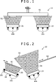
Das Verfahren zum Bilden des harten Beschichtungsfilms durch Sputtern (insbesondere UBMS) oder Ionenplattierung (insbesondere Bogenionenplattierung) wird genauer mit Bezug auf die beigefügten Zeichnungen beschrieben.The method of forming the hard coating film by sputtering (especially, UBMS) or ion plating (in particular, arc ion plating) will be described in detail with reference to the accompanying drawings.
Die gleiche Funktion wie Schieberöffnen und -schließen, kann durch An- und Ausstellen der Entladung der Verdampfungsquellen ausgeführt werden, um den harten Beschichtungsfilm herzustellen.The same function as slide opening and closing can be performed by turning on and off the discharge of the evaporation sources to prepare the hard coating film.
Die in
Auch können die in
Außerdem erlauben die in
Die in
Eine Reihe von Verdampfungsquellen besteht aus Targets und die andere Reihe der Verdampfungsquellen besteht aus Targets. Diese Targets werden in ein filmbildendes Gas verdampft, das ein N-enthaltendes Gas, ein Gemisch von N-enthaltendem Gas und C-enthaltendem Gas und das vorangehende Gas, verdünnt mit einem Inertgas, einschließt. Wenn sich die Drehplatte
Die in
Die in
Der harte Beschichtungsfilm vom Einzelschichttyp sollte vorzugsweise eine kubische Kristallstruktur aufweisen.The single layer type hard coating film should preferably have a cubic crystal structure.
Gemäß der vorliegenden Erfindung sollte der harte Beschichtungsfilm eine Dicke nicht kleiner als 1000 nm, vorzugsweise nicht kleiner 2000 nm und nicht größer als 10000 nm, vorzugsweise nicht größer als 5000 nm, aufweisen.According to the present invention, the hard coating film should have a thickness not smaller than 1000 nm, preferably not smaller than 2000 nm and not larger than 10000 nm, preferably not larger than 5000 nm.
Der erfindungsgemäße harte Beschichtungsfilm hat aufgrund der Kombination von (Carbo)nitrid von CrAl (wiedergegeben durch CrAlCN und CrAlN) und Zr und/oder Hf stark verbesserte Hochtemperatureigenschaften.The hard coating film of the present invention has highly improved high-temperature properties due to the combination of (carbo) nitride of CrAl (represented by CrAlCN and CrAlN) and Zr and / or Hf.
BeispieleExamples
Die Erfindung wird genauer mit Bezug auf die nachstehenden Beispiele beschrieben, die nicht vorgesehen sind, deren Umfang darauf zu begrenzen. Verschiedene Veränderungen und Modifizierungen können in der vorliegenden Erfindung erfolgen, ohne vom Geist und Umfang davon abzuweichen.The invention will be described in more detail with reference to the following examples, which are not intended to limit the scope thereof. Various changes and modifications may be made in the present invention without departing from the spirit and scope thereof.
In den nachstehenden Versuchsbeispielen wurde der harte Beschichtungsfilm auf drei Arten aus nachstehend ausgewiesenen Substraten gebildet.
- (1) Spiegelpolierter Meißel aus Zementcarbid (zur Prüfung der Filmzusammensetzung, Kristallstruktur und Filmhärte)
- (2) Kugelnasenstirnfräse aus Zementcarbid, 10 mm im Durchmesser, Doppelschneide (zur Prüfung der Verschleißbreite)
- (3) Platinfolie, 30 × 5 × 0,1 mm (zur Prüfung der Oxidationsstarttemperatur)
- (1) Cement Carbide Mirror Polished Cutter (For Testing Film Composition, Crystal Structure and Film Hardness)
- (2) Carbide ball end milling cutter, 10 mm in diameter, double cutting edge (for checking the wear width)
- (3) Platinum foil, 30 × 5 × 0.1 mm (for checking the oxidation start temperature)
Die Proben vom harten Beschichtungsfilm wurden in der nachstehenden Weise auf charakteristische Eigenschaften getestet.The samples of the hard coating film were tested for characteristic properties in the following manner.
<Zusammensetzung vom harten Beschichtungsfilm><Composition of Hard Coating Film>
Die Zusammensetzung (metallische Elemente) des harten Beschichtungsfilms wurde qualitativ durch EDX (Energie dispersive Röntgenstrahlfluoreszenzspektroskopie) unter den nachstehenden Bedingungen analysiert.
Beschleunigungsspannung: 20 kV
WD (Werkstücksabstand): 15 mm
Messzeit (unter Spannung): 60 Sekunden mit ZAF KorrekturThe composition (metallic elements) of the hard coating film was qualitatively analyzed by EDX (energy dispersive X-ray fluorescence spectroscopy) under the following conditions.
Acceleration voltage: 20 kV
WD (workpiece distance): 15 mm
Measurement time (under tension): 60 seconds with ZAF correction
<Kristallstruktur><Crystal Structure>
Die Proben vom harten Beschichtungsfilm wurden auf Röntgenbeugungspeaks durch Röntgenbeugung (θ-2θ) Verfahren, CuK α Linie bei 40 kV und 40 mA unter Anwendung einer von Rigaku Denki hergestellten Röntgenbeugungsapparatur geprüft. Der Peak bei 2θ = 37,78° entspricht der (111) Ebene von dem kubischen Kristall, der Peak bei 2θ = 43,9° entspricht der (200) Ebene von dem kubischen Kristall und der Peak bei 2θ = 63,8° entspricht der (220) Ebene von dem kubischen Kristall. Der Peak bei 2θ = 32°–33° entspricht der (100) Ebene von dem hexagonalen Kristall, der Peak bei 2θ = 48°–50° entspricht der (102) Ebene von dem hexagonalen Kristall und der Peak bei 2θ = 57°–58° entspricht der (110) Ebene von dem hexagonalen Kristall. Die Intensität von jedem Peak wurde gemessen und der Kristallstrukturindex (X) wurde gemäß der nachstehenden Formel (4) berechnet, um die Kristallstruktur des harten Beschichtungsfilms gemäß den nachstehenden Kriterien zu bestimmen.
In der Formel (4) bedeuten IB(111), IB(200) und IB(220) die Intensität des Peaks von jeder Ebene der kubischen Kristalle und IH(100), IH(102) und IH(110) bedeuten die Intensität des Peaks von jeder Ebene von den hexagonalen Kristallen. Ein index (X) größer als 0,9 gibt die kubische Kristallstruktur wieder (ausgewiesen durch B1 in den nachstehenden Tabellen). Ein index (X) nicht kleiner als 0,1 und kleiner als 0,9 gibt die gemischte Kristallstruktur wieder (ausgewiesen durch B1 + B4 in den nachstehenden Tabellen). Ein index (X) kleiner als 0,1 gibt die hexagonale Kristallstruktur wieder (ausgewiesen durch B4 in den nachstehenden Tabellen).In the formula (4), IB (111), IB (200) and IB (220) denote the intensity of the peak of each cubic crystal plane, and IH (100), IH (102) and IH (110) denote the intensity of the cubic crystal Peaks from each level of the hexagonal crystals. An index (X) greater than 0.9 represents the cubic crystal structure (indicated by B1 in the tables below). An index (X) not less than 0.1 and less than 0.9 represents the mixed crystal structure (indicated by B1 + B4 in the tables below). An index (X) less than 0.1 represents the hexagonal crystal structure (indicated by B4 in the tables below).
<Härte><Hardness>
Die Proben wurden auf Härte durch Anwendung eines Mikro-Vickers-Härtemeters mit einer Last von 0,25 N, angewendet für 15 Sekunden, getestet.The samples were tested for hardness using a micro Vickers hardness tester with a load of 0.25 N applied for 15 seconds.
<Oxidationsausgangstemperatur><Oxidation starting temperature>
Die beschichtete Platinfolie (erhalten in dem nachstehenden Versuchsbeispiel) wurde in trockener Luft mit einer Geschwindigkeit von 5°C/min erhitzt und durch Anwendung einer Thermowaage auf Gewichtsveränderung geprüft. Die Oxidationsausgangstemperatur wurde aus der Gewichtserhöhungskurve bestimmt.The coated platinum foil (obtained in the experimental example below) was heated in dry air at a rate of 5 ° C / min and tested for weight change by using a thermobalance. The oxidation exit temperature was determined from the weight increase curve.
<Verschleißbreite><Wear width>
Die mit einem harten Film beschichtete Stirnfräse aus Zementcarbid bzw. Hartmetall (10 mm im Durchmesser, zwei Auskehlungen), die in dem nachstehenden Versuchsbeispiel erhalten wurden, wurden verwendet, um gehärteten SKD61-Stahl (HRC50) unter den nachstehenden Bedingungen zu schneiden. Nach Schneiden wurde die Schneide unter einem optischen Mikroskop beobachtet, um die Verschleißbreite an der Grenze zwischen Schneidbrustseite und Flankenseite bzw. Freiflächenseite zu messen.
Schneidgeschwindigkeit: 220 m/min
Zuführung: 0,05 mm/Blatt
Schneidtiefe: 4,5 mm
Axialer Schnitt: 1 mm
Anderes: Trockenschneiden, LuftblasenThe hard film-coated cement carbide end mill (10 mm in diameter, two grooves) obtained in the following experimental example was used to cut cured SKD61 steel (HRC50) under the following conditions. After cutting, the blade was observed under an optical microscope to measure the wear width at the boundary between the cutting face and the flank side.
Cutting speed: 220 m / min
Feed: 0.05 mm / sheet
Cutting depth: 4.5 mm
Axial section: 1 mm
Other: dry cutting, air bubbles
Versuchsbeispiel 1 als Referenz-Beispiel (nicht erfindungsgemäß)Experimental example 1 as a reference example (not according to the invention)
Die in
Filmbildendes Gas:Film forming gas:
Ein Gemisch von Ar und N2 oder ein Gemisch von Ar, N2 und CH4
Gesamtdruck: 2,6 Pa
Partialdruck von Reduktionsgas (N2 + CH4):1,3 PaA mixture of Ar and N 2 or a mixture of Ar, N 2 and CH 4
Total pressure: 2.6 Pa
Partial pressure of reducing gas (N 2 + CH 4 ): 1.3 Pa
Die Dicke der Schichten einer ersten Art und einer zweiten Art wurden durch Einstellen der elektrischen Leistung, die an die Verdampfungsquelle angelegt wurde, und den Drehzeitraum von dem Substrat
Der so erhaltene harte Beschichtungsfilm zeigte die in Tabelle 1 gezeigten physikalischen Eigenschaften. Tabelle 1 
Die Proben Nummern 11 bis 23 in Tabelle 1 entsprechen einem harten Beschichtungsfilm vom Laminattyp. Sie sind den Proben Nummern i bis iii vom üblichen harten Beschichtungsfilm (gezeigt in Tabelle 1) in der Härte, Oxidationsausgangstemperatur und Verschleißbreite überlegen.Sample Nos. 11 to 23 in Table 1 correspond to a laminate type hard coating film. They are superior to Sample Nos. I to iii from the conventional hard coating film (shown in Table 1) in hardness, oxidation starting temperature and wear width.
Versuchsbeispiel 2 als Referenz-Beispiel (nicht erfindungsgemäß)Experimental example 2 as a reference example (not according to the invention)
Das gleiche Verfahren wie Versuchsbeispiel 1 wurde wiederholt mit der Ausnahme, dass die Bogenverdampfungsquellen
Der so erhaltene harte Beschichtungsfilm zeigte die in Tabelle 2 gezeigten physikalischen Eigenschaften. Tabelle 2 
Die Proben Nummern 3 bis 9 in Tabelle 2 entsprechen einem harten Beschichtungsfilm vom Laminattyp. Sie sind den Proben Nummern i bis iii vom üblichen harten Beschichtungsfilm (gezeigt in Tabelle 1) in der Härte, Oxidationsausgangstemperatur und Verschleißbreite überlegen.Sample Nos. 3 to 9 in Table 2 correspond to a laminate type hard coating film. They are superior to Sample Nos. I to iii from the conventional hard coating film (shown in Table 1) in hardness, oxidation starting temperature and wear width.
Versuchsbeispiel 3Experimental Example 3
Das gleiche Verfahren wie in Versuchsbeispiel 1 wurde wiederholt, mit der Ausnahme, dass die Bogenverdampfungsquellen
Der so erhaltene harte Beschichtungsfilm zeigte die in Tabelle 3 gezeigten physikalischen Eigenschaften. Tabelle 3 
Die Proben Nummern 3 bis 5 und Nummern 10 und 11 in Tabelle 3 entsprechen dem harten Beschichtungsfilm gemäß der vorliegenden Erfindung. Sie sind den Proben Nummern i bis iii vom üblichen harten Beschichtungsfilm (gezeigt in Tabelle 3) in der Härte, Oxidationsausgangstemperatur und Verschleißbreite überlegen.Sample Nos. 3 to 5 and Nos. 10 and 11 in Table 3 correspond to the hard coating film according to the present invention. They are superior to Sample Nos. I to iii from the conventional hard coating film (shown in Table 3) in hardness, oxidation starting temperature and wear width.
Versuchsbeispiel 4Experimental Example 4
Das gleiche Verfahren wie Versuchsbeispiel 3 wurde wiederholt, mit der Ausnahme, dass die Verdampfungsquelle mit einem Target von Cr·Al·Zr·Hf·Si·B (mit fast der gleichen Zusammensetzung wie in Tabelle 4 gezeigt) ausgestattet war.The same procedure as in Experimental Example 3 was repeated except that the evaporation source was equipped with a target of Cr.Al.Zr.Hf.Si.b (having almost the same composition as shown in Table 4).
Der so erhaltene harte Beschichtungsfilm zeigte die in Tabelle 4 gezeigten physikalischen Eigenschaften. Tabelle 4 
Die Proben Nummern 2 bis 5 und Nummern 7 und 8 in Tabelle 4 entsprechen dem harten Beschichtungsfilm gemäß der vorliegenden Erfindung. Sie sind gegenüber den Proben Nummern i bis iii vom üblichen harten Beschichtungsfilm (gezeigt in Tabelle 4) in der Härte, Oxidationsausgangstemperatur und Verschleißbreite überlegen.Sample Nos. 2 to 5 and Nos. 7 and 8 in Table 4 correspond to the hard coating film according to the present invention. They are superior to Samples i to iii from the conventional hard coating film (shown in Table 4) in hardness, oxidation starting temperature and wear width.
Der erfindungsgemäße harte Beschichtungsfilm ist in der Härte, Oxidationsausgangstemperatur, Verschleißbreite (für Hochgeschwindigkeitsschneiden in einem trockenen Zustand) und Hochtemperatureigenschaften hervorragend. Er ist zum Beschichten von Schneidwerkzeugen und Patrizen bzw. Stanzstempeln (wie aus Hochgeschwindigkeitswerkstoffstahl (SKH51, SKD11, SKD61, Zementcarbid und anderen Eisensubstraten) geeignet. Beschichtete Substrate sind als Schneidwerkzeuge und Stanzstempel mit außergewöhnlicher Härte und Oxidationsbeständigkeit verwendbar.The hard coating film of the present invention is excellent in hardness, oxidation starting temperature, wear width (for high speed cutting in a dry state) and high temperature properties. It is suitable for coating cutting tools and dies (such as high speed steel (SKH51, SKD11, SKD61, cement carbide and other iron substrates).) Coated substrates are useful as cutting tools and punches with exceptional hardness and oxidation resistance.
Claims (4)
Applications Claiming Priority (2)
| Application Number | Priority Date | Filing Date | Title |
|---|---|---|---|
| JP2006-012092 | 2006-01-20 | ||
| JP2006012092A JP5138892B2 (en) | 2006-01-20 | 2006-01-20 | Hard coating |
Publications (2)
| Publication Number | Publication Date |
|---|---|
| DE102006047414A1 DE102006047414A1 (en) | 2007-08-02 |
| DE102006047414B4 true DE102006047414B4 (en) | 2012-11-29 |
Family
ID=38268331
Family Applications (2)
| Application Number | Title | Priority Date | Filing Date |
|---|---|---|---|
| DE102006062798.9A Expired - Fee Related DE102006062798B4 (en) | 2006-01-20 | 2006-10-06 | Laminate hard coating and method of making the same |
| DE102006047414A Expired - Fee Related DE102006047414B4 (en) | 2006-01-20 | 2006-10-06 | Hard coating and process for its production |
Family Applications Before (1)
| Application Number | Title | Priority Date | Filing Date |
|---|---|---|---|
| DE102006062798.9A Expired - Fee Related DE102006062798B4 (en) | 2006-01-20 | 2006-10-06 | Laminate hard coating and method of making the same |
Country Status (5)
| Country | Link |
|---|---|
| US (2) | US7510608B2 (en) |
| JP (1) | JP5138892B2 (en) |
| KR (1) | KR100837018B1 (en) |
| CN (1) | CN100553968C (en) |
| DE (2) | DE102006062798B4 (en) |
Cited By (1)
| Publication number | Priority date | Publication date | Assignee | Title |
|---|---|---|---|---|
| US10184187B2 (en) | 2013-08-16 | 2019-01-22 | Kennametal Inc. | Low stress hard coatings and applications thereof |
Families Citing this family (19)
| Publication number | Priority date | Publication date | Assignee | Title |
|---|---|---|---|---|
| JP5096715B2 (en) | 2006-09-21 | 2012-12-12 | 株式会社神戸製鋼所 | Hard coating and hard coating tool |
| JP5003947B2 (en) * | 2007-06-07 | 2012-08-22 | 住友電工ハードメタル株式会社 | Surface coated cutting tool |
| US8080324B2 (en) * | 2007-12-03 | 2011-12-20 | Kobe Steel, Ltd. | Hard coating excellent in sliding property and method for forming same |
| WO2009151403A1 (en) * | 2008-06-09 | 2009-12-17 | Nanofilm Technologies International Pte Ltd | A method for rapid deposition of a coating on a substrate |
| JP5234931B2 (en) * | 2008-06-23 | 2013-07-10 | 株式会社神戸製鋼所 | Hard coating member and molding tool |
| JP5692636B2 (en) * | 2010-11-16 | 2015-04-01 | 三菱マテリアル株式会社 | Surface coated cutting tool |
| JP5035479B2 (en) * | 2011-01-27 | 2012-09-26 | 三菱マテリアル株式会社 | Surface coated cutting tool with excellent chipping resistance and wear resistance |
| JP6028374B2 (en) * | 2011-06-29 | 2016-11-16 | 大同特殊鋼株式会社 | Target and hard coating coated cutting tool |
| JP5764002B2 (en) * | 2011-07-22 | 2015-08-12 | 株式会社神戸製鋼所 | Vacuum deposition system |
| JP2014122400A (en) | 2012-12-21 | 2014-07-03 | Kobe Steel Ltd | Hard film excellent in cohesion resistance to soft metal |
| CN105584148B (en) * | 2014-10-22 | 2017-09-12 | 上海航天设备制造总厂 | Hard refractory self-lubricating coat in use product and preparation method thereof |
| CN104532185B (en) * | 2014-12-22 | 2017-02-22 | 四川大学 | CrAl(C, N) hard coating of amorphous structure and preparation method of hard coating |
| JP2016199793A (en) * | 2015-04-13 | 2016-12-01 | 株式会社神戸製鋼所 | Hard film |
| JP2016211052A (en) * | 2015-05-12 | 2016-12-15 | 株式会社神戸製鋼所 | Hard film and hard film coated member |
| JP6507399B2 (en) * | 2017-03-28 | 2019-05-08 | 株式会社タンガロイ | Coated cutting tool |
| WO2019171653A1 (en) * | 2018-03-07 | 2019-09-12 | 住友電工ハードメタル株式会社 | Surface-coated cutting tool and method for producing same |
| US11298748B2 (en) | 2018-03-07 | 2022-04-12 | Sumitomo Electric Hardmetal Corp. | Surface coated cutting tool and method for manufacturing the same |
| KR102074469B1 (en) * | 2019-05-13 | 2020-02-07 | 주식회사 다올플라즈마 | Multilayer Nano Hard Coating Film for Forming Tool |
| CN116438326B (en) * | 2020-11-06 | 2024-04-12 | 饭塚贵嗣 | Film forming apparatus, film forming unit, and film forming method |
Citations (5)
| Publication number | Priority date | Publication date | Assignee | Title |
|---|---|---|---|---|
| JPH06330348A (en) * | 1993-05-21 | 1994-11-29 | Riken Corp | Sliding member |
| JPH1018024A (en) * | 1996-07-05 | 1998-01-20 | Hitachi Metals Ltd | Coated hard member |
| EP1219723A2 (en) * | 2000-12-28 | 2002-07-03 | Kabushiki Kaisha Kobe Seiko Sho | Hard film for cutting tools |
| EP1348776A1 (en) * | 2002-03-29 | 2003-10-01 | Kabushiki Kaisha Kobe Seiko Sho | Target for arc ion plating and method of manufacturing the same |
| US20040115484A1 (en) * | 2002-09-03 | 2004-06-17 | Seco Tools Ab | Composite structured wear resistant coating |
Family Cites Families (21)
| Publication number | Priority date | Publication date | Assignee | Title |
|---|---|---|---|---|
| JPH0873289A (en) * | 1994-08-31 | 1996-03-19 | Sumitomo Electric Ind Ltd | Composite high hardness material for tool |
| JPH08134629A (en) * | 1994-09-16 | 1996-05-28 | Sumitomo Electric Ind Ltd | Hyperfine particle laminated film and laminated high hardness material for tool with same |
| JPH0941127A (en) * | 1995-08-03 | 1997-02-10 | Kobe Steel Ltd | Hard film |
| DE59607891D1 (en) * | 1995-08-19 | 2001-11-15 | Widia Gmbh | COMPOSITE BODY AND METHOD FOR THE PRODUCTION THEREOF |
| JP3039381B2 (en) | 1996-07-12 | 2000-05-08 | 山口県 | Method of forming composite hard coating with excellent high temperature oxidation resistance |
| JPH10176289A (en) * | 1996-12-10 | 1998-06-30 | Balzers Ag | Coated hard alloy |
| JP3250967B2 (en) * | 1996-12-25 | 2002-01-28 | マルマス機械株式会社 | Coin operated rice polishing machine |
| US6296928B1 (en) | 1998-10-27 | 2001-10-02 | Mmc Kobelco Tool Co., Ltd. | Hard coating coated member having excellent wear resistance |
| JP4375691B2 (en) * | 1999-12-17 | 2009-12-02 | 住友電工ハードメタル株式会社 | Composite high hardness material |
| DE60107177T2 (en) * | 2000-09-07 | 2005-11-03 | NGK Spark Plug Co., Ltd., Nagoya | Coated cutting tool |
| JP4112834B2 (en) | 2000-12-28 | 2008-07-02 | 株式会社神戸製鋼所 | Target for forming hard coatings for cutting tools |
| JP2004082230A (en) * | 2002-08-23 | 2004-03-18 | Hitachi Tool Engineering Ltd | Rigid film draping insert for precision lathe working |
| DE10362382B3 (en) * | 2002-12-27 | 2017-08-17 | Kabushiki Kaisha Kobe Seiko Sho (Kobe Steel Co., Ltd.) | Hard coating with excellent adhesion |
| JP2004238736A (en) * | 2003-01-17 | 2004-08-26 | Hitachi Tool Engineering Ltd | Hard film, and hard film-coated tool |
| JP2004306228A (en) * | 2003-04-10 | 2004-11-04 | Hitachi Tool Engineering Ltd | Hard coating |
| US7226670B2 (en) * | 2003-04-28 | 2007-06-05 | Oc Oerlikon Balzers Ag | Work piece with a hard film of AlCr-containing material, and process for its production |
| BRPI0409913B1 (en) | 2003-04-28 | 2015-08-04 | Oerlikon Trading Ag Trübbach | Workpiece coated with Alcr layer and process for coating such part. |
| JP4097074B2 (en) | 2003-06-17 | 2008-06-04 | ユケン工業株式会社 | Method for forming chromium nitride film |
| CN101048528B (en) | 2004-07-15 | 2010-06-02 | 奥尔利康贸易股份公司(特吕巴赫) | High oxidation resistant hard coating for cutting tools |
| JP2006082209A (en) * | 2004-09-17 | 2006-03-30 | Sumitomo Electric Hardmetal Corp | Surface coated cutting tool |
| JP2006082208A (en) * | 2004-09-17 | 2006-03-30 | Sumitomo Electric Hardmetal Corp | Surface coated cutting tool |
-
2006
- 2006-01-20 JP JP2006012092A patent/JP5138892B2/en not_active Expired - Fee Related
- 2006-08-23 US US11/466,671 patent/US7510608B2/en not_active Expired - Fee Related
- 2006-10-06 DE DE102006062798.9A patent/DE102006062798B4/en not_active Expired - Fee Related
- 2006-10-06 DE DE102006047414A patent/DE102006047414B4/en not_active Expired - Fee Related
- 2006-10-10 CN CNB2006101321109A patent/CN100553968C/en not_active Expired - Fee Related
-
2007
- 2007-01-17 KR KR1020070005180A patent/KR100837018B1/en active IP Right Grant
-
2009
- 2009-01-15 US US12/354,355 patent/US7592061B1/en not_active Expired - Fee Related
Patent Citations (5)
| Publication number | Priority date | Publication date | Assignee | Title |
|---|---|---|---|---|
| JPH06330348A (en) * | 1993-05-21 | 1994-11-29 | Riken Corp | Sliding member |
| JPH1018024A (en) * | 1996-07-05 | 1998-01-20 | Hitachi Metals Ltd | Coated hard member |
| EP1219723A2 (en) * | 2000-12-28 | 2002-07-03 | Kabushiki Kaisha Kobe Seiko Sho | Hard film for cutting tools |
| EP1348776A1 (en) * | 2002-03-29 | 2003-10-01 | Kabushiki Kaisha Kobe Seiko Sho | Target for arc ion plating and method of manufacturing the same |
| US20040115484A1 (en) * | 2002-09-03 | 2004-06-17 | Seco Tools Ab | Composite structured wear resistant coating |
Cited By (1)
| Publication number | Priority date | Publication date | Assignee | Title |
|---|---|---|---|---|
| US10184187B2 (en) | 2013-08-16 | 2019-01-22 | Kennametal Inc. | Low stress hard coatings and applications thereof |
Also Published As
| Publication number | Publication date |
|---|---|
| DE102006062798B4 (en) | 2014-08-07 |
| US20090246497A1 (en) | 2009-10-01 |
| KR20070077083A (en) | 2007-07-25 |
| CN101003196A (en) | 2007-07-25 |
| US7510608B2 (en) | 2009-03-31 |
| CN100553968C (en) | 2009-10-28 |
| JP5138892B2 (en) | 2013-02-06 |
| US7592061B1 (en) | 2009-09-22 |
| JP2007191765A (en) | 2007-08-02 |
| US20070172694A1 (en) | 2007-07-26 |
| DE102006047414A1 (en) | 2007-08-02 |
| KR100837018B1 (en) | 2008-06-10 |
Similar Documents
| Publication | Publication Date | Title |
|---|---|---|
| DE102006047414B4 (en) | Hard coating and process for its production | |
| DE102007003272B4 (en) | Hard coating layer | |
| DE102007039193B4 (en) | Hard layer and tool with this layer | |
| DE60124061T2 (en) | Hard material layer for cutting tools | |
| DE10233222B4 (en) | Hard wear-resistant layer, method of forming same and use | |
| DE102006004394B4 (en) | Hard film, multilayer hard film and manufacturing method therefor | |
| DE102007010595B4 (en) | Amorphous carbon-based hard multilayer coating | |
| DE102005063537B4 (en) | Hard material layer system | |
| DE19517119C2 (en) | Hard coating with excellent wear resistance, process for its production and its use | |
| EP2010691B1 (en) | Coated body | |
| DE60116446T2 (en) | Multi-layer coated cutting tool | |
| EP1783245B1 (en) | Tool or wear part and pvd coating method to deposit a surface coating on a tool or wear part | |
| DE19546357C2 (en) | Hard coating with excellent abrasion resistance for substrate coating | |
| EP0925386B1 (en) | Workpiece with wear-protective coating | |
| EP2281072B1 (en) | Tool having a metal oxide coating | |
| EP2768999B1 (en) | Drill having a coating | |
| DE112009001396T5 (en) | Hard coating layer and method for its formation | |
| JP2005213637A (en) | Fine crystalline hard coating and method for depositing the same | |
| DE60210399T2 (en) | Parts coated with a hard coating | |
| JP2009034811A (en) | Cemented carbide insert for parting, grooving and threading | |
| DE112008001939B4 (en) | An oxide film, an oxide film-coated material and a method of forming an oxide film | |
| DE102022124181A1 (en) | Process for producing a coated body and coated bodies obtainable according to the process | |
| DE102012024638A1 (en) | Tool made of a coated cemented carbide body comprising at least one layer of titanium aluminum nitride useful for cutting processing of workpieces, preferably for milling cast iron workpiece |
Legal Events
| Date | Code | Title | Description |
|---|---|---|---|
| OP8 | Request for examination as to paragraph 44 patent law | ||
| 8172 | Supplementary division/partition in: |
Ref document number: 102006062798 Country of ref document: DE Kind code of ref document: P |
|
| Q171 | Divided out to: |
Ref document number: 102006062798 Country of ref document: DE Kind code of ref document: P |
|
| R016 | Response to examination communication | ||
| R018 | Grant decision by examination section/examining division | ||
| R020 | Patent grant now final |
Effective date: 20130301 |
|
| R119 | Application deemed withdrawn, or ip right lapsed, due to non-payment of renewal fee |