DE10011374B4 - Helmet cradle for a motorcycle - Google Patents

Helmet cradle for a motorcycle Download PDF

Info

Publication number
DE10011374B4
DE10011374B4 DE10011374A DE10011374A DE10011374B4 DE 10011374 B4 DE10011374 B4 DE 10011374B4 DE 10011374 A DE10011374 A DE 10011374A DE 10011374 A DE10011374 A DE 10011374A DE 10011374 B4 DE10011374 B4 DE 10011374B4
Authority
DE
Germany
Prior art keywords
helmet
seat
box
storage
motorcycle
Prior art date
Legal status (The legal status is an assumption and is not a legal conclusion. Google has not performed a legal analysis and makes no representation as to the accuracy of the status listed.)
Expired - Fee Related
Application number
DE10011374A
Other languages
German (de)
Other versions
DE10011374A1 (en
Inventor
Hiroyuki Sako
Current Assignee (The listed assignees may be inaccurate. Google has not performed a legal analysis and makes no representation or warranty as to the accuracy of the list.)
Honda Motor Co Ltd
Original Assignee
Honda Motor Co Ltd
Priority date (The priority date is an assumption and is not a legal conclusion. Google has not performed a legal analysis and makes no representation as to the accuracy of the date listed.)
Filing date
Publication date
Application filed by Honda Motor Co Ltd filed Critical Honda Motor Co Ltd
Publication of DE10011374A1 publication Critical patent/DE10011374A1/en
Application granted granted Critical
Publication of DE10011374B4 publication Critical patent/DE10011374B4/en
Anticipated expiration legal-status Critical
Expired - Fee Related legal-status Critical Current

Links

Images

Classifications

    • BPERFORMING OPERATIONS; TRANSPORTING
    • B62LAND VEHICLES FOR TRAVELLING OTHERWISE THAN ON RAILS
    • B62KCYCLES; CYCLE FRAMES; CYCLE STEERING DEVICES; RIDER-OPERATED TERMINAL CONTROLS SPECIALLY ADAPTED FOR CYCLES; CYCLE AXLE SUSPENSIONS; CYCLE SIDE-CARS, FORECARS, OR THE LIKE
    • B62K19/00Cycle frames
    • B62K19/46Luggage carriers forming part of frame
    • BPERFORMING OPERATIONS; TRANSPORTING
    • B62LAND VEHICLES FOR TRAVELLING OTHERWISE THAN ON RAILS
    • B62KCYCLES; CYCLE FRAMES; CYCLE STEERING DEVICES; RIDER-OPERATED TERMINAL CONTROLS SPECIALLY ADAPTED FOR CYCLES; CYCLE AXLE SUSPENSIONS; CYCLE SIDE-CARS, FORECARS, OR THE LIKE
    • B62K2202/00Motorised scooters

Abstract

Die Erfindung betrifft eine Helmaufnahmevorrichtung in einem Kraftrad, in der man zwei Helme unterbringen kann, während die Länge und Höhe des Aufbewahrungskastens reduziert wird. Ein unter einem hinteren Sitz (Sr) angeordneter Aufbewahrungskasten (B) der Vorrichtung besitzt in seinem vorderen Abschnitt einen vorderen Aufbewahrungsbereich (Af) zum Unterbringen eines Helms (H1) in vertikal orientierter Stellung und in seinem hinteren Abschnitt einen hinteren Aufbewahrungsbereich (Ar) zum Unterbringen eines anderen Helms (H2) schräg hinter dem ersten Helm (H1) in querverkippter Stellung.The invention relates to a helmet-receiving device in a motorcycle, in which one can accommodate two helmets, while the length and height of the storage box is reduced. A storage case (B) of the apparatus disposed under a rear seat (Sr) has in its front portion a front storage area (Af) for housing a helmet (H1) in a vertically oriented position and in its rear portion a rear storage area (Ar) for housing of another helmet (H2) diagonally behind the first helmet (H1) in the transverse tilted position.

Description

Die Erfindung betrifft eine Helmaufnahmevorrichtung in einem Kraftrad nach dem Oberbegriff von Anspruch 1.The invention relates to a helmet-receiving device in a motorcycle according to the preamble of claim 1.

Aus der Schrift JP 03-025089 A ist ein Kraftrad bekannt, das unter einem Passagiersitz einen Aufnahmekasten aufweist.From the Scriptures JP 03-025089 A is a motorcycle known having a receiving seat under a passenger seat.

Ein zwei Personen tragendes Kraftrad sollte einen Aufnahmekasten zur Aufnahme zweier Helme aufweisen. Der Aufnahmekasten kann sein:

  • 1) eine Struktur, die tandemartig in Längsrichtung zwei Helme aufnehmen kann, oder
  • 2) eine Struktur, die zwei Helme seitlich parallel aufnehmen kann.
A two-person carrying motorcycle should have a receiving box for receiving two helmets. The recording box can be:
  • 1) a structure that can take two tandem helmets in the longitudinal direction, or
  • 2) a structure that can accommodate two helmets parallel to one another laterally.

Bei der Struktur 1) ist der Aufnahmekasten in Längsrichtung lang, und im Ergebnis ist auch ein Sitz zum Abdecken eines oberen Bereichs des Aufnahmekastens ebenfalls in Längsrichtung lang. Der in Längsrichtung lange Sitz hat eine reduzierte mechanische Festigkeit und Bedienbarkeit. Da zwei Helme in dem eingeschränkten Längsraum aufgenommen werden müssen, ist der Aufnahmekasten notwendigerweise voluminös, und der Sitz ist notwendigerweise höher als gewünscht. Bei der Struktur 2) ist der Aufnahmekasten in Querrichtung des Kraftrads breit. Wenn der Aufnahmekasten mit der Querbreite des Kraftrads übereinstimmen soll, dann ist dessen Zugangsöffnung verschmälert, was den einfachen Gebrauch des Aufnahmekastens beeinträchtigt. Darüber hinaus wird dieser Aufnahmekasten aus den gleichen Gründen wie bei der Struktur 1) hoch.In the structure 1), the receiving box is long in the longitudinal direction, and as a result, a seat for covering an upper portion of the receiving box is also long in the longitudinal direction. The longitudinally long seat has reduced mechanical strength and operability. Since two helmets must be received in the restricted longitudinal space, the receiving box is necessarily bulky, and the seat is necessarily higher than desired. In the structure 2), the take-up box is wide in the transverse direction of the motorcycle. If the receiving box is to coincide with the transverse width of the motorcycle, then its access opening is narrowed, which impairs the ease of use of the receiving box. In addition, this receiving box becomes high for the same reasons as in the structure 1).

Die US 5433286 zeigt eine Helmaufnahmevorrichtung nach dem Oberbegriff von Anspruch 1. Ähnliche Anordnungen zeigen die US 4964438 , JP 04183690 A und JP 02088376 A . Dort sind Helme jeweils beide aufrecht hintereinander angeordnet. Die JP 04212686 A , JP 04110287 A , JP 10067360 A , JP 09323681 A , JP 08072768 A , JP 04274981 A und JP 03025089 A zeigen Anordnungen zur Unterbringung nur eines Helms, teilweise seitlich gekippt oder anderweitig schräggestellt.The US 5433286 shows a helmet-holding device according to the preamble of claim 1. Similar arrangements show the US 4964438 . JP 04183690 A and JP 02088376 A , There helmets are both arranged upright one behind the other. The JP 04212686 A . JP 04110287 A . JP 10067360 A . JP 09323681 A . JP 08072768 A . JP 04274981 A and JP 03025089 A show arrangements for housing only a helmet, partially tilted sideways or otherwise inclined.

Aufgabe der Erfindung ist es daher, eine neue Helmaufnahmevorrichtung in einem Kraftrad anzugeben, die zwei Helme aufnehmen kann und welche die obigen Probleme lösen kann.The object of the invention is therefore to provide a new helmet-receiving device in a motorcycle that can accommodate two helmets and which can solve the above problems.

Zur Lösung der Aufgabe wird eine Helmaufnahmevorrichtung nach Anspruch 1 angegeben. Hierdurch können zwei Helme in dem Aufnahmekasten so untergebracht werden, dass sie einander in Längsrichtung überlappen, so dass die Länge und Höhe des Aufnahmekastens reduziert werden kann.To solve the problem, a helmet receiving device according to claim 1 is given. Thereby, two helmets can be accommodated in the accommodating box so as to overlap each other in the longitudinal direction, so that the length and height of the accommodating box can be reduced.

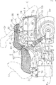
Der unter dem hinteren Sitz Sr angeordnete Aufbewahrungskasten B der Vorrichtung besitzt in seinem vorderen Abschnitt den vorderen Aufbewahrungsbereich Af zum Unterbringen eines Helms H1 in vertikal orientierter Stellung und in seinem hinteren Abschnitt einen hinteren Aufbewahrungsbereich Ar zum Unterbringen eines anderen Helms H2 schräg hinter dem ersten Helm H1 in querverkippter Stellung.The storage box B of the apparatus disposed under the rear seat Sr has in its front portion the front storage area Af for housing a helmet H 1 in vertically oriented position and in its rear portion a rear storage area Ar for housing another helmet H 2 obliquely behind the first Helmet H 1 in Querverkippter position.

Bevorzugte Ausführungen sind in den Unteransprüchen angegeben.Preferred embodiments are specified in the subclaims.

Bevorzugt umfasst der Sitz einen vorderen Sitz und einen hinteren Sitz, die in Längsrichtung tandemartig angeordnet sind, wobei der Aufnahmekasten für die Helme einen mit dem hinteren Sitz abgedeckten oberen Bereich aufweist. Wenn zwei Helme in dem Aufnahmekasten untergebracht sind, kann eine Zugangsöffnung des Aufnahmekastens durch den hinteren Sitz geschlossen werden, und die zwei Helme können in und aus dem Aufnahmekasten genommen werden, wenn der hintere Sitz geöffnet ist.Preferably, the seat comprises a front seat and a rear seat, which are arranged in tandem in the longitudinal direction, wherein the receiving box for the helmets has a covered with the rear seat upper portion. When two helmets are accommodated in the receiving box, an access opening of the receiving box can be closed by the rear seat, and the two helmets can be taken in and out of the receiving box when the rear seat is opened.

Die Erfindung wird nun in Ausführungsbeispielen anhand der beigefügten Zeichnungen erläutert. Es zeigen:The invention will now be explained in embodiments with reference to the accompanying drawings. Show it:

1 eine Teillängsschnittsseitenansicht eines Kraftrads in Motorrollerbauart mit einer Helmaufnahmevorrichtung; 1 a partial longitudinal sectional side view of a motor scooter motorcycle with a helmet-receiving device;

2 eine Draufsicht auf das Kraftrad mit der Helmaufnahmevorrichtung, wobei die Kraftradrumpfabdeckung und ein Sitz weggelassen sind; 2 a plan view of the motorcycle with the helmet-receiving device, the Kraftradrumpfabdeckung and a seat are omitted;

3 eine vergrößerte Teillängsschnittsseitenansicht eines hinteren Abschnitts des Kraftrads mit der Helmaufnahmevorrichtung; 3 an enlarged partial longitudinal sectional side view of a rear portion of the motorcycle with the helmet receiving device;

4 eine Längsschnittsansicht entlang Linie 4-4 von 2; und 4 a longitudinal sectional view taken along line 4-4 of 2 ; and

5 eine Querschnittsansicht entlang Linie 5-5 von 2. 5 a cross-sectional view taken along line 5-5 of 2 ,

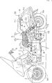
Eine Ausführung der Erfindung bei einem Kraftrad in Motorrollerbauart wird nachfolgend anhand der 1 bis 5 beschrieben.An embodiment of the invention in a motorcycle in scooter type will be described below with reference to 1 to 5 described.

Die Begriffe ”oben” und ”unten”, ”links” und ”rechts” und ”vorne” und ”hinten” verstehen sich in bezug auf die Fahrtrichtung des Kraftrads.The terms "up" and "down", "left" and "right" and "front" and "rear" are in relation to the direction of travel of the motorcycle.

Gemäß den 1 und 2 umfasst eine Hauptrahmenanordnung F, die als Rahmen des Kraftrads dient, einen Frontrahmen Ff, eine Motoreinheit Eu zum Antrieb des Kraftrads sowie einen Heckrahmen Fr, die integral miteinander verbunden sind. Der Frontrahmen Ff umfaßt ein Kopfrohr 1 und ein gegabeltes Hauptrohr 2, das sich von dort in Richtung nach hinten und unten integral erstreckt. Das Hauptrohr 2 umfaßt ein Rohr mit rechteckigem Querschnitt. An dem Kopfrohr 1 ist eine Frontgabel 3 lenkbar gelagert, an deren Unterende durch eine Welle ein Vorderrad Wf gelagert ist. Am Oberende der Frontgabel 3 ist ein Lenkergriff 4 befestigt. Ein oberer Abschnitt der Motoreinheit Eu ist am Unterende des Hauptrohrs 2 und am Unterende eines Stützrahmens 5, der sich von dem Hauptrohr 2 nach unten erstreckt, durch eine Mehrzahl von Verbindungsbolzen 6 befestigt. Die Motoreinheit Eu besitzt einen vorderen Abschnitt, der an dem Frontrahmen Ff aufgehängt ist. Die Motoreinheit Eu umfasst an ihrem vorderen Abschnitt einen liegenden Boxermotor 7. Der Motor 7 besitzt ein Paar von Zylindern 7 1, die im wesentlichen horizontal in Richtung nach links und rechts auswärts abstehen, sowie eine in Längsrichtung erstreckende Kurbelwelle. Die Motoreinheit Eu besitzt ferner an ihrem hinteren Abschnitt ein Getriebegehäuse 8, das an dem Heckrahmen Fr aufgehängt ist.According to the 1 and 2 comprises a main frame assembly F, which serves as the frame of the motorcycle, a front frame Ff, a motor unit Eu for driving the motorcycle and a rear frame Fr, which are integrally connected to each other. The front frame Ff comprises a head pipe 1 and a forked main pipe 2 moving from there towards extends integrally back and down. The main pipe 2 comprises a tube of rectangular cross-section. At the head pipe 1 is a front fork 3 mounted steerable, at the lower end by a shaft, a front wheel Wf is mounted. At the top of the front fork 3 is a handlebar grip 4 attached. An upper portion of the motor unit Eu is at the lower end of the main pipe 2 and at the bottom of a support frame 5 that is different from the main pipe 2 extends down through a plurality of connecting bolts 6 attached. The motor unit Eu has a front portion suspended on the front frame Ff. The motor unit Eu comprises at its front portion a lying boxer engine 7 , The motor 7 owns a pair of cylinders 7 1 , which protrude substantially horizontally in the direction of left and right outward, and a longitudinally extending crankshaft. The motor unit Eu further has a gear housing at its rear portion 8th , which is hung on the rear frame Fr.

Der Heckrahmen Fr hat die Form eines nach oben und unten offenen Rahmens, mit einem Heckrohr 10, einer über dem Heckrohr 10 angeordneten Sitzschiene 11 und einer Mehrzahl von Verbindungsrohren 12, die integral das Heckrohr 10 mit der Sitzschiene 11 verbinden. Ein Aufnahmekasten B zur Aufnahme zweier Helme H1, H2 ist in dem Heckrahmen Fr angeordnet. Ein Vorderende des Heckrohrs 10 ist integral mit dem Hinterende der Motoreinheit Eu, d. h. entgegengesetzten Enden eines Hinterendes des Getriebegehäuses 8, durch Verbindungsbolzen 13 verbunden und erstreckt sich aufwärts in Richtung nach hinten. Linke und rechte Seitenrohre 10 1 sind lösbar mit dem Hinterende des Heckrohrs 10 gekoppelt. Hinterenden der linken und rechten Seitenrohre 10 1 sind durch ein Endrohr 10 2 miteinander verbunden. Wie in den 2 und 3 gezeigt, erstreckt sich die Sitzschiene 11 über dem Heckrohr 10 im wesentlichen parallel hierzu nach hinten und ist, in Draufsicht gesehen, U-förmig mit geschlossenem Hinterende. Vordere linke und rechte Enden der Sitzschiene 11 sind integral mit linken und rechten Oberseiten der Motoreinheit Eu durch Verbindungsbolzen 14 verbunden. Das Heckrohr 10 und die Sitzschiene 11 sind durch eine Mehrzahl von Verbindungsrohren 12 integral miteinander verbunden. Zwei Laschen 15 stehen mit seitlichem Abstand voneinander integral von dem Endrohr 10 2 hoch. Oberenden der Laschen 15 sind lösbar mit dem Hinterende der Sitzschiene 11 verbunden. Die linken und rechten Seitenrohre 10 1, das Endrohr 10 2 und die Laschen 15 sind integral miteinander und lösbar an den Hinterenden des Heckrohrs 10 und der Sitzschiene 11 angebracht, um den Aufnahmekasten B leicht in dem Heckrahmen Fr anbringen zu können.The rear frame Fr has the form of an upwardly and downwardly open frame, with a tail pipe 10 one above the tail boom 10 arranged seat rail 11 and a plurality of connecting pipes 12 that integrally the tail pipe 10 with the seat rail 11 connect. A receiving box B for receiving two helmets H 1 , H 2 is arranged in the rear frame Fr. A front end of the tail pipe 10 is integral with the rear end of the motor unit Eu, that is, opposite ends of a rear end of the transmission case 8th , by connecting bolts 13 connected and extends upward in the backward direction. Left and right side pipes 10 1 are detachable with the rear end of the tail pipe 10 coupled. Rear ends of the left and right side tubes 10 1 are through a tailpipe 10 2 interconnected. As in the 2 and 3 shown, the seat rail extends 11 over the tail pipe 10 substantially parallel thereto to the rear and is, seen in plan view, U-shaped with closed rear end. Front left and right ends of the seat rail 11 are integral with left and right upper sides of the motor unit Eu by connecting bolts 14 connected. The tail pipe 10 and the seat rail 11 are through a plurality of connecting pipes 12 integrally connected with each other. Two tabs 15 stand with lateral distance from each other integrally from the tailpipe 10 2 high. Upper ends of the flaps 15 are detachable with the rear end of the seat rail 11 connected. The left and right side tubes 10 1 , the tailpipe 10 2 and the tabs 15 are integral with each other and detachable at the rear ends of the tail tube 10 and the seat rail 11 mounted to easily mount the receiving box B in the rear frame Fr.

Wie in 1 gezeigt, ist ein Großteil der Hauptrahmenanordnung F mit Frontrahmen Fr, Motoreinheit Eu und Heckrahmen Fr von einer Rumpfabdeckung C abgedeckt.As in 1 shown, a majority of the main frame assembly F with front frame Fr, engine unit Eu and rear frame Fr is covered by a hull cover C.

Wie in den 1 bis 3 gezeigt, ist ein Schwenkarm 18 vertikal schwenkbar an einem unteren Abschnitt des Hinterendes der Motoreinheit Eu durch eine Schwenkwelle 19 gelagert. Am Hinterende des Schwenkarms 18 ist durch eine Welle ein Hinterrad Wr drehbar gelagert. Ein hinterer Dämpfer 20 ist zwischen dem Schwenkarm 18 und dem Heckrahmen Fr angeschlossen. Der Schwenkarm 18 enthält einen an sich bekannten Kraftübertragungsmechanismus (nicht gezeigt) zur Antriebskraftübertragung von der Motoreinheit Eu auf das Hinterrad Wr. Ein seitlich vorstehender Fußaufsetzrahmen 9 ist an einem unteren Abschnitt der Motoreinheit Eu befestigt.As in the 1 to 3 shown is a swivel arm 18 vertically pivotable at a lower portion of the rear end of the motor unit Eu by a pivot shaft 19 stored. At the rear end of the swivel arm 18 is rotatably supported by a shaft, a rear wheel Wr. A rear damper 20 is between the swivel arm 18 and the rear frame Fr is connected. The swivel arm 18 includes a per se known power transmission mechanism (not shown) for driving power transmission from the motor unit Eu to the rear wheel Wr. A laterally protruding Fußaufsetzrahmen 9 is attached to a lower portion of the motor unit Eu.

Der Heckrahmen Fr bildet über und unter sich, über dem Hinterrad Wr, einen offenen Raum. Der Raum enthält den Aufnahmekasten B dieser Ausführung.The rear frame Fr forms above and below, above the rear wheel Wr, an open space. The room contains the receiving box B of this embodiment.

Strukturelle Details des Aufnahmekastens B werden nun anhand der 1 bis 3 sowie der 4 und 5 beschrieben. Der Aufnahmekasten B ist aus Metallplatten oder Kunststoffplatten hergestellt und umfaßt einen nach oben offenen unteren Kasten Bl und einen nach oben und unten offenen oberen Kasten Bu, der integral mit dem Oberrand der Öffnung des unteren Kastens Bl verbunden ist. Der untere Kasten Bl besitzt einen Verbindungsflansch, der vom Oberrand seiner Öffnung nach außen absteht, und der obere Kasten Bu besitzt einen Verbindungsflansch, der vom Unterrand seiner Öffnung nach außen absteht. Diese Verbindungsflansche sind integral miteinander entlang einer Verbindungslinie I-I verbunden, die sich im wesentlichen in Längsrichtung horizontal erstreckt, wie in 3 gezeigt. Der Aufnahmekasten B ist an dem Heckrahmen Fr durch eine Mehrzahl von Verbindungsbolzen 22 lösbar befestigt.Structural details of the receiving box B will now be described with reference to FIG 1 to 3 as well as the 4 and 5 described. The receiving box B is made of metal plates or plastic plates and includes an upper open bottom box Bl and an upper and lower open upper box Bu, which is integrally connected to the upper edge of the opening of the lower box Bl. The lower box B1 has a connecting flange projecting outwardly from the upper edge of its opening, and the upper box Bu has a connecting flange projecting outwardly from the lower edge of its opening. These connecting flanges are integrally connected together along a connecting line II extending horizontally in a substantially longitudinal direction, as in FIG 3 shown. The receiving box B is at the rear frame Fr by a plurality of connecting bolts 22 releasably secured.

Der Aufnahmekasten B ist in dem Heckrahmen Fr aufgenommen, und ist lang genug zur Aufnahme Zweier Helme H1, H2 in längsüberlappender Beziehung an längs beabstandeten Stellen, und eine Querbreite, die kleiner als die Breite des Kraftrads ist. Der Aufnahmekasten B ist kastenförmig, wobei seine Querbreite an seinem hinteren Abschnitt größer ist als an seinem vorderen Abschnitt, und umfaßt eine flache Vorderwand 23, linke und rechte Seitenwände 24, 25, die im wesentlichen rechtwinklig von den jeweiligen linken und rechten Rändern der Vorderwand 23 nach hinten abstehen, eine hintere Wand 26, die glatt kontinuierlich mit den Hinterrändern der linken und rechten Seitenwände 24, 25 verbunden ist und als nach hinten konvexer Dom ausgebildet ist, sowie eine Bodenwand 27, die eine untere Öffnung schließt, die von der Vorderwand 23, den linken und rechten Seitenwänden 24, 25 und der hinteren Wand 26 umgeben ist. Der Aufnahmekasten B besitzt in seinem oberen Bereich eine Zugangsöffnung. Der Aufnahmekasten B besitzt einen vorderen Aufnahmebereich Af, der in seinem vorderen Bereich definiert ist zur Aufnahme des vorderen Helms H1 in vertikal aufrechter Orientierung, sowie einen hinteren Aufnahmebereich Ar, der in seinem hinteren Abschnitt definiert ist zur Aufnahme eines hinteren Helms H2 in seitlich gekippter Orientierung schräg hinter dem Helm H1, wobei der vordere und hintere Speicherbereich Af und Ar kontinuierlich durchgehend ausgebildet sind. Die Querbreite des hinteren Aufnahmebereichs Ar ist größer als die Querbreite des vorderen Aufnahmebereichs Af.The receiving box B is received in the rear frame Fr, and is long enough to receive twin helmets H 1 , H 2 in longitudinal overlapping relationship at longitudinally spaced locations, and a transverse width that is smaller than the width of the motorcycle. The receiving box B is box-shaped, with its transverse width at its rear portion is greater than at its front portion, and includes a flat front wall 23 , left and right side walls 24 . 25 which are substantially perpendicular to the respective left and right edges of the front wall 23 projecting to the rear, a rear wall 26 that are smoothly continuous with the trailing edges of the left and right sidewalls 24 . 25 is connected and is designed as a convex dome to the rear, and a bottom wall 27 which closes a lower opening, that of the front wall 23 , the left and right side walls 24 . 25 and the back wall 26 is surrounded. The receiving box B has an access opening in its upper area. The receiving box B has a front receiving portion Af which is defined in its front portion for receiving the front helmet H 1 in vertically upright orientation, and a rear receiving portion Ar defined in its rear portion for receiving a rear helmet H 2 laterally tilted orientation obliquely behind the helmet H 1 , wherein the front and rear storage area Af and Ar are continuously formed continuously. The transverse width of the rear receiving area Ar is larger than the transverse width of the front receiving area Af.

Wie klar aus den 4 und 5 zu entnehmen, erstreckt sich ein Radhaus 30, das einer Oberseite des Hinterrads Wr gegenüberliegt, an der Bodenwand 27 des Aufnahmekastens B über die vorderen und hinteren Aufnahmebereiche Af, Ar hinweg. Das Radhaus 30 ist in einem quermittigen Abschnitt der Bodenwand 27 bogenförmig ausgebildet und erstreckt sich im wesentlichen über die volle Längslänge der Bodenwand 27 zu dem Aufnahmekasten B hin. Das Radhaus 30 ermöglicht, daß eine bogenförmige mittige Bodenwand 27c, die sich als Vertiefung in den quermittigen Abschnitt des Aufnahmekastens B erstreckt, und linke und rechte Bodenwände 27l, 27r, die seitlich der bogenförmigen mittleren Bodenwand 27c und tiefer als die bogenförmige mittlere Bodenwand 27c angeordnet ist, in dem Aufnahmekasten B ausgebildet werden können. Der nach außen konvexe Dom der hinteren Wand 26 ist im wesentlichen komplementär zur Oberseite des hinteren Helms H2 ausgebildet und paßt über die Oberseite des hinteren Helms H2, der in dem hinteren Abschnitt des Aufnahmekastens B aufgenommen ist, um hierdurch den hinteren Helm H2 stabil zu stützen.How clear from the 4 and 5 to take a wheelhouse extends 30 that faces an upper side of the rear wheel Wr, on the bottom wall 27 of the receiving box B over the front and rear receiving areas Af, Ar away. The wheelhouse 30 is in a mid-section of the bottom wall 27 arcuate and extends substantially over the full longitudinal length of the bottom wall 27 to the receiving box B out. The wheelhouse 30 allows an arcuate central bottom wall 27c , which extends as a recess in the transverse center portion of the receiving box B, and left and right bottom walls 27l . 27r , the side of the arcuate middle bottom wall 27c and deeper than the arcuate middle bottom wall 27c is arranged, can be formed in the receiving box B. The outwardly convex dome of the back wall 26 is formed substantially complementary to the top of the rear helmet H 2 and fits over the top of the rear helmet H 2 , which is received in the rear portion of the receiving box B, thereby stably supporting the rear helmet H 2 .

Die in dem oberen Bereich des Aufnahmekastens B ausgebildete Zugangsöffnung 28 ist von der Fläche her kleiner als die Querschnittsfläche seines mittleren Abschnitts.The access opening formed in the upper portion of the receiving box B. 28 is smaller in area than the cross-sectional area of its middle section.

Wie klar aus den 4 und 5 ersichtlich, wird der vordere Helm, hier ein Integralhelm mit voller Gesichtsabdeckung H1, durch die Zugangsöffnung 28 in den vorderen Aufnahmebereich Af des Aufnahmekastens B eingesetzt und wird darin in vertikal aufrechter Orientierung untergebracht. Der Helm H1 sitzt mit seinem unteren Öffnungsrand entlang der bogenförmigen mittleren Bodenwand 27c der Bodenwand 27 ohne jeden Spalt dazwischen auf. Der hintere Helm, hier ein sogenannter Jet-Helm H2 ohne vollflächige Gesichtsabdeckung, ist in dem hinteren Aufnahmebereich Ar des Aufnahmekastens B in einer seitlich oder quer gekippten Orientierung schräg hinter dem vorderen Helm H1 untergebracht. Der untere Abschnitt des hinteren Helms H2 fällt in den tieferen linken Aufnahmebereich, wobei die bogenförmige mittlere Bodenwand 27c teilweise in die Öffnung des hinteren Helms H2 ragt, um hierdurch die Höhe des so untergebrachten hinteren Helms H2 zu reduzieren. Wie in 4 gezeigt, bei der zwei Helme H1, H2 in dem Aufnahmekasten B untergebracht sind, überlappen diese zwei Helme H1, H2 einander in der Längsrichtung, so dass die Längslänge der untergebrachten Helme H1, H2 reduziert werden kann.How clear from the 4 and 5 As can be seen, the front helmet, here an integral helmet with full face H 1 , through the access opening 28 is inserted into the front receiving area Af of the receiving box B and is accommodated therein in a vertically upright orientation. The helmet H 1 sits with its lower edge of the opening along the arcuate middle bottom wall 27c the bottom wall 27 without any gap in between. The rear helmet, here a so-called jet helmet H 2 without full face cover, is housed in the rear receiving area Ar of the receiving box B in a laterally or transversely tilted orientation obliquely behind the front helmet H 1 . The lower portion of the rear helmet H 2 falls into the lower left receiving area, with the arcuate middle bottom wall 27c partially protrudes into the opening of the rear helmet H 2 , to thereby reduce the height of the thus accommodated rear helmet H 2 . As in 4 shown, in which two helmets H 1 , H 2 are accommodated in the receiving box B, these two helmets H 1 , H 2 overlap each other in the longitudinal direction, so that the longitudinal length of the accommodated helmets H 1 , H 2 can be reduced.

Ein Sitz S für darauf sitzende Personen ist an der Sitzschiene 11 des Heckrahmens Fr öffen- und schließbar angebracht. Der Sitz S umfaßt einen vorderen Sitz Sf für einen Fahrer und einen hinteren Sitz Sr für einen Beifahrer oder Passagier, die in Längsrichtung voneinander getrennt sind. Diese vorderen und hinteren Sitze Sf, Sr sind in Längsrichtung tandemartig entlang der Längsachse des Rumpfrahmens F angeordnet. Der vordere Sitz Sf ist unmittelbar vor dem Aufnahmekasten B angeordnet, und der hintere Sitz Sr ist unmittelbar über dem Aufnahmekasten B angeordnet. Wenn der hintere Sitz Sr geschlossen oder niedergedrückt wird, schließt er die Zugangsöffnung 28.A seat S for people sitting on it is on the seat rail 11 of the rear frame Fr openable and closable. The seat S includes a front seat Sf for a driver and a rear seat Sr for a passenger or passenger, which are separated from each other in the longitudinal direction. These front and rear seats Sf, Sr are arranged longitudinally in tandem along the longitudinal axis of the fuselage frame F. The front seat Sf is disposed immediately in front of the receiving box B, and the rear seat Sr is disposed immediately above the receiving box B. When the rear seat Sr is closed or depressed, it closes the access opening 28 ,

Das vordere Unterende des vorderen Sitzes Sf ist mit der Sitzschiene 11 durch einen Schwenkzapfen 32 verbunden und kann daher um den Schwenkzapfen 32 herum nach hinten geöffnet und geschlossen werden. Der vordere Sitz Sf trägt an seinem hinteren Unterende ein Sperrelement 33 zum lösbaren Sperreingriff mit einer vorderen Sperrvorrichtung Lf mit Schließzylinder an der Sitzschiene 11. Wenn der vordere Sitz Sf niedergedrückt wird, greift das Sperrelement 33 automatisch in die vordere Sperrvorrichtung Lf ein. Das hintere Unterende des hinteren Sitzes Sr ist durch einen Lenkermechanismus Li mit der Sitzschiene 11 verbunden. Der Lenkermechanismus Li umfaßt einen ersten Lenker 36 und einen zweiten Lenker 37, der hinter dem ersten Lenker 36 angeordnet ist und ein wenig kürzer ist als der erste Lenker 36. Die ersten und zweiten Lenker 36, 37 sind im wesentlichen parallel zueinander, und ihre Unterenden sind durch Zapfen mit der Sitzschiene 11 verbunden, und ihre Oberenden sind mit den hinteren Unterenden des hinteren Sitzes Sr durch Zapfen verbunden. Der hintere Sitz Sr kann mittels des Lenkermechanismus Li nach vorne geöffnet und geschlossen werden. Wenn der hintere Sitz Sr geöffnet wird, bewegt er sich leicht nach vorne, wie in 3 mit den strichpunktierten Linien dargestellt, so daß der hintere Sitz Sr ohne Störung mit einem an der Sitzschiene 11 angebrachten Griff 38 geöffnet werden kann. Wie in 3 gezeigt, besitzt die vordere Wand 23 des Aufnahmekastens B einen Oberrand, der sich zu einer Stelle in der Nähe des hinteren Endes des vorderen Sitzes Sf erstreckt. Der hintere Sitz Sr, der die Zugangsöffnung 28 des Aufnahmekastens B verschließt, besitzt einen Vorderrand, der in überlagerter Beziehung zum Hinterrand des vorderen Sitzes Sf angeordnet ist. Der hintere Sitz Sr kann geöffnet und geschlossen werden, während der vordere Sitz Sf geschlossen bleibt, um die Helme H1, H2 oder andere Gegenstände in den Aufnahmekasten B zu setzen oder daraus zu entnehmen. Wie in 4 gezeigt, besitzt der hintere Sitz Sr eine Bodenplatte 40, in der eine durchgehende sphärische Ausnehmung 40 1 definiert ist, die sich von der Vorderwand 23 des Aufnahmekastens B zu einer Sitzposition des hinteren Sitzes Sr hin erstreckt. Die sphärische Ausnehmung 40 1 paßt auf die Oberseite des vorderen Helms H1 in dem Aufnahmekasten B und kann den vorderen Helm H1 halten, damit dieser nicht wackelt, wenn der hintere Sitz Sr geschlossen ist.The front lower end of the front seat Sf is with the seat rail 11 through a pivot 32 connected and therefore can around the pivot pin 32 to be opened and closed around backwards. The front seat Sf carries at its rear lower end a blocking element 33 for detachable locking engagement with a front locking device Lf with lock cylinder on the seat rail 11 , When the front seat Sf is depressed, the locking element engages 33 automatically into the front locking device Lf. The rear lower end of the rear seat Sr is connected to the seat rail by a link mechanism Li 11 connected. The link mechanism Li includes a first link 36 and a second handlebar 37 behind the first handlebar 36 is arranged and is a little shorter than the first handlebar 36 , The first and second handlebars 36 . 37 are substantially parallel to each other, and their lower ends are by pins with the seat rail 11 connected, and their upper ends are connected to the rear lower ends of the rear seat Sr by pins. The rear seat Sr can be opened and closed forward by means of the link mechanism Li. When the rear seat Sr is opened, it moves slightly forward as in 3 represented by the dotted lines, so that the rear seat Sr without interference with a on the seat rail 11 attached handle 38 can be opened. As in 3 shown has the front wall 23 of the receiving box B has an upper edge extending to a position near the rear end of the front seat Sf. The rear seat Sr, which is the access opening 28 of the receiving box B has a leading edge disposed in superimposed relation to the rear edge of the front seat Sf. The rear seat Sr can be opened and closed while the front seat Sf remains closed to seat or remove the helmets H 1 , H 2 or other objects in the accommodation box B. As in 4 shown, the rear seat Sr has a bottom plate 40 in which a continuous spherical recess 40 1 is defined, extending from the front wall 23 of the receiving box B to a seated position of the rear seat Sr. The spherical recess 40 1 fits on the top of the front helmet H 1 in the receiving box B and can hold the front helmet H 1 so that it does not wobble when the rear seat Sr is closed.

Der hintere Sitz Sr trägt an seinem vorderen Unterende ein Sperrelement 41 zum lösbaren Sperreingriff mit einer hinteren Sperrvorrichtung Lr mit Schließzylinder an der Sitzschiene 11. Wenn der hintere Sitz Sr niedergedrückt wird, greift das Sperrelement 41 automatisch in die hintere Sperrvorrichtung Lr ein.The rear seat Sr carries at its front lower end a blocking element 41 for detachable locking engagement with a rear locking device Lr with lock cylinder on the seat rail 11 , When the rear seat Sr is depressed, the locking element engages 41 automatically into the rear locking device Lr.

Die vorderen und hinteren Sperrvorrichtungen Lf, Lr und die Sperrelemente 33, 41 sind herkömmlicher Bauart und werden im Detail nicht näher erläutert.The front and rear locking devices Lf, Lr and the locking elements 33 . 41 are conventional design and are not explained in detail.

Wie in 3 gezeigt, ist ein Kraftstofftank Tf aus Kunstharz zur Kraftstoffversorgung der Motoreinheit Eu unter dem Vordersitz Sf angeordnet. Der Kraftstofftank Tf besitzt einen vorderen Abschnitt, der sich zu einer Stelle über dem Getriebegehäuse 8 der Motoreinheit Eu erstreckt und dort durch eine Lasche 42 befestigt ist, sowie einen hinteren Abschnitt, der an dem Heckrahmen Fr durch eine Lasche 43 befestigt ist. Wie in 5 gezeigt, ist ein eine Batterie enthaltender Batteriekasten Bb an einer linken Seite des Aufnahmekastens B befestigt. Der Griff 38, der den hinteren Abschnitt des hinteren Sitzes Sr umgibt, ist an der Sitzschiene 11 befestigt.As in 3 is shown, a fuel tank Tf made of synthetic resin for supplying fuel to the motor unit Eu is arranged under the front seat Sf. The fuel tank Tf has a front portion that extends to a position above the transmission housing 8th the motor unit Eu extends and there by a tab 42 is fastened, as well as a rear section, which at the rear frame Fr through a flap 43 is attached. As in 5 1, a battery box Bb including a battery is attached to a left side of the receiving box B. As shown in FIG. The handle 38 that surrounds the rear portion of the rear seat Sr is on the seat rail 11 attached.

Nachfolgend wird der Betrieb dieser Ausführung erläutert.The operation of this embodiment will be explained below.

Bei geöffnetem hinteren Sitz Sr werden die zwei Helme H1, H2 durch die Zugangsöffnung 28 in den Aufbewahrungskasten B gelegt. Insbesondere, wie in den 4 und 5 gezeigt, wird der Helm H1, hier der Integralhelm, in quermittiger Position in dem vorderen Aufbewahrungsbereich Hf des Aufbewahrungskastens B in vertikal aufrechter Orientierung untergebracht. Der Helm H1 sitzt mit seinem unteren Öffnungsrand in passend auf der bogenförmigen mittleren Bodenwand 27c auf, die das Radhaus 30 definiert, und seine Vorderseite liegt an der Innenfläche der Vorderwand 23 an. Der andere Helm H2, hier der Jet-Helm, wird in einem linken Bereich des hinteren Aufbewahrungsbereichs Ar des Aufbewahrungskastens B in einer querverkippten Orientierung schräg hinter dem vorderen Helm H1 untergebracht. Der Helm H2 lehnt sich gegen die linke Seitenwand 24 an, wobei die gekrümmte mittlere Bodenwand 27c teilweise in den Helm H2 hineinragt. Die Außenfläche des Helms H2 liegt passend an der Innenfläche des hinteren Wand 26 an. Obwohl das Radhaus 30 in den Aufbewahrungskasten B eingeformt ist und in diesen ragt, kann auf diese Weise der hintere Helm H2 untergebracht werden, ohne sich mit dem Radhaus 30 zu stören. Wie in 3 gezeigt, überlappen hintere und vordere Abschnitte des vorderen und hinteren Helms H1, H2 einander, so dass die Längslänge des Aufbewahrungskastens B um die Überlappungslänge der vorderen und hinteren Helme H1, H2 reduziert werden kann. Die Aufbewahrungshöhe des hinteren Helms H2 kann reduziert werden, weil der hintere Helm H2 schräg hinter dem vorderen Helm H1 quer verkippt ist.When the rear seat Sr is open, the two helmets H 1 , H 2 pass through the access opening 28 placed in the storage box B. In particular, as in the 4 and 5 The helmet H 1 , in this case the full-face helmet, is accommodated in the mid-position in the front storage area Hf of the storage box B in a vertically upright orientation. The helmet H 1 sits with its lower opening edge in fitting on the arcuate middle bottom wall 27c on that the wheelhouse 30 defined, and its front lies on the inner surface of the front wall 23 at. The other helmet H 2 , here the jet helmet, is accommodated in a left portion of the rear storage area Ar of the storage box B in a transverse tilted orientation obliquely behind the front helmet H 1 . The helmet H 2 leans against the left side wall 24 on, with the curved middle bottom wall 27c partially protruding into the helmet H 2 . The outer surface of the helmet H 2 fits the inner surface of the rear wall 26 at. Although the wheelhouse 30 is formed in the storage box B and protrudes into this, the rear helmet H 2 can be accommodated in this way without interfering with the wheel arch 30 disturb. As in 3 9, rear and front portions of the front and rear helmets H 1 , H 2 overlap one another, so that the longitudinal length of the storage box B can be reduced by the overlap length of the front and rear helmets H 1 , H 2 . The storage height of the rear helmet H 2 can be reduced because the rear helmet H 2 is tilted transversely obliquely behind the front helmet H 1 .

Nachdem die zwei Helme H1, H2 in dem Aufbewahrungskasten B untergebracht wurden, wird der hintere Sitz Sr geschlossen. Die Bodenplatte 40 mit der Vertiefung 40 1 kann den vorderen Helm H1 positioniert halten, so dass dieser nicht wackelt.After the two helmets H 1 , H 2 have been accommodated in the storage box B, the rear seat Sr is closed. The bottom plate 40 with the recess 40 1 can keep the front helmet H 1 positioned so that it does not wobble.

Das Radhaus 30 ist an der Bodenwand 27 des Aufbewahrungskastens B ausgebildet und ragt als Vertiefung in den Aufbewahrungskasten B hinein. Das Radhaus 30 ermöglicht, dass der Aufbewahrungskasten B näher am Hinterrad Br angeordnet wird, so dass die Höhe des Aufbewahrungskastens B vom Boden reduziert werden kann.The wheelhouse 30 is on the bottom wall 27 of the storage box B and protrudes into the storage box B as a recess. The wheelhouse 30 allows the storage box B to be located closer to the rear wheel Br, so that the height of the storage box B can be reduced from the ground.

Obwohl im obigen Beispiel der Integralhelm und der Jet-Helm untergebracht werden, kann man in den Aufbewahrungskasten auch zwei Helme unabhängig von ihrer jeweiligen Bauart unterbringen. In der Ausführung sind der vordere und der hintere Sitz in Längsrichtung unterteilt. Jedoch kann der Sitz auch ein Tandemsitz sein, dessen vorderer und hinterer Sitzabschnitt integral miteinander verbunden sind.Although in the example above, the full face helmet and the jet helmet are housed, you can also put two helmets in the storage box, regardless of their design. In the embodiment, the front and rear seats are divided longitudinally. However, the seat may be a tandem seat whose front and rear seat portions are integrally connected with each other.

Claims (4)

Helmaufnahmevorrichtung in einem Kraftrad, die einen Aufbewahrungskasten (B) für Helme (H1, H2) unter einem Sitz (S) für einen darauf sitzenden Passagier aufweist, wobei der Aufbewahrungskasten (B) einen in seinem vorderen Abschnitt definierten vorderen Aufbewahrungsbereich (Af) zur Aufbewahrung eines Helms (H1) in vertikal orientierter Stellung sowie einen in seinem hinteren Abschnitt definierten hinteren Aufbewahrungsbereich (Ar) zur Aufbewahrung eines anderen Helms (H2) aufweist, dadurch gekennzeichnet, dass der andere Helm (H2) schräg hinter dem Helm (H1) in seitlich gekippter Stellung und diesen in Längsrichtung überlappend angeordnet ist.A helmet-holding device in a motorcycle having a storage box (B) for helmets (H1, H2) under a seat (S) for a passenger seated thereon, the storage box (B) having a front storage area (Af) defined in its front portion for storage a helmet (H1) in a vertically oriented position and a rear storage area (Ar) defined in its rear section for storing another helmet (H2), characterized in that the other helmet (H2) is inclined laterally behind the helmet (H1) tilted position and this is arranged overlapping in the longitudinal direction. Helmaufnahmevorrichtung nach Anspruch 1, dadurch gekennzeichnet, dass der Aufbewahrungskasten (B) einen oben offenen unteren Kasten (Bl) sowie einen oben und unten offenen oberen Kasten (Bu) aufweist, der integral mit einem Oberrand einer Öffnung des unteren Kastens (Bl) verbunden ist.Helmet receiving device according to claim 1, characterized in that the storage box (B) has an upper open lower box (Bl) and a top and bottom open top box (Bu), which is integrally connected to an upper edge of an opening of the lower box (Bl). Helmaufnahmevorrichtung nach Anspruch 1, dadurch gekennzeichnet, dass der vordere Aufbewahrungsbereich (Af) eine Querbreite hat, die kleiner ist als eine zweite Querbreite des hinteren Aufbewahrungsbereichs (Ar).A helmet accommodating apparatus according to claim 1, characterized in that the front storage area (Af) has a transverse width which is smaller than a second transverse width of the rear storage area (Ar). Helmaufnahmevorrichtung nach Anspruch 1, dadurch gekennzeichnet, dass die in dem oberen Bereich des Aufbewahrungskastens (B) ausgebildete Zugangsöffnung (28) von der Fläche her kleiner als die Querschnittsfläche des mittleren Abschnitts des Aufbewahrungskastens (B) ist.Helmet receiving device according to claim 1, characterized in that the access opening formed in the upper region of the storage box (B) (FIG. 28 ) is smaller in area than the cross-sectional area of the central portion of the storage box (B).
DE10011374A 1999-03-30 2000-03-09 Helmet cradle for a motorcycle Expired - Fee Related DE10011374B4 (en)

Applications Claiming Priority (2)

Application Number Priority Date Filing Date Title
JPP087540 1999-03-30
JP08754099A JP4394769B2 (en) 1999-03-30 1999-03-30 Motorcycle helmet storage device

Publications (2)

Publication Number Publication Date
DE10011374A1 DE10011374A1 (en) 2000-10-05
DE10011374B4 true DE10011374B4 (en) 2013-02-28

Family

ID=13917829

Family Applications (1)

Application Number Title Priority Date Filing Date
DE10011374A Expired - Fee Related DE10011374B4 (en) 1999-03-30 2000-03-09 Helmet cradle for a motorcycle

Country Status (4)

Country Link
US (1) US6336579B1 (en)
JP (1) JP4394769B2 (en)
DE (1) DE10011374B4 (en)
FR (1) FR2791621B1 (en)

Families Citing this family (25)

* Cited by examiner, † Cited by third party
Publication number Priority date Publication date Assignee Title
JP3879437B2 (en) * 2000-06-23 2007-02-14 スズキ株式会社 Motorcycle article storage device
JP3956594B2 (en) * 2000-08-31 2007-08-08 スズキ株式会社 Motorcycle article storage device
JP3831186B2 (en) * 2000-09-08 2006-10-11 本田技研工業株式会社 Motorcycle storage box structure
US20040079573A1 (en) * 2001-04-24 2004-04-29 Suzuki Motor Corporation Motorcycle and storage box arrangement thereof
EP1530536B1 (en) * 2002-07-31 2010-05-19 Honda Giken Kogyo Kabushiki Kaisha Four-wheeled vehicle
ITTO20020687A1 (en) * 2002-07-31 2004-02-01 Honda Motor Co Ltd ROOF CONTRACTILE VEHICLE
JP4173337B2 (en) * 2002-08-26 2008-10-29 本田技研工業株式会社 Wind guide device for motorcycle
US6749036B1 (en) * 2003-01-22 2004-06-15 Polaris Industries Inc. Snowmobile accessory attachment system and integrated snowmobile cargo rack
DE10323443A1 (en) * 2003-05-23 2004-12-09 Bayerische Motoren Werke Ag Luggage system for motorcycles, includes two side boxes which are mutually coupled with middle section and closed with single cover
US7556114B2 (en) * 2005-01-24 2009-07-07 Hanagan Michael W Motorcycle with interchangeable rear components
JP2007099098A (en) * 2005-10-05 2007-04-19 Honda Motor Co Ltd Motorcycle
US20070151789A1 (en) * 2005-12-08 2007-07-05 Polaris Industries Inc. Automatic motorcycle
JP2007210486A (en) * 2006-02-10 2007-08-23 Yamaha Motor Co Ltd Motorcycle
EP1864895B1 (en) 2006-06-09 2010-12-15 Yamaha Hatsudoki Kabushiki Kaisha Motorcycle
JP5072328B2 (en) * 2006-11-22 2012-11-14 本田技研工業株式会社 Motorcycle
JP2009107564A (en) * 2007-10-31 2009-05-21 Yamaha Motor Co Ltd Motorcycle
DE102008021981A1 (en) * 2008-05-02 2009-11-05 Bayerische Motoren Werke Aktiengesellschaft Two-wheeler, especially scooter or motorcycle
JP5310042B2 (en) * 2009-02-03 2013-10-09 スズキ株式会社 Motorcycle article storage structure
JP2010229840A (en) * 2009-03-26 2010-10-14 Honda Motor Co Ltd Motorcycle
DE102011078268B4 (en) 2011-06-29 2021-11-25 Bayerische Motoren Werke Aktiengesellschaft Two-wheeled vehicles, especially motorcycles or scooters
JP6018861B2 (en) * 2012-09-20 2016-11-02 本田技研工業株式会社 Saddle riding vehicle
EP2712791B1 (en) * 2012-09-28 2015-07-08 Yamaha Motor Co., Ltd. Straddle-type vehicle
US20190185091A1 (en) * 2017-12-15 2019-06-20 Dejan Mitrovic Multifunctional motorcycle passenger seat system
DE102021112196A1 (en) 2021-05-11 2022-11-17 Bayerische Motoren Werke Aktiengesellschaft Bench seat for a motor vehicle
DE102021120709A1 (en) 2021-08-10 2023-02-16 Bayerische Motoren Werke Aktiengesellschaft Seating arrangement for a tilting vehicle with an integrated storage compartment

Citations (11)

* Cited by examiner, † Cited by third party
Publication number Priority date Publication date Assignee Title
JPH0288376A (en) * 1988-09-27 1990-03-28 Honda Motor Co Ltd Helmet housing device for motorcycle
US4964438A (en) * 1989-10-02 1990-10-23 Ronald S. Welty Air duct plug
JPH0325089A (en) * 1989-06-22 1991-02-01 Yamaha Motor Co Ltd Motorcycle and motor tricycle
JPH04110287A (en) * 1990-08-31 1992-04-10 Suzuki Motor Corp Scooter type vehicle equipped with accommodation box
JPH04183690A (en) * 1990-11-16 1992-06-30 Honda Motor Co Ltd Article storing device for motor-bicycle
JPH04212686A (en) * 1990-12-07 1992-08-04 Suzuki Motor Corp Body of motor scooter
JPH04274981A (en) * 1991-02-28 1992-09-30 Suzuki Motor Corp Motor-bicycle/tricycle with receiving chamber
US5433286A (en) * 1988-09-27 1995-07-18 Honda Giken Kogyo Kabushiki Kaisha Motorcycle
JPH0872768A (en) * 1994-09-09 1996-03-19 Suzuki Motor Corp Scooter type vehicle provided with helmet storing chamber
JPH09323681A (en) * 1996-06-05 1997-12-16 Yamaha Motor Co Ltd Scooter type vehicle
JPH1067360A (en) * 1997-07-31 1998-03-10 Suzuki Motor Corp Scooter type vehicle

Family Cites Families (9)

* Cited by examiner, † Cited by third party
Publication number Priority date Publication date Assignee Title
JPS6181884A (en) * 1984-09-18 1986-04-25 本田技研工業株式会社 Scooter type minicar
US4726439A (en) * 1985-10-05 1988-02-23 Honda Giken Kogyo Kabushiki Kaisha Trunk structure in scooter-type vehicles
JPH0519275Y2 (en) * 1986-10-14 1993-05-20
US4964483A (en) * 1987-09-25 1990-10-23 Honda Giken Kogyo Kabushiki Kaisha Motor scooter
JP3675894B2 (en) * 1995-06-29 2005-07-27 ヤマハ発動機株式会社 Scooter-type motorcycle body frame
IT1285697B1 (en) * 1996-05-13 1998-06-18 Diego Sodo INTEGRATED HOLDER FOR MOTORCYCLES, SCOOTERS OR SIMILAR
JP3816210B2 (en) * 1997-09-30 2006-08-30 本田技研工業株式会社 Body structure of a low-floor motorcycle
JP4266245B2 (en) * 1998-05-29 2009-05-20 ヤマハ発動機株式会社 Motorcycle drive device
JP3956594B2 (en) * 2000-08-31 2007-08-08 スズキ株式会社 Motorcycle article storage device

Patent Citations (11)

* Cited by examiner, † Cited by third party
Publication number Priority date Publication date Assignee Title
JPH0288376A (en) * 1988-09-27 1990-03-28 Honda Motor Co Ltd Helmet housing device for motorcycle
US5433286A (en) * 1988-09-27 1995-07-18 Honda Giken Kogyo Kabushiki Kaisha Motorcycle
JPH0325089A (en) * 1989-06-22 1991-02-01 Yamaha Motor Co Ltd Motorcycle and motor tricycle
US4964438A (en) * 1989-10-02 1990-10-23 Ronald S. Welty Air duct plug
JPH04110287A (en) * 1990-08-31 1992-04-10 Suzuki Motor Corp Scooter type vehicle equipped with accommodation box
JPH04183690A (en) * 1990-11-16 1992-06-30 Honda Motor Co Ltd Article storing device for motor-bicycle
JPH04212686A (en) * 1990-12-07 1992-08-04 Suzuki Motor Corp Body of motor scooter
JPH04274981A (en) * 1991-02-28 1992-09-30 Suzuki Motor Corp Motor-bicycle/tricycle with receiving chamber
JPH0872768A (en) * 1994-09-09 1996-03-19 Suzuki Motor Corp Scooter type vehicle provided with helmet storing chamber
JPH09323681A (en) * 1996-06-05 1997-12-16 Yamaha Motor Co Ltd Scooter type vehicle
JPH1067360A (en) * 1997-07-31 1998-03-10 Suzuki Motor Corp Scooter type vehicle

Also Published As

Publication number Publication date
US6336579B1 (en) 2002-01-08
JP2000280950A (en) 2000-10-10
FR2791621B1 (en) 2004-06-18
JP4394769B2 (en) 2010-01-06
FR2791621A1 (en) 2000-10-06
DE10011374A1 (en) 2000-10-05

Similar Documents

Publication Publication Date Title
DE10011374B4 (en) Helmet cradle for a motorcycle
DE10016072B4 (en) Article storage device for a motorcycle
DE3301837C2 (en)
DE60300636T2 (en) Electrically powered vehicle
DE4101116C2 (en) Luggage box arrangement for a motorcycle
DE60123487T2 (en) Vehicle, in particular scooter-type vehicle
DE102004048479B4 (en) Luggage rack device for a motorcycle
DE102009004169B4 (en) Air filter structure of a small vehicle engine
DE102009010472B4 (en) Hull frame of a motorcycle
DE3824680C2 (en) motorcycle
DE102014214223B4 (en) Vehicle of the type in which you sit astride
DE3644645A1 (en) SCOOTER VEHICLE
DE10130098A1 (en) Luggage container unit for motorcycles esp. scooters has luggage box with upward facing inner projection above rear wheel to prevent small objects from moving within box
DE102015121515B4 (en) Inlet structure for a vehicle with a saddle
DE102006046005A1 (en) Saddle drive type vehicle e.g. motorcycle, housing structure, has housing at rear side of seat that includes front seat and rear seat, where housing is movably provided between upper side of rear seat and position at rear side of housing
DE2451859A1 (en) MOTORIZED TWO-WHEEL VEHICLE
DE60202920T2 (en) Scooter-like motorcycle
DE60102426T2 (en) Storage box on a two-wheeled motorcycle
DE102017130650A1 (en) SCHWINGE
DE3019648A1 (en) MOTORCYCLE
DE19951549C2 (en) Housing unit for a motorcycle
DE102020106588B4 (en) FASTENING STRUCTURE OF AN ELECTRICAL COMPONENT FOR A SADDLE SEAT VEHICLE
DE60018362T2 (en) Battery assembly for two-wheeler vehicle
DE69924663T2 (en) Scooter-like vehicle
DE10241689A1 (en) motorcycle

Legal Events

Date Code Title Description
OP8 Request for examination as to paragraph 44 patent law
R016 Response to examination communication
R018 Grant decision by examination section/examining division
R020 Patent grant now final

Effective date: 20130529

R119 Application deemed withdrawn, or ip right lapsed, due to non-payment of renewal fee

Effective date: 20141001