CN2867060Y - Locomotive air conditioner compressor fixing mechanism - Google Patents
Locomotive air conditioner compressor fixing mechanism Download PDFInfo
- Publication number
- CN2867060Y CN2867060Y CN 200520085240 CN200520085240U CN2867060Y CN 2867060 Y CN2867060 Y CN 2867060Y CN 200520085240 CN200520085240 CN 200520085240 CN 200520085240 U CN200520085240 U CN 200520085240U CN 2867060 Y CN2867060 Y CN 2867060Y
- Authority
- CN
- China
- Prior art keywords
- compressor
- fixing
- air conditioner
- locomotive air
- sides
- Prior art date
- Legal status (The legal status is an assumption and is not a legal conclusion. Google has not performed a legal analysis and makes no representation as to the accuracy of the status listed.)
- Expired - Fee Related
Links
Images

Landscapes
- Air-Conditioning For Vehicles (AREA)
- Compressor (AREA)
- Compressors, Vaccum Pumps And Other Relevant Systems (AREA)
Abstract
本实用新型所述机车空调的压缩机固定机构,而采取从压缩机底部两侧和顶部两侧的固定结构,沿压缩机卧式摆放的位置和制冷剂管路走向来实现多方位限位,从而最大限度的吸收震动能量、减少共振的幅度,保证压缩机内部结构在剧烈震荡的车况下保持稳定运行。所采用的固定方式是在压缩机的纵向方向上设置有两组固定支架,每固定支架均通过两侧的固定柱与机车空调的底板进行连接。卡箍环环绕在压缩机背部,而且卡箍环的两侧端部通过固定螺栓与底板进行连接。在卡箍环的内侧设置有数个缓冲胶垫,且在卡箍环外侧面设置有紧固螺栓,紧固螺栓贯穿卡箍环而将缓冲胶垫压紧在压缩机外侧。
The compressor fixing mechanism of the locomotive air conditioner described in the utility model adopts the fixing structure from both sides of the bottom and top sides of the compressor, and realizes multi-directional positioning along the horizontal position of the compressor and the direction of the refrigerant pipeline. , so as to absorb the vibration energy to the greatest extent, reduce the amplitude of resonance, and ensure that the internal structure of the compressor maintains stable operation under severe oscillating vehicle conditions. The fixing method adopted is that two groups of fixing brackets are arranged in the longitudinal direction of the compressor, and each fixing bracket is connected with the bottom plate of the locomotive air conditioner through fixing columns on both sides. The hoop ring surrounds the back of the compressor, and the ends on both sides of the hoop ring are connected to the bottom plate through fixing bolts. Several buffer rubber pads are arranged on the inner side of the clamp ring, and fastening bolts are arranged on the outer surface of the clamp ring, and the fastening bolts penetrate through the clamp ring to press the buffer rubber pads on the outside of the compressor.
Description
技术领域technical field
本实用新型涉及一种新型固定机构,该固定机构主要应用于机车空调的压缩机。The utility model relates to a novel fixing mechanism, which is mainly used in compressors of locomotive air conditioners.
背景技术Background technique
目前在火车、城市轻轨列车、旅行汽车和军用汽车,均普遍采用机车空调来调节车厢内的空气温度,以提供舒适的旅行环境。现有机车空调的内部系统器件均采用抗震固定结构,以应对机车高速运行、以及在颠簸的道路上行驶对空调器件所形成的冲击和破坏。At present, locomotive air conditioners are widely used in trains, urban light rail trains, station wagons and military vehicles to adjust the air temperature in the compartments to provide a comfortable travel environment. The internal system components of the existing locomotive air conditioner all adopt an anti-seismic fixed structure to cope with the impact and damage to the air conditioner components caused by the high-speed operation of the locomotive and the bumpy road.
如公开以下内容的在先专利,专利号是97208944,名称为空调器用减振装置,其方案是在旋转式压缩机的切线方向上安装吸振器,吸振器由弹簧和与弹簧相连的质量块组成。以解决配管与压缩机的联接处的疲劳断裂问题。将压缩机的大部分振动能量传递到吸振器上,降低压缩机这个振源的振动幅值,而吸振器的振动不会影响空调器的振动和噪声等性能。For example, the prior patent that discloses the following content, the patent number is 97208944, and the name is a vibration damping device for an air conditioner. The solution is to install a vibration absorber in the tangential direction of the rotary compressor. The vibration absorber is composed of a spring and a mass connected to the spring. . To solve the problem of fatigue fracture at the connection between the piping and the compressor. Most of the vibration energy of the compressor is transferred to the vibration absorber to reduce the vibration amplitude of the vibration source of the compressor, and the vibration of the vibration absorber will not affect the vibration and noise performance of the air conditioner.
以上现有压缩机减振装置并不适合于机车空调。由于其吸振器和弹簧相连的质量块并未对压缩机进行紧固,因而在高速运行和行驶在颠簸道路上时,压缩机本身剧烈震动而会引起内部结构的断裂和倾覆,由此会引发压缩机的损坏或是影响到系统管路内制冷剂的正常循环。同时,上述减振装置体积较大,也限制机车空调的小型化设计、不利于整机安装调试。Above existing compressor damping device is not suitable for locomotive air conditioner. Since the mass block connected by the shock absorber and the spring is not fastened to the compressor, when running at high speed or on a bumpy road, the compressor itself will vibrate violently and cause the internal structure to break and overturn, which will cause The damage of the compressor may affect the normal circulation of the refrigerant in the system pipeline. At the same time, the above-mentioned damping device has a large volume, which also limits the miniaturization design of the locomotive air conditioner, and is not conducive to the installation and commissioning of the whole machine.
实用新型内容Utility model content
本实用新型所述机车空调的压缩机固定机构,其设计目的在于解决上述问题和不足而采取底部两侧和顶部两侧的固定结构,沿压缩机卧式摆放的位置和制冷剂管路走向来实现多方位限位,从而最大限度的吸收震动能量、减少共振的幅度,保证压缩机内部结构在剧烈震荡的车况下保持稳定运行。The compressor fixing mechanism of the locomotive air conditioner described in the utility model is designed to solve the above problems and deficiencies by adopting fixed structures on both sides of the bottom and both sides of the top, along the position where the compressor is placed horizontally and the direction of the refrigerant pipeline. To achieve multi-directional limit, so as to absorb vibration energy to the greatest extent, reduce the amplitude of resonance, and ensure that the internal structure of the compressor maintains stable operation under severe oscillating vehicle conditions.
应用本实用新型所述压缩机固定机构的机车空调,采用卧置旋转式压缩机。The locomotive air conditioner using the compressor fixing mechanism of the utility model adopts a horizontal rotary compressor.
所采用的固定方式是在压缩机的纵向方向上设置有两组固定支架,每固定支架均通过两侧的固定柱与机车空调的底板进行连接。The fixing method adopted is that two groups of fixing brackets are arranged in the longitudinal direction of the compressor, and each fixing bracket is connected with the bottom plate of the locomotive air conditioner through fixing columns on both sides.
所述的固定支架从前后方向上,将压缩机固定在底板上。连接压缩机的进、出系统管件从固定支架上方穿过。The fixing bracket fixes the compressor on the base plate from front to back. The inlet and outlet system pipes connected to the compressor pass through above the fixing bracket.
为避免因机车高速运行或道路颠簸而对压缩机造成的震荡和破坏,本实用新型进一步的改进方案是,所述的固定结构还包括有数个卡箍环,卡箍环环绕在压缩机背部,而且卡箍环的两侧端部通过固定螺栓与底板进行连接。In order to avoid the shock and damage to the compressor caused by the high-speed running of the locomotive or the bumpy road, the further improvement of the utility model is that the fixed structure also includes several hoop rings, and the hoop rings surround the back of the compressor. Moreover, the ends on both sides of the hoop ring are connected with the bottom plate through fixing bolts.
压缩机壳体和卡箍环通常采用金属材质,为保证卡箍环与压缩机壳体连接紧密,能在机车高速运行或道路颠簸时卡箍环不会对压缩机造成过大的冲击,还可在卡箍环的内侧设置有数个缓冲胶垫,并且在卡箍环外侧面设置有紧固螺栓,紧固螺栓贯穿卡箍环而将缓冲胶垫压紧在压缩机壳体外侧。The compressor shell and hoop ring are usually made of metal. In order to ensure the tight connection between the hoop ring and the compressor shell, the hoop ring will not cause excessive impact on the compressor when the locomotive is running at high speed or the road is bumpy. Several buffer rubber pads can be arranged on the inner side of the clamp ring, and fastening bolts are arranged on the outer surface of the clamp ring, and the fastening bolts penetrate through the clamp ring to press the buffer rubber pads against the outside of the compressor housing.
如上所述,本实用新型机车空调的压缩机固定机构的优点是,压缩机采用卧式摆放占用空间小,在压缩机的底部和顶部两侧进行固定能够最大最大限度地吸收震动能量,保证压缩机与固定机构之间保持相对静止,从而有效地保证在剧烈震荡的车况下压缩机的正常工作运行。As mentioned above, the advantage of the compressor fixing mechanism of the locomotive air conditioner of the utility model is that the horizontal placement of the compressor takes up little space, and the fixing on both sides of the bottom and top of the compressor can absorb vibration energy to the maximum extent, ensuring The compressor and the fixing mechanism remain relatively static, thereby effectively ensuring the normal operation of the compressor under severe oscillating vehicle conditions.
附图说明Description of drawings
图1是所述压缩机与固定机构的侧视图;Fig. 1 is the side view of described compressor and fixing mechanism;
图2是所述压缩机与固定机构的俯视图;Fig. 2 is the top view of described compressor and fixing mechanism;
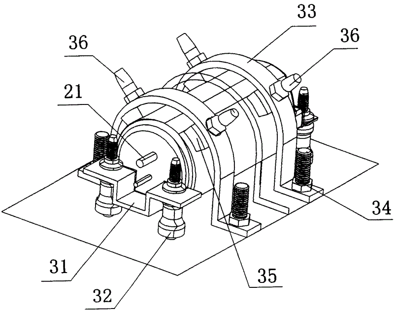
图3是所述压缩机与固定机构的斜视图。Fig. 3 is a perspective view of the compressor and the fixing mechanism.
如图1-图3所示,底板1,压缩机2,连接管件21,固定支架31,固定柱32,卡箍环33,固定螺栓34,缓冲胶垫35,紧固螺栓36。As shown in Figures 1-3, the
具体实施方式Detailed ways
实施例1,如图1至图3所示,应用所述机车空调的压缩机固定机构,在底板1的压缩机2采用卧置旋转式结构。
在压缩机2的纵向方向上设置有两组固定支架31,固定支架31通过两侧的固定柱32与底板1连接。Two sets of fixing brackets 31 are arranged in the longitudinal direction of the
连接压缩机2的进、出连接管件21从固定支架31上方穿过。The inlet and outlet connecting pipes 21 connected to the
2个卡箍环33环绕在压缩机2的背部,卡箍环33的两侧端部通过固定螺栓34与底板1连接。Two
在每一卡箍环33的内侧面设置有2个缓冲胶垫35,紧固螺栓36贯穿卡箍环33并将缓冲胶垫35压紧在压缩机2的壳体外侧。Two
Claims (3)
Priority Applications (1)
| Application Number | Priority Date | Filing Date | Title |
|---|---|---|---|
| CN 200520085240 CN2867060Y (en) | 2005-07-12 | 2005-07-12 | Locomotive air conditioner compressor fixing mechanism |
Applications Claiming Priority (1)
| Application Number | Priority Date | Filing Date | Title |
|---|---|---|---|
| CN 200520085240 CN2867060Y (en) | 2005-07-12 | 2005-07-12 | Locomotive air conditioner compressor fixing mechanism |
Publications (1)
| Publication Number | Publication Date |
|---|---|
| CN2867060Y true CN2867060Y (en) | 2007-02-07 |
Family
ID=37702766
Family Applications (1)
| Application Number | Title | Priority Date | Filing Date |
|---|---|---|---|
| CN 200520085240 Expired - Fee Related CN2867060Y (en) | 2005-07-12 | 2005-07-12 | Locomotive air conditioner compressor fixing mechanism |
Country Status (1)
| Country | Link |
|---|---|
| CN (1) | CN2867060Y (en) |
Cited By (14)
| Publication number | Priority date | Publication date | Assignee | Title |
|---|---|---|---|---|
| CN102817810A (en) * | 2011-06-08 | 2012-12-12 | 上海松芝轨道车辆空调有限公司 | Compressor support of subway train air-conditioner |
| CN103328237A (en) * | 2011-01-25 | 2013-09-25 | 宝马股份公司 | Machine mounting in a vehicle |
| CN103453585A (en) * | 2013-09-22 | 2013-12-18 | 苏州昆拓热控系统股份有限公司 | Air conditioner for cabinets |
| CN103879263A (en) * | 2014-04-02 | 2014-06-25 | 广西玉柴机器股份有限公司 | Mounting device of air condition compressor |
| CN104595987A (en) * | 2015-01-20 | 2015-05-06 | 湖南华强电气有限公司 | Vibration reduction and noise reduction device for compressor |
| CN104633787A (en) * | 2013-11-11 | 2015-05-20 | 珠海格力电器股份有限公司 | Outdoor machine of air conditioner |
| CN104786778A (en) * | 2015-04-08 | 2015-07-22 | 奇瑞汽车股份有限公司 | Fixing device for automobile air condition compressor |
| CN105544143A (en) * | 2014-10-28 | 2016-05-04 | Lg电子株式会社 | Clothes treating apparatus |
| CN108253268A (en) * | 2018-02-08 | 2018-07-06 | 吴艳 | A kind of land resources monitoring ball machine fixing device |
| CN108349350A (en) * | 2015-11-25 | 2018-07-31 | 三菱电机株式会社 | Compressor module, vehicle air conditioner, and method for manufacturing compressor module |
| CN108749526A (en) * | 2018-07-06 | 2018-11-06 | 太仓京和机电有限公司 | Car air-conditioner and its compressor bracket component |
| CN109877385A (en) * | 2019-04-18 | 2019-06-14 | 攀钢集团攀枝花钢钒有限公司 | Hot Saw |
| CN116201713A (en) * | 2021-12-01 | 2023-06-02 | 上海海立电器有限公司 | Horizontal compressor system |
| CN116892588A (en) * | 2023-09-07 | 2023-10-17 | 广州艾玛压缩机有限公司 | Anti-vibration oil circuit system for compressor |
-
2005
- 2005-07-12 CN CN 200520085240 patent/CN2867060Y/en not_active Expired - Fee Related
Cited By (22)
| Publication number | Priority date | Publication date | Assignee | Title |
|---|---|---|---|---|
| CN103328237A (en) * | 2011-01-25 | 2013-09-25 | 宝马股份公司 | Machine mounting in a vehicle |
| CN103328237B (en) * | 2011-01-25 | 2016-03-23 | 宝马股份公司 | Equipment supporter in vehicle |
| CN102817810B (en) * | 2011-06-08 | 2014-09-24 | 上海松芝轨道车辆空调有限公司 | Compressor support of subway train air-conditioner |
| CN102817810A (en) * | 2011-06-08 | 2012-12-12 | 上海松芝轨道车辆空调有限公司 | Compressor support of subway train air-conditioner |
| CN103453585A (en) * | 2013-09-22 | 2013-12-18 | 苏州昆拓热控系统股份有限公司 | Air conditioner for cabinets |
| CN104633787A (en) * | 2013-11-11 | 2015-05-20 | 珠海格力电器股份有限公司 | Outdoor machine of air conditioner |
| CN103879263A (en) * | 2014-04-02 | 2014-06-25 | 广西玉柴机器股份有限公司 | Mounting device of air condition compressor |
| CN103879263B (en) * | 2014-04-02 | 2015-12-30 | 广西玉柴机器股份有限公司 | The erecting device of air-conditioning compressor |
| CN105544143A (en) * | 2014-10-28 | 2016-05-04 | Lg电子株式会社 | Clothes treating apparatus |
| US9683325B2 (en) | 2014-10-28 | 2017-06-20 | Lg Electronics Inc. | Clothes treating apparatus |
| CN104595987A (en) * | 2015-01-20 | 2015-05-06 | 湖南华强电气有限公司 | Vibration reduction and noise reduction device for compressor |
| CN104595987B (en) * | 2015-01-20 | 2017-09-29 | 湖南华强电气有限公司 | A kind of compressor vibration and noise reducing device |
| CN104786778B (en) * | 2015-04-08 | 2017-03-15 | 奇瑞汽车股份有限公司 | A kind of automobile air conditioner compressor fixing device |
| CN104786778A (en) * | 2015-04-08 | 2015-07-22 | 奇瑞汽车股份有限公司 | Fixing device for automobile air condition compressor |
| CN108349350A (en) * | 2015-11-25 | 2018-07-31 | 三菱电机株式会社 | Compressor module, vehicle air conditioner, and method for manufacturing compressor module |
| CN108253268A (en) * | 2018-02-08 | 2018-07-06 | 吴艳 | A kind of land resources monitoring ball machine fixing device |
| CN108749526A (en) * | 2018-07-06 | 2018-11-06 | 太仓京和机电有限公司 | Car air-conditioner and its compressor bracket component |
| CN108749526B (en) * | 2018-07-06 | 2023-08-11 | 太仓京和机电有限公司 | Air conditioner for vehicle and compressor bracket assembly thereof |
| CN109877385A (en) * | 2019-04-18 | 2019-06-14 | 攀钢集团攀枝花钢钒有限公司 | Hot Saw |
| CN116201713A (en) * | 2021-12-01 | 2023-06-02 | 上海海立电器有限公司 | Horizontal compressor system |
| CN116892588A (en) * | 2023-09-07 | 2023-10-17 | 广州艾玛压缩机有限公司 | Anti-vibration oil circuit system for compressor |
| CN116892588B (en) * | 2023-09-07 | 2023-11-28 | 广州艾玛压缩机有限公司 | Anti-vibration oil circuit system for compressor |
Similar Documents
| Publication | Publication Date | Title |
|---|---|---|
| CN112431742A (en) | Noise reduction device for air compressor of electric motor coach | |
| CN205936563U (en) | Fracturing sledge is used to ocean with shock -absorbing structure | |
| CN104999899A (en) | Engine suspension cushion assembly | |
| CN201751626U (en) | Undamped power vibration absorber used for silencer system | |
| CN209776154U (en) | Shock absorption and energy absorption connecting structure of cooling module | |
| CN212376834U (en) | an air compressor | |
| CN113090498A (en) | Oil-free piston type wind source device for urban rail vehicle | |
| CN204687794U (en) | A kind of installation assembly for pure electric automobile air conditioning motor driven compressor | |
| CN205553905U (en) | Exhaust of vehicle pipe fixing device and vehicle | |
| CN204755049U (en) | Leading motor muffler fixing device | |
| CN217733729U (en) | A bidirectional TMD vibration damping device for multimodal vibration control of straddle slings | |
| CN201841937U (en) | Supporting device for heat radiator of freight truck | |
| CN217682505U (en) | Particle damping vibration and noise reduction device for air conditioner compressor | |
| CN202360674U (en) | Novel automobile transmission shaft torsional vibration absorber device | |
| CN201486815U (en) | A cooler assembly installation structure | |
| CN211737416U (en) | A kind of automobile air conditioning compressor dustproof device | |
| CN103963599B (en) | The carrying bracket of passenger car engine air conditioner | |
| JP2006070712A (en) | Automobile exhaust system | |
| CN201538230U (en) | Exhaust lifting lug device | |
| CN202325764U (en) | Noise reduction device and construction machinery with the noise reduction device | |
| CN202896282U (en) | Double cushion damping device | |
| CN219993905U (en) | Mute radiator | |
| CN217976358U (en) | Silencer of range extender | |
| CN214887687U (en) | Frequency conversion screw air compressor | |
| CN207348990U (en) | A kind of new automobile inlet manifold |
Legal Events
| Date | Code | Title | Description |
|---|---|---|---|
| C14 | Grant of patent or utility model | ||
| GR01 | Patent grant | ||
| CF01 | Termination of patent right due to non-payment of annual fee |
Granted publication date: 20070207 Termination date: 20140712 |
|
| EXPY | Termination of patent right or utility model |