CN2702807Y - Vertical digital control perforating machine - Google Patents
Vertical digital control perforating machine Download PDFInfo
- Publication number
- CN2702807Y CN2702807Y CN 200420035793 CN200420035793U CN2702807Y CN 2702807 Y CN2702807 Y CN 2702807Y CN 200420035793 CN200420035793 CN 200420035793 CN 200420035793 U CN200420035793 U CN 200420035793U CN 2702807 Y CN2702807 Y CN 2702807Y
- Authority
- CN
- China
- Prior art keywords
- transmission mechanism
- crossbeam
- motor
- numerical control
- dolly
- Prior art date
- Legal status (The legal status is an assumption and is not a legal conclusion. Google has not performed a legal analysis and makes no representation as to the accuracy of the status listed.)
- Expired - Fee Related
Links
Images


Abstract
The utility model relates to a vertical numerical control perforating machine which mainly comprises a machine base, a main frame, a cross beam, a cutting torch and a plane worktable, wherein the main frame is arranged on the machine base, and a cross beam drive mechanism for driving the cross beam to move up and down in the Z-axis direction along the main frame is arranged on the main frame; the cutting torch is arranged on the cross beam; the plane worktable is supported on the machine base by a guide member; a worktable drive mechanism for driving the plane worktable to move backwards and forwards in the X-axis direction along the machine base is arranged on the machine base; a trolley and a trolley drive mechanism for driving the trolley to move backwards and forwards in the Y-axis horizontal direction along the cross beam are also arranged on the cross beam; a main roller and an auxiliary drum are arranged on the plane worktable; the main roller is driven to rotate via a synchronous belt drive mechanism driven by a roller drive motor arranged on the plane worktable. A computer is used for controlling two-dimensional and three-dimensional coordinates of the X axis, the Y axis and the Z axis, and thus the utility model can realize the opening cutting and the welding of three-dimensional objects and can also carry out cutting and blanking to a circular tube in different angles.
Description
Technical field
The utility model relates to the tapping equipment in a kind of mechanical field, particularly a kind of vertical numerical control tapping machine that is applicable to solid figure object blankings such as Electric Appliance Cabinet, electric appliance box, pressure vessel, pipe and peripheral perforate.
Background technology
The blanking of solid figure object such as at present circular, square is cumbersome, and when adopting artificial blanking, blank size is difficult with grasp, need leave bigger allowance, has increased the processing capacity of follow-up workshop section like this, has both wasted material, has increased processing cost again.Instrument hole, shift knob hole on present in addition Electric Appliance Cabinet, the electric appliance box normally adopt punch ram to form.Because after the punching press, the periphery in hole occurs easily being out of shape, subsiding and be uneven, it is uneven to make instrument, shift knob install.And different Electric Appliance Cabinets, electric appliance box, the size difference in hole, diel is also different, thereby needs to make different moulds, causes production cost expense height.Using the punch ram hole, is punching on sheet material earlier, after be welded into Electric Appliance Cabinet, electric appliance box, make the position in hole be difficult to guarantee.Also have the hole on the round equipment peripheries such as existing pressure vessel, agitator, boiler, ion exchange tower, be generally the manual operations cutting, inconvenient operation, the out-of-flatness that causes cutting edge, rounding does not make that the road welding sequence is difficult to operation down, welding quality does not guarantee.
Summary of the invention
Goal of the invention of the present utility model provides a kind of computer system control of utilizing, can realize the vertical numerical control tapping machine of two dimension or three-dimensional motion, to solve many weak points that solid figure object blanking such as existing Electric Appliance Cabinet, electric appliance box, pressure vessel, pipe and peripheral hole opening technology exist.
In order to realize the foregoing invention purpose, the technical solution adopted in the utility model is: the vertical numerical control tapping machine, comprise support, body frame, crossbeam, cutting torch and planar working table, it is characterized in that described body frame is installed on the support, one cover driving crossbeam is installed on body frame is the crossbeam transmission mechanism that Z-direction is moved up and down along body frame, crossbeam is connected with the crossbeam transmission mechanism; Cutting torch is installed on the crossbeam; Planar working table is bearing on the support by ways, a cover driving planar working table is installed on support is the table transmission mechanism that X-direction moves back and forth along support, and planar working table is connected with table transmission mechanism.
Purpose for the peripheral perforate that is implemented in solid figure objects such as Electric Appliance Cabinet, electric appliance box, pressure vessel, pipe, the utility model also is equipped with a dolly on crossbeam, and a cover is installed on crossbeam drives dolly and be the dolly transmission mechanism that the Y-axis horizontal direction moves back and forth along crossbeam, dolly is connected with the dolly transmission mechanism.
For the horizontal blanking that solves cylinder and the problem of perforate, the utility model is equipped with master rotor and auxiliary cylinder by sliding support on planar working table, the synchronous belt drive mechanism driven rotary that master rotor is driven by the cylinder driving motor that is installed on the planar working table.
Above-mentioned crossbeam transmission mechanism, dolly transmission mechanism, table transmission mechanism can adopt feed screw nut's transmission mechanism.
Motor and cylinder driving motor in above-mentioned feed screw nut's transmission mechanism all adopt composite stepper motor or AC servo motor.
The cutting torch of changing in the technique scheme is a welding gun, and the utility model can become a kind of numerical control welding equipment.
The utility model utilizes plasma cutting or oxyacetylene metal-cutting and welding procedure, by computer to X, Y, the control of Z axle two dimension and three-dimensional coordinate, both to the planar working table of X-direction motion, the crossbeam of dolly on the crossbeam of Y direction motion and Z-direction motion, realization is to the blanking of three-dimensional object and perforate cutting and welding on three-dimensional object, a pair of swing roller is installed on the planar working table of X-direction motion, increasing by one rotatablely moves, promptly can realize perforate cutting and welding on the 360 degree orientation, circular object surface, can also be to the cut-out blanking of pipe different angles.The utlity model has following advantage: 1, blank size is accurate, saves material, has reduced the processing cost of next procedure.2, cutting hole peripheral indeformable, do not subside, smooth, instrument, shift knob are installed smooth; 3, cutting hole does not need mould, computer automatic programming, automatic location, and production cost has been saved in the hole that can cut different shape, different size.When 4, doing the welding equipment use, improved welding quality.5, provide a kind of new processing technology for the perforate of solid figure object periphery.
Description of drawings
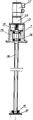
Fig. 1 is the structural representation of the utility model embodiment 1;
Fig. 2 is the left view of Fig. 1;
Fig. 3 is that the A of Fig. 1 is to view;
Fig. 4 is the structural representation of crossbeam described in the utility model embodiment 1;
Fig. 5 is the vertical view of Fig. 4;
Fig. 6 is the A-A cutaway view of Fig. 4;
Fig. 7 is the schematic diagram of crossbeam driving mechanism structure described in the utility model embodiment 1;
Fig. 8 is the structural representation of the utility model embodiment 2;
Fig. 9 is the left view of Fig. 8;
Figure 10 is the structural representation of the utility model embodiment 3;
Figure 11 is the left view of Figure 10;
Figure 12 is the structural representation of crossbeam described in the utility model embodiment 3;
Figure 13 is the vertical view of Figure 12;
Figure 14 is that the A-A of Figure 12 is to cutaway view;
Figure 15 is the B-B cutaway view of Figure 12;
Figure 16 is the C-C cutaway view of Figure 13;
Figure 17 is that the D of Figure 12 is to view;
Figure 18 is the structural representation of the utility model embodiment 4;
Figure 19 is the left view of Figure 18;
Figure 20 is the structural representation of the utility model embodiment 5;
Figure 21 is the left view of Figure 20;
The structural representation of body frame described in Figure 22 the utility model embodiment 5;
Figure 23 is the left view of Figure 22;
Figure 24 is the vertical view of Figure 22;
Figure 25 is the structural representation of crossbeam described in the utility model embodiment 5;
Figure 26 is the vertical view of Figure 25;
Figure 27 is the A-A cutaway view of Figure 25;
Figure 28 is the structural representation of the utility model embodiment 6;
Figure 29 is the left view of Figure 28;
Figure 30 is the structural representation of the utility model embodiment 7;
Figure 31 is the left view of Figure 30;
Figure 32 is the structural representation of crossbeam described in the utility model embodiment 7;
Figure 33 is that the D of Figure 32 is to view;
Figure 34 is that the A-A of Figure 32 is to cutaway view;
Figure 35 is the B-B cutaway view of Figure 32;
Figure 36 is the C-C cutaway view of Figure 32;
Figure 37 is the structural representation of the utility model embodiment 8;
Figure 38 is the left view of Figure 37.
The specific embodiment
Embodiment 1: as Fig. 1 to vertical numerical control tapping machine shown in Figure 7, comprise support 1, body frame 2, crossbeam 3, cutting torch 4 and planar working table 5, body frame 2 is one to be fixedly mounted on the circular pillar 211 on the support 1, be fixed with a supporting plate 212 in the bottom of circular pillar 211, top is fixed with a cantilever beam 213;
Crossbeam 3 is made of cross girder 311, sliding inner sleeve 312, sliding outer cover I 313, sliding outer cover II 314, and cross girder 311 is a rhs-structure, and its front end is fixed with cutting torch seat 6, fixedlys connected with sliding outer cover I313 in the rear end, and cutting torch 4 is installed on the cutting torch seat 6; Sliding inner sleeve 312 is enclosed within on the circular pillar 211 of body frame 2, sliding outer cover I 313 with hold tightly on sliding inner sleeve 312 after sliding outer cover II 314 is fixedlyed connected;
One cover driving crossbeam 3 is installed on the cantilever beam 213 of body frame 2 is the crossbeam transmission mechanism 7 that Z-direction is moved up and down along circular pillar 211, the feed screw nut transmission mechanism of this crossbeam transmission mechanism 7 for constituting by motor 711, motor reducer 712, motor cabinet 713, base 714, shaft coupling 715, screw mandrel 716 and feed screw nut 717; Motor 711 be fixedly mounted on the motor cabinet 713 after motor reducer 712 connects, motor cabinet 713 is fixed on the top of base 714, base 714 is fixed on the cantilever beam 213 of body frame 2; Screw mandrel 716 passes cantilever beam 213, its upper end by be fixed on bearings 718 in the base 714 and be installed in the base 714 and with motor reducer 712 between connect by shaft coupling 715, the lower end is connected with a screw mandrel end seat 720 by bearing 719, and screw mandrel end seat 720 is fixed on the supporting plate 212 of body frame 2; The feed screw nut 717 who is enclosed within on the screw mandrel 716 is movably arranged on the cross girder 311 of crossbeam 3.Screw mandrel 716 rotates, and can move up and down with the circular pillar 211 of overall beam 3 along body frame 2 by feed screw nut 717.
Certainly, crossbeam transmission mechanism 7 can also adopt other transmission mechanism, as gear and rack gear, synchronous belt drive mechanism, pulley and wire cable transmission mechanism or the like.These mechanisms all belong to protection domain of the present utility model, because they all are existing, are not described in detail at this.
Two guide rails 101 are installed in the both sides of support 1, the both sides of planar working table 5 bottom surfaces respectively are equipped with two slide blocks 501 that slide in 1 liang of side rails 101 of support, thereby planar working table 5 is bearing on the support 1, and two guide rails 101 and four slide blocks 501 constitute ways; One cover driving planar working table 5 is installed on support 1 is the table transmission mechanism 8 that X-direction moves back and forth along support 1, the feed screw nut driving transmission mechanism of this table transmission mechanism 8 for constituting by motor 811, motor reducer 812, supporting base 813, shaft coupling 814, bearing block 815, screw mandrel 816 and feed screw nut 817, motor 811 be fixedly mounted on supporting base 813 1 sides after motor reducer 812 connects, supporting base 813 is fixed on the support 1; One end of screw mandrel 816 passes supporting base 813 and is bearing in the supporting base 813 by bearing 818, this end of screw mandrel 816 also with between the motor reducer 812 connects by shaft coupling 814, the other end of screw mandrel 816 is associated with bearing 819 and bearing block 815, and bearing block 815 is fixed on the support 1; Be enclosed within feed screw nut 817 on the screw mandrel 816 and be movably arranged on the bottom surface of planar working table 5.Screw mandrel 816 rotates, and can be with planar working table 5 to be X-direction along support 1 by feed screw nut 817 and move back and forth.
Certainly, table transmission mechanism 8 can also adopt other driving mechanism, as gear and rack gear, synchronous belt drive mechanism, pulley and wire cable transmission mechanism or the like.These mechanisms all belong to protection domain of the present utility model, because they all are existing, are not described in detail at this.
Embodiment 2: as Fig. 8 and vertical numerical control tapping machine shown in Figure 9, on the working face of planar working table 5, be separately installed with master rotor 12 and auxiliary cylinder 13 by four sliding supports 10 and bearing 11, sliding support 10 can adopt the version work of dovetail groove to be connected with planar working table 5, can adjust the centre-to-centre spacing between master rotor 12 and the auxiliary cylinder 13 like this, to adapt to the processing of different-diameter size circular object.Synchronous belt drive mechanism 15 driven rotary that master rotor 11 is driven by the cylinder driving motor 14 that is installed on the planar working table 5.Synchronous belt drive mechanism 15 can also adopt gear drive to substitute.
All the other structures among the embodiment 2 are with embodiment 1.
Embodiment 3: the vertical numerical control tapping machine as shown in Figure 10 to Figure 15, a slide rail 315 respectively is equipped with in end face and bottom surface at the cross girder 311 of crossbeam 3,316 and have a groove 317 in a side, a dolly 16 also is installed on cross girder 311, dolly 16 is a character, be fixed with cutting torch seat 6 on its outer two sides, cutting torch 4 is installed on the cutting torch seat 6, its inner top surface is fixed with a slide block 161 that slides on the slide rail 315 on cross girder 311 end faces, and in the bottom of dolly 16 directive wheel 163 that rolls on the slide rail 315 on cross girder 311 bottom surfaces is installed by guide wheel shaft 162; In dolly 16, be fixed with a groove 317 that sees through cross girder 311 1 sides on the side and stretch into contiguous block 164 in the cross girder 311.One cover driving dolly 16 is installed in cross girder 311 is the dolly driving mechanism 9 that the Y-axis horizontal direction moves back and forth along cross girder 311, the feed screw nut transmission mechanism of dolly driving mechanism 9 for constituting by motor 911, motor reducer 912, motor cabinet 913, shaft coupling 914, bearing block 915, curved cover plate 916, screw mandrel 917 and feed screw nut 918, motor 911 be fixedly mounted on motor cabinet 913 1 sides after motor reducer 912 connects, motor cabinet 913 is fixedly mounted on the otic placode 721 that is fixed in the cross girder 311; One end of screw mandrel 917 passes otic placode 721 and motor cabinet 913 backs are bearing in the motor cabinet 913 by bearing 919, this end of screw mandrel 917 also with between the motor reducer 912 connects by shaft coupling 914, the other end of screw mandrel 816 is bearing on the curved cover plate 916 by bearing 920 and bearing block 815, and curved cover plate 916 is fixed on the end of cross girder 311; Being enclosed within contiguous block 164 on feed screw nut 918 and the dolly 16 on the screw mandrel 917 lives and is connected.Screw mandrel 917 rotates, and can be with dolly 16 to be the Y-axis horizontal direction along cross girder 311 by feed screw nut 918 and move back and forth.
Certainly, dolly transmission mechanism 9 can also adopt other transmission mechanism, as gear and rack gear, synchronous belt drive mechanism, pulley and wire cable transmission mechanism or the like.These mechanisms all belong to protection domain of the present utility model, because they all are existing, are not described in detail at this.
All the other structures among the embodiment 3 are with embodiment 1.
Embodiment 4: as Figure 16 and vertical numerical control tapping machine shown in Figure 17, on the working face of planar working table 5, be separately installed with master rotor 12 and auxiliary cylinder 13 by four sliding supports 10 and bearing 11, sliding support 10 can adopt the version work of dovetail groove to be connected with planar working table 5, can adjust the centre-to-centre spacing between master rotor 12 and the auxiliary cylinder 13 like this, to adapt to the processing of different-diameter size circular object.Synchronous belt drive mechanism 15 driven rotary that master rotor 11 is driven by the cylinder driving motor 14 that is installed on the planar working table 5.Synchronous belt drive mechanism 15 can also adopt gear drive to substitute.
All the other structures among the embodiment 4 are with embodiment 3.
Embodiment 5: as Figure 17 to vertical numerical control tapping machine shown in Figure 26, body frame 2 is square door frame, be to constitute by four root posts 221,222,223,224 that front and back are fixed on the support 1, two outsides of four root posts 221,222,223,224 and the outside, back respectively are equipped with a decorative panel 225 in front and back, between the upper end of front column 221,222, be connected with a block plate 226, be connected with a support plate 227 between the middle part, and a guide rail 228 respectively be installed in the inboard vertical direction of front column 221,222; Be provided with a fixedly middle standing pillar 229 on the support 1 in the center between the rear column 223,224, a guide rail 230 be installed in the inboard vertical direction of middle standing pillar 229;
One cover driving crossbeam 3 is installed on the seat board 226 between front column 221,222 upper ends of body frame 2, and four root posts 221,222,223,224 are the crossbeam transmission mechanism 7 that Z-direction is moved up and down along front and back, the feed screw nut transmission mechanism of this crossbeam transmission mechanism 7 for constituting by motor 711, motor reducer 712, motor cabinet 713, shaft coupling 715, screw mandrel 716 and feed screw nut 717, motor 711 be fixedly mounted on the motor cabinet 713 after motor reducer 712 connects, motor cabinet 713 is fixed on the top of seat board 226; Screw mandrel 716 passes seat board 226, its upper end by be fixed on bearings 718 in the motor cabinet 713 and be installed in the motor cabinet 713 and with motor reducer 712 between connect by shaft coupling 715, the lower end is connected with a screw mandrel end seat 720 by bearing 719, and screw mandrel end seat 720 is fixed on the support plate 227 between front column 221,222 middle parts of body frame 2; The feed screw nut 717 who is enclosed within on the screw mandrel 716 is movably arranged on the cross girder 311 of crossbeam 3.Screw mandrel 716 rotates, and can move up and down with front and back four root posts 221,222,223,224 of overall beam 3 along body frame 2 by feed screw nut 717.
The structure of the planar working table 5 of present embodiment is with embodiment 1.
Embodiment 6: as Figure 27 and vertical numerical control tapping machine shown in Figure 28, body frame 2 is square door frame, be to constitute by four root posts 221,222,223,224 that front and back are fixed on the support 1, two outsides of four root posts 221,222,223,224 and the outside, back respectively are equipped with a decorative panel 225 in front and back, between the upper end of front column 221,222, be connected with a block plate 226, be connected with a support plate 227 between the middle part, and a guide rail 228 respectively be installed in the inboard vertical direction of front column 221,222; Be provided with a fixedly middle standing pillar 229 on the support 1 in the center between the rear column 223,224, a guide rail 230 be installed in the inboard vertical direction of middle standing pillar 229;
One cover driving crossbeam 3 is installed on the seat board 226 between front column 221,222 upper ends of body frame 2, and four root posts 221,222,223,224 are the crossbeam transmission mechanism 7 that Z-direction is moved up and down along front and back, the feed screw nut transmission mechanism of this crossbeam transmission mechanism 7 for constituting by motor 711, motor reducer 712, motor cabinet 713, shaft coupling 715, screw mandrel 716 and feed screw nut 717, motor 711 be fixedly mounted on the motor cabinet 713 after motor reducer 712 connects, motor cabinet 713 is fixed on the top of seat board 226; Screw mandrel 716 passes seat board 226, its upper end by be fixed on bearings 718 in the motor cabinet 713 and be installed in the motor cabinet 713 and with motor reducer 712 between connect by shaft coupling 715, the lower end is connected with a screw mandrel end seat 720 by bearing 719, and screw mandrel end seat 720 is fixed on the support plate 227 between front column 221,222 middle parts of body frame 2; The feed screw nut 717 who is enclosed within on the screw mandrel 716 is movably arranged on the cross girder 311 of crossbeam 3.Screw mandrel 716 rotates, and can move up and down with front and back four root posts 221,222,223,224 of overall beam 3 along body frame 2 by feed screw nut 717.
The structure of the planar working table 5 of present embodiment is with embodiment 2.
Embodiment 7: as Figure 29 and vertical numerical control tapping machine shown in Figure 35, a slide rail 315 respectively is equipped with in end face and bottom surface at the cross girder 311 of crossbeam 3,316 and have a groove 317 in a side, a dolly 16 also is installed on cross girder 311, dolly 16 is a character, be fixed with cutting torch seat 6 on its outer two sides, cutting torch 4 is installed on the cutting torch seat 6, its inner top surface is fixed with a slide block 161 that slides on the slide rail 315 on cross girder 311 end faces, and in the bottom of dolly 16 directive wheel 163 that rolls on the slide rail 315 on cross girder 311 bottom surfaces is installed by guide wheel shaft 162; In dolly 16, be fixed with a groove 317 that sees through cross girder 311 1 sides on the side and stretch into contiguous block 164 in the cross girder 311.One cover driving dolly 16 is installed in cross girder 311 is the dolly transmission mechanism 9 that the Y-axis horizontal direction moves back and forth along cross girder 311, the feed screw nut transmission mechanism of dolly transmission mechanism 9 for constituting by motor 911, motor reducer 912, motor cabinet 913, shaft coupling 914, bearing block 915, curved cover plate 916, screw mandrel 917 and feed screw nut 918, motor 911 be fixedly mounted on motor cabinet 913 1 sides after motor reducer 912 connects, motor cabinet 913 be fixedly mounted on one with crossbeam transmission mechanism 7 in the otic placode 721 that is connected as a single entity of feed screw nut 717 on; One end of screw mandrel 917 passes otic placode 721 and motor cabinet 913 backs are bearing in the motor cabinet 913 by bearing 919, this end of screw mandrel 917 also with between the motor reducer 912 connects by shaft coupling 914, the other end of screw mandrel 917 is supported on the curved cover plate 916 by bearing 920 and bearing block 915, and curved cover plate 916 is fixed on the end of cross girder 311; Being enclosed within contiguous block 164 on feed screw nut 918 and the dolly 16 on the screw mandrel 917 lives and is connected.Screw mandrel 917 rotates, and can be with dolly 16 to be the Y-axis horizontal direction along cross girder 311 by feed screw nut 918 and move back and forth.
All the other structures of present embodiment are with embodiment 5.
Embodiment 8: as Figure 36 and vertical numerical control tapping machine shown in Figure 37, a slide rail 315 respectively is equipped with in end face and bottom surface at the cross girder 311 of crossbeam 3,316 and have a groove 317 in a side, a dolly 16 also is installed on cross girder 311, dolly 16 is a character, be fixed with cutting torch seat 6 on its outer two sides, cutting torch 4 is installed on the cutting torch seat 6, its inner top surface is fixed with a slide block 161 that slides on the slide rail 315 on cross girder 311 end faces, and in the bottom of dolly 16 directive wheel 163 that rolls on the slide rail 315 on cross girder 311 bottom surfaces is installed by guide wheel shaft 162; In dolly 16, be fixed with a groove 317 that sees through cross girder 311 1 sides on the side and stretch into contiguous block 164 in the cross girder 311.One cover driving dolly 16 is installed in cross girder 311 is the dolly transmission mechanism 9 that the Y-axis horizontal direction moves back and forth along cross girder 311, the feed screw nut transmission mechanism of dolly transmission mechanism 9 for constituting by motor 911, motor reducer 912, motor cabinet 913, shaft coupling 914, bearing block 915, curved cover plate 916, screw mandrel 917 and feed screw nut 918, motor 911 be fixedly mounted on motor cabinet 913 1 sides after motor reducer 912 connects, motor cabinet 913 be fixedly mounted on one with crossbeam transmission mechanism 7 in the otic placode 721 that is connected as a single entity of feed screw nut 717 on; One end of screw mandrel 917 passes otic placode 721 and motor cabinet 913 backs are bearing in the motor cabinet 913 by bearing 919, this end of screw mandrel 917 also with between the motor reducer 912 connects by shaft coupling 914, the other end of screw mandrel 816 is supported on the curved cover plate 916 by bearing 920 and bearing block 915, and curved cover plate 916 is fixed on the end of cross girder 311; Being enclosed within contiguous block 164 on feed screw nut 918 and the dolly 16 on the screw mandrel 917 lives and is connected.Screw mandrel 917 rotates, and can be with dolly 16 to be the Y-axis horizontal direction along cross girder 311 by feed screw nut 918 and move back and forth.
All the other structures of present embodiment are with embodiment 6.
Claims (9)
1, vertical numerical control tapping machine, comprise support (1), body frame (2), crossbeam (3), cutting torch (4) and planar working table (5), it is characterized in that described body frame (1) is installed on the support (1), one cover driving crossbeam (3) is installed on body frame (1) is the crossbeam transmission mechanism (7) that Z-direction is moved up and down along body frame (1), crossbeam (3) is connected with crossbeam transmission mechanism (7); Cutting torch (4) is installed on the crossbeam (3); Planar working table (5) is bearing on the support (1) by ways, one cover driving planar working table (5) is installed on support (1) is the table transmission mechanism (8) that X-direction moves back and forth along support (1), planar working table (5) is connected with table transmission mechanism (8).
2, vertical numerical control tapping machine according to claim 1, it is characterized in that on crossbeam (3), also being equipped with a dolly (16), and a cover is installed on crossbeam drives dolly (16) and be the dolly transmission mechanism (9) that the Y-axis horizontal direction moves back and forth along crossbeam, dolly (16) is connected with dolly transmission mechanism (9).
3, vertical numerical control tapping machine according to claim 1 and 2, it is characterized in that upward by sliding support (10) master rotor (12) and auxiliary cylinder (13) being installed, synchronous belt drive mechanism (15) driven rotary that master rotor (12) is driven by the cylinder driving motor (14) that is installed on the planar working table (5) at planar working table (5).
4, vertical numerical control tapping machine according to claim 1 and 2 is characterized in that described crossbeam transmission mechanism (7), dolly transmission mechanism (9), table transmission mechanism (8) can adopt feed screw nut's transmission mechanism.
5, vertical numerical control tapping machine according to claim 4 is characterized in that the motor in described feed screw nut's transmission mechanism is a composite stepper motor.
6, vertical numerical control tapping machine according to claim 4 is characterized in that the motor in described feed screw nut's transmission mechanism is an AC servo motor.
7, vertical numerical control tapping machine according to claim 3 is characterized in that described cylinder driving motor (14) is a composite stepper motor.
8, vertical numerical control tapping machine according to claim 3 is characterized in that described cylinder driving motor (14) is an AC servo motor.
9, vertical numerical control tapping machine according to claim 1 and 2 is characterized in that described cutting torch (4) can replace with welding gun.
Priority Applications (1)
| Application Number | Priority Date | Filing Date | Title |
|---|---|---|---|
| CN 200420035793 CN2702807Y (en) | 2004-05-01 | 2004-05-01 | Vertical digital control perforating machine |
Applications Claiming Priority (1)
| Application Number | Priority Date | Filing Date | Title |
|---|---|---|---|
| CN 200420035793 CN2702807Y (en) | 2004-05-01 | 2004-05-01 | Vertical digital control perforating machine |
Publications (1)
| Publication Number | Publication Date |
|---|---|
| CN2702807Y true CN2702807Y (en) | 2005-06-01 |
Family
ID=34773366
Family Applications (1)
| Application Number | Title | Priority Date | Filing Date |
|---|---|---|---|
| CN 200420035793 Expired - Fee Related CN2702807Y (en) | 2004-05-01 | 2004-05-01 | Vertical digital control perforating machine |
Country Status (1)
| Country | Link |
|---|---|
| CN (1) | CN2702807Y (en) |
Cited By (12)
| Publication number | Priority date | Publication date | Assignee | Title |
|---|---|---|---|---|
| CN100423877C (en) * | 2006-08-02 | 2008-10-08 | 渤海船舶重工有限责任公司 | Hole drilling method for single or dual curved plate |
| CN100446904C (en) * | 2006-10-19 | 2008-12-31 | 庄添财 | Three-dimensional pipe cutter |
| CN100453235C (en) * | 2007-02-13 | 2009-01-21 | 包钢钢威液压件有限责任公司 | Electric perforating method of seamless tube blank |
| CN101961813A (en) * | 2010-10-20 | 2011-02-02 | 常州市新罗特数控机械有限公司 | Integrated planar & cylindrical plasma cutting machine |
| CN102139432A (en) * | 2011-04-02 | 2011-08-03 | 李登平 | Tool device for crane |
| CN102189362A (en) * | 2011-03-23 | 2011-09-21 | 无锡华联精工机械有限公司 | Welding gun lifting mechanism of groove type steel and rivet automatic welding machine |
| CN102784947A (en) * | 2012-07-27 | 2012-11-21 | 林淑琴 | Horizontal hole punching machine |
| CN103418881A (en) * | 2013-08-09 | 2013-12-04 | 青岛东方铁塔股份有限公司 | Cantilever type numerical control plasma flame structural steel three-dimensional cutting machine |
| CN106738061A (en) * | 2017-01-19 | 2017-05-31 | 潘李杰 | A kind of moulding integrated equipment of stamping mold |
| CN106851988A (en) * | 2017-03-20 | 2017-06-13 | 成都蒲江珂贤科技有限公司 | A kind of circuit soft board punch forming integration apparatus |
| CN107009225A (en) * | 2017-03-19 | 2017-08-04 | 成都蒲江珂贤科技有限公司 | A kind of handware surface is gone to expect equipment |
| CN109262284A (en) * | 2018-09-14 | 2019-01-25 | 南京新核复合材料有限公司 | A kind of spherical tank boring device |
-
2004
- 2004-05-01 CN CN 200420035793 patent/CN2702807Y/en not_active Expired - Fee Related
Cited By (18)
| Publication number | Priority date | Publication date | Assignee | Title |
|---|---|---|---|---|
| CN100423877C (en) * | 2006-08-02 | 2008-10-08 | 渤海船舶重工有限责任公司 | Hole drilling method for single or dual curved plate |
| CN100446904C (en) * | 2006-10-19 | 2008-12-31 | 庄添财 | Three-dimensional pipe cutter |
| CN100453235C (en) * | 2007-02-13 | 2009-01-21 | 包钢钢威液压件有限责任公司 | Electric perforating method of seamless tube blank |
| CN101961813A (en) * | 2010-10-20 | 2011-02-02 | 常州市新罗特数控机械有限公司 | Integrated planar & cylindrical plasma cutting machine |
| CN101961813B (en) * | 2010-10-20 | 2012-07-25 | 常州市新罗特数控机械有限公司 | Integrated planar & cylindrical plasma cutting machine |
| CN102189362A (en) * | 2011-03-23 | 2011-09-21 | 无锡华联精工机械有限公司 | Welding gun lifting mechanism of groove type steel and rivet automatic welding machine |
| CN102139432B (en) * | 2011-04-02 | 2014-05-07 | 李登平 | Tool device for crane |
| CN102139432A (en) * | 2011-04-02 | 2011-08-03 | 李登平 | Tool device for crane |
| CN102784947A (en) * | 2012-07-27 | 2012-11-21 | 林淑琴 | Horizontal hole punching machine |
| CN103418881A (en) * | 2013-08-09 | 2013-12-04 | 青岛东方铁塔股份有限公司 | Cantilever type numerical control plasma flame structural steel three-dimensional cutting machine |
| CN103418881B (en) * | 2013-08-09 | 2016-06-08 | 青岛东方铁塔股份有限公司 | Cantilevered mode digital control plasma torch shaped steel solid cutting problem machine |
| CN106738061A (en) * | 2017-01-19 | 2017-05-31 | 潘李杰 | A kind of moulding integrated equipment of stamping mold |
| CN106738061B (en) * | 2017-01-19 | 2019-03-05 | 潘李杰 | A kind of moulding integrated equipment of stamping die |
| CN106738061B8 (en) * | 2017-01-19 | 2019-04-23 | 佛山市富强尔汽车零部件有限公司 | A kind of moulding integrated equipment of stamping die |
| CN107009225A (en) * | 2017-03-19 | 2017-08-04 | 成都蒲江珂贤科技有限公司 | A kind of handware surface is gone to expect equipment |
| CN106851988A (en) * | 2017-03-20 | 2017-06-13 | 成都蒲江珂贤科技有限公司 | A kind of circuit soft board punch forming integration apparatus |
| CN106851988B (en) * | 2017-03-20 | 2019-02-01 | 安庆华璟电子科技有限公司 | A kind of circuit soft board punch forming integration apparatus |
| CN109262284A (en) * | 2018-09-14 | 2019-01-25 | 南京新核复合材料有限公司 | A kind of spherical tank boring device |
Similar Documents
| Publication | Publication Date | Title |
|---|---|---|
| CN201863095U (en) | Carriage movable type three axes numerical control special grinding machine | |
| CN2702807Y (en) | Vertical digital control perforating machine | |
| CN105058142A (en) | Plate type production line capable of automatically charging and discharging | |
| CN201432132Y (en) | Vertical and horizontal dual-purpose numerical control milling machine | |
| CN101314188A (en) | Two-sided lathe bed miller | |
| CN206622510U (en) | A kind of numerical control press workbench | |
| CN109015288A (en) | Sleeping mill carving machine and sleeping mill carving machine control method | |
| CN100340381C (en) | Machine for sawing corner of plate | |
| CN101704194A (en) | Automatic magnetic seat milling device | |
| CN202123874U (en) | Numeric-control engraving machine for large-size wood patterns | |
| CN101612701B (en) | Special movable special drilling, milling and turning machine tool | |
| CN201565784U (en) | Magnetic seat automatic milling device | |
| CN110181611A (en) | A kind of five axis engraving machines | |
| CN116140676A (en) | Full-automatic numerical control edge milling machine for four sides of steel plate | |
| CN206335365U (en) | The Digit Control Machine Tool of linear electric motors driving | |
| CN211000697U (en) | A keyway planer device for relief carving machine | |
| CN201676976U (en) | Punching machine feeding mechanism | |
| CN210615747U (en) | Double-cylinder compression roller device for aluminum plate cutting machine | |
| CN209466291U (en) | A kind of glass fibre reinforced plastics rockbolts automatic angle cutting machine | |
| CN202037222U (en) | Spinning device of metal sheet materials | |
| CN207172448U (en) | A kind of bull vertical stone process equipment | |
| CN201427363Y (en) | Bridge-type stone cutting machine | |
| CN112238264A (en) | Gear shaping device for gear machining for aerospace | |
| CN201677069U (en) | Milling and carving machine tool for surface of workpiece | |
| CN107379288B (en) | A kind of bull vertical stone process equipment |
Legal Events
| Date | Code | Title | Description |
|---|---|---|---|
| C14 | Grant of patent or utility model | ||
| GR01 | Patent grant | ||
| C19 | Lapse of patent right due to non-payment of the annual fee | ||
| CF01 | Termination of patent right due to non-payment of annual fee |