CN2407017Y - Sheet article feeder for continuous electroplating - Google Patents
Sheet article feeder for continuous electroplating Download PDFInfo
- Publication number
- CN2407017Y CN2407017Y CN 99255430 CN99255430U CN2407017Y CN 2407017 Y CN2407017 Y CN 2407017Y CN 99255430 CN99255430 CN 99255430 CN 99255430 U CN99255430 U CN 99255430U CN 2407017 Y CN2407017 Y CN 2407017Y
- Authority
- CN
- China
- Prior art keywords
- chip component
- bearing plate
- lateral transfer
- transfer device
- continuous electroplating
- Prior art date
- Legal status (The legal status is an assumption and is not a legal conclusion. Google has not performed a legal analysis and makes no representation as to the accuracy of the status listed.)
- Expired - Fee Related
Links
Images


Landscapes
- Automatic Assembly (AREA)
Abstract
The utility model is mainly characterized in that a cross conveying device is arranged below a fastener, and a pushing out device is arranged below the cross conveying device which is corresponding to the fastener. The cross conveying device is formed by that a plurality of supporting plates are arranged on a conveying chain in different kinds of separation distances, and sheet-shaped elements with various thickness can be led into holding tanks which are correspondingly and orderly arranged in various widths and in a reliable way to be stably and rapidly conveyed. When the sheet-shaped elements are conveyed to the just lower part of the fastener, the sheet-shaped elements are pushed upward at an appropriate time by the pushing out device so as to carry out loading and can be fast, smoothly, and really conveyed by a clip conveying method one by the matching of the fastener, and the continuous electroplating operation can be realized.
Description
The utility model designs the chip component feeding device that a kind of continuous electroplating is used, particularly relate to a kind of be set as very succinct, install, use very simple and easy, convenient, shape reaches polynary fast, really can to make the material loading of the chip component of desire row continuous electroplating operate more, and extremely realistic suitability, desirability and progressive, and the chip component feeding device used of unprecedented continuous electroplating.
Existing chip component, the lead frame A of IC element as shown in Figure 1 is when implementing continuous electroplating, it is transported to the function mode of toggle clip device, probably as shown in Figure 2, it mainly has the feed mechanism 1 of an assimilating type, is provided with pivot arm 11 and sucker 12 at feed mechanism 1 place; But utilize adsorption section, the plane a of the sucker 12 alignment tab linear element A on this pivot arm 11, as the lead frame of IC element be with the colloid a that is laid in two sides as the adsorption section, plane, then this chip component A that banks up can be so as to firmly being adsorbed; Can do 90 degree rotations and see through pivot arm 11, and the upper end that causes chip component A can just correspond to the clip portion of toggle clip device 2, then under 21 pairs of elastic clip of roof pressure piece 22 are implemented roof pressure and release movement are cooperated, nature, this chip component A just can be by toggle clip device 2 firm grip, and carry one by one and implement the continuous electroplating running.Undeniable, this kind sees through the assimilating type feed mechanism chip component implemented material loading in the function mode of toggle clip device, has the usefulness of seasonable use really; But after the use of going through when long, the dealer desires tangible thoughts, and this still has defective in the actual enforcement, and can wait to improve.That is:
(1) because this provides size, the shape of adsorption section, the plane a of sucker absorption; different through regular meeting because of the difference of chip component A; so essential often enforcement of this sucker changed or regulates under the situation of change; obvious; with regard to the implementation of reality, this just obviously has comparatively trouble, inconvenience and bothersome situation.
(2) as mentioned above, because this chip component A must possess adsorption section, the plane a that is enough to allow sucker absorption is arranged, can make sucker give full play to the action of absorption carrying workpiece, so too little or shape is non-when being plane when the adsorption section, plane of chip component A, nature, this sucker will can't be implemented the action of absorption material loading to its grade fully, and then cause the scope of actual use that the shortcoming of obviously being limited to is arranged.
(3) because this chip component A that banks up implements the action of material loading, be to carry out 90 degree reciprocally swingings by pivot arm, and sucker protracts, after contract and cooperate with action such as air-breathing, outgas, can one by one each chip component be carried to the toggle clip device place, so with regard to the implementation of material loading, the speed of retardation plate linear element material loading will be obviously understood in this multiple action, and then cause also related being affected of efficient of continuous electroplating, and the shortcoming that can't essence improves is arranged.
As from the foregoing, this existing chip component is implemented the material loading running of continuous electroplating, obviously still has the defective in the actual enforcement, and can treat and must be improved.
So, for making above-mentioned defective be able to improve really and effectively, and make the running of the chip component feed mechanism that this continuous electroplating uses, more realistic suitability, desirability and progressive, the planner is with the actual experience of being engaged in various plating with equipment development, manufacturing, special lappingout with great concentration also cooperates the utilization of scientific principle, and with prior art design improved in addition, creates the utility model finally.
The chip component feeding device that provides a kind of continuous electroplating to use is provided main purpose of the present utility model, wherein, borrowing this lateral transfer device is to be listed on the chain with several predetermined spacing design cloth by the plural pieces bearing plate, make and be arranged with regular various width holding tanks in regular turn, the chip component of this all thickness then, under can the situation in electric automatic control, very smooth and easy and certain imports in the corresponding holding tank, can be carried action by quick and stabile enforcement.
The chip component feeding device that provides a kind of continuous electroplating to use is provided a time purpose of the present utility model, wherein, borrowing this lateral transfer device is with the ccontaining chip component of the holding tank of various width, and implement conveying operation one by one, then no matter whether this chip component have the adsorption section, plane, or the area of adsorption section, plane, shape are why, and it all can be transferred really and smoothly, has the polybasic of application really and enlarges the use range effect.
Of the present utility modelly advance a purpose chip component feeding device that provides a kind of continuous electroplating to use is provided, wherein, borrowing this lateral transfer device is that the position is located at the toggle clip device below, and liftout attachment is located at lateral transfer device below with the corresponding position of toggle clip device, when then chip component is delivered under the toggle clip device by the lateral transfer device, push up by going up of liftout attachment in good time, nature, this chip component just can directly be ejected the holding tank that breaks away from e Foerderanlage, and make the upper end just be the toggle clip device clamping, and then finish the material loading action really and fast.
The chip component feeding device that provides a kind of continuous electroplating to use is provided another purpose of the present utility model, it is very succinct that it is set as, install, use very simple and easy, convenient, it is polynary that the material loading running of the chip component of desire row continuous electroplating is reached more fast, really, and extremely realistic suitability, desirability and progressive.
The purpose of this utility model is realized by following technical scheme.According to the chip component feeding device that a kind of continuous electroplating that the utility model proposes is used, it mainly is made of with a liftout attachment jointly lateral transfer device assistant; Wherein: this lateral transfer device, it is located at and is the toggle clip device below of carrying shape; Be to be placed on the frame with the driven axle frame growth shape that two positions are located at the below by the drive shaft assistant that two positions are located at the top, two ends at each are mounted with a sprocket wheel respectively, and be equipped with a chain respectively, drive the conveying operation that circulates and can be driven motor; On two chains, be mounted with the plural pieces bearing plate, each bearing plate and be from bottom to top to be provided with several to wear groove; In addition, on two drive shafts, be installed on the fixed aunular sheet of wearing groove equivalent with bearing plate, the bearing plate that this fixed aunular sheet and just can corresponding being arranged in is carried one by one wear groove; Wherein, the rear side of this each bearing plate lower end presets the bank groove of an indent, but and the rank, location that a bank is set to the bank groove are preset in the front side, be installed in chain one by one after, each bearing plate is formed with the holding tank of a ccontaining chip component each other;
This liftout attachment, it is located at the below of lateral transfer device and is corresponding shape with toggle clip device, be provided with several and eject body and be placed on the strongback, and each bearing plate that divides other correspondence the lateral transfer device wears groove, be provided with the knock-pin that to bear responsibility chip component in the upper end that ejects body; Two ends at strongback are respectively equipped with a chute, can the vertical configuration slippage at the slide rail of frame, one end is to be installed on a push pedal, and this push pedal also just can articulate with the piston rod of a pneumatic cylinder, ejects body and can directly be driven by pneumatic cylinder and carry out vertical ascending, descending action and cause;
Said structure is combined, when each bearing plate setting of this lateral transfer device is positioned at two drive axle position, its holding tank each other forms the bigger V-arrangement shape of opening naturally, but and the smooth and easy input of feed linear element, and the lateral transfer device is carried chip component when corresponding to liftout attachment, this liftout attachment will eject body in good time and rise, and with the knock-pin of the upper end chip component jack-up with correspondence, make and be finished the material loading action by the toggle clip device clamping.
The purpose of this utility model can also further realize by following technical measures.
The chip component feeding device that aforesaid continuous electroplating is used, after each fixed aunular sheet of wherein said lateral transfer device was placed in two drive shafts, its side face and a little more than rank, location, the lower end of bearing plate was respectively worn the groove place and directly be located in.
The chip component feeding device that aforesaid continuous electroplating is used, each bearing plate of wherein said lateral transfer device can be designed as predetermined different value thickness, this clocklike staggered arrangement in regular turn of each bearing plate with different thickness is arranged on chain, and each bearing plate is arranged with predetermined different in width holding tank each other in regular turn.
The chip component feeding device that aforesaid continuous electroplating is used, the knock-pin bottom that ejects the body upper end of wherein said liftout attachment can be provided with elastomerics and bear responsibility, and rubber-like action of giving at any time.
The chip component feeding device that aforesaid continuous electroplating is used, wherein the charging device counterparty to shelf position be provided with one by holding the plate ring, should be arranged on the bearing plate periphery by holding the plate ring, and directly extend the feeding vehicle place of frame below, can give guiding being collected in feeding vehicle to the chip component that leaks folder.
The utility model compared with prior art has tangible advantage and positively effect.By above technical scheme as can be known, the chip component feeding device that the utility model continuous electroplating is used all can fully effectively apply to the utility model by the chip component of all thickness, so obviously have the advantage of using diversification and applied range.
Again owing to be mounted with several fixed aunular sheets at two drive shaft places of lateral transfer device, and the side face by these several fixed aunular sheets is a little more than the cooperation of locating rank, drop into the chip component bottom of holding tank via charging device, can directly be held by the side face of each fixed aunular sheet retaining, and can not fall into the rank, location of holding tank lower end, the gap location between the bank groove, so the destructive phenomenon can not take place to be crushed.
Because this chip component has preferable protection effect, so situation such as can not wound.
Because various width holding tanks that should staggered Boulez, can directly apply to the holding and the material loading running of chip component of various different thickness, and make the assimilating type feed mechanism not be subjected to the size of adsorption section, plane of chip component or the restriction of shape limitation.
In sum, the chip component feeding device that a kind of continuous electroplating of the utility model is used, obviously have the utmost point and meet the effect of dealing with problems that general chip component is implemented the material loading running actual needs of continuous electroplating, though it is complicated, loaded down with trivial details that this device, structure do not seem, yet the dark well-off specifics of executing of whole running imagination, and have the effect of enhancement really, thus be suitable for practicality more, really be a new and innovative, progressive, practical new design.
Concrete structure of the present utility model is provided in detail by following examples and accompanying drawing thereof.
Fig. 1 is the chip component floor map of the lead frame class of general IC element;
Fig. 2 is that the chip component feed mechanism that existing continuous electroplating is used is set as the floor map that had both operated;
Fig. 3 is a schematic perspective view of the present utility model;
Fig. 4 is a perspective view of the present utility model;
Fig. 5 is the bearing plate structural perspective of the utility model lateral transfer device.
Fig. 6 is that the bearing plate of the utility model lateral transfer device is organized the structural representation of establishing mutually;
Fig. 7 is the schematic perspective view of the utility model lateral transfer device;
Fig. 8 is the positive view plane decomposing schematic representation of the utility model;
Fig. 9 is the local amplification view that ejects body among Fig. 8;
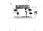
Figure 10 is that the utility model is faced floor map;
Figure 11 is the floor map of the utility model side-looking.The figure number explanation:
A: chip component a: plane adsorbent (colloid)
B: frame C: retaining plate
L: chain K.K ': holding tank
M: motor J: chain drive-belt
1: feed mechanism 10: e Foerderanlage
101: drive shaft 102: driven axle
103: bearing plate 1031: wear groove
1032: bank groove 1033: the rank, location
104: fixed aunular sheet 11: pivot arm
12: sucker 2: toggle clip device
20: liftout attachment 201: eject body
2011: knock-pin 2012: elastomerics
202: strongback 2022: slide rail
2023: push pedal 203: pneumatic cylinder
21: roof pressure piece 22: elastic clip
30: charging device 40: by holding wooden handcart
Below in conjunction with accompanying drawing and preferred embodiment, to the chip component feeding device of using according to the continuous electroplating that the utility model proposes, its concrete structure, feature and effect thereof, describe in detail as after.
At first, see also Fig. 3 to shown in Figure 9, the chip component feeding device that a kind of continuous electroplating of the utility model is used, it mainly includes a lateral transfer device 10 and a liftout attachment 20, wherein;
This lateral transfer device 10 is that the position is located at and is toggle clip device 2 belows (please cooperate shown in Figure 10) of carrying shape; Be drive shaft 101 assistant that is located at the top by two positions with two positions below driven axle 102 be microscler shape planning and be placed on the frame B, two ends at each are mounted with a sprocket wheel W respectively, and, drive the conveying operation that circulates and can be seen through a chain drive-belt J by a CD-ROM drive motor M so as to being equipped with a chain L respectively; Design is mounted with plural pieces bearing plate 103 on two chains, and each bearing plate 103 is from bottom to top to be provided with several to wear groove 1031; In addition, on two drive shafts 101, be provided with the fixed aunular sheet 104 of wearing groove 1031 equivalent with bearing plate 103, and the bearing plate 103 carried one by one of this fixed aunular sheet 104 and just can corresponding being arranged in respectively wear groove 1031; Wherein, this each bearing plate 103 (seeing also Fig. 5, shown in Figure 6), wear the groove 1031 except that from bottom to top being provided with several, rear side in this lower end is preset with the bank groove 1032 of an indent, and but the rank, location 1033 that a bank is set to bank groove 1032 are preset in the front side, after being installed on the chain L one by one, each bearing plate 103 is formed with a holding tank K each other; Again, the thickness of each bearing plate 103 and the different value design that can be scheduled to, and each bearing plate 103 that will have a different thickness is placed on the chain L with staggered the arrangement in regular turn of rule, and each bearing plate 103 is to be arranged with predetermined different in width holding tank K, K ' in regular turn each other; After aforementioned fixed aunular sheet 104 was placed in two drive shafts 101, its side face and a little more than rank 1033, location, the lower end of bearing plate 103 was respectively worn groove 1031 places and be set in.
This liftout attachment 20 (seeing also Fig. 4, Fig. 8, shown in Figure 9), it is located at the below of lateral transfer device 10 and is corresponding shape (please cooperate shown in Figure 10) with toggle clip device 2, it is provided with several and ejects body 201 and be placed on the strongback 202, and each bearing plate 103 of corresponding respectively lateral transfer device 10 wear groove 1031; Two ends of this strongback 202 and be respectively equipped with a chute 2021, it is with two slide rails 2022 places of vertical configuration slippage on frame retaining plate C, reach and at one end be mounted with a push pedal 2023, this push pedal 2023 and the piston rod pivot joint that just can supply a pneumatic cylinder 203, respectively eject body 201 both strongback 202 can directly be promoted by pneumatic cylinder 203, and following slide rail 2022 to carry out ascending, descending action; Wherein, this upper end that ejects body 201 is provided with a knock-pin 2011, and the bottom of this knock-pin 2011 and be subjected to an elastomerics 2012 action of bearing responsibility, and can keep the elasticity running at any time.
Promptly, according to above-mentioned the utility model that constitutes, please cooperate Figure 10, shown in Figure 11 again, because this is installed in each bearing plate 103 on the chain L of lateral transfer device 10, when conveying is moved to the sprocket wheel W place of two drive shafts 101, because of curvature relationship, its mutual holding tank K, (K ') will inevitably form the bigger V-arrangement shape of an opening (seeing also Fig. 3, Fig. 7, shown in Figure 10) automatically, so this charging device 30 just can be so as to dropping into action with chip component A at this smoothly one by one; Again, because this lateral transfer device 10 is belows that the position is located at toggle clip device 2, and each bearing plate 103 is to have planned that from bottom to top several are worn groove 1031, and this liftout attachment 20 is located at lateral transfer device 10 belows with toggle clip device 2 corresponding positions again, and cause respectively eject body 201 be just with bearing plate 103 respectively to wear groove 1031 corresponding, so this drops into the holding tank K of lateral transfer device 10 one by one, the chip component A of (K ') carries when being moved to liftout attachment 20 places, it is overhanging to move piston rod with the pneumatic cylinder 203 of this liftout attachment 20 in good time, then this respectively eject body 201 just can be in related rising, directly being located in the various of bearing plate 103 wears in the groove 1031, and cause upper end knock-pin 2011 can related chip component A to give the direct jack-up of row (to see also Fig. 8 with correspondence, Fig. 9, Figure 10, Figure 11), and then, the elastic clip 22 of toggle clip device 2 can be simultaneously by the 21 extruding actions of roof pressure piece up, under the extruding action cooperates, nature, this is by the upper end of the chip component A of jack-up, just can be quick and firm by clip, reach the effect of high-level efficiency material loading really.Continue it, after this jacking system 20 was finished material loading action with chip component A jack-up, its pneumatic cylinder 203 was descended by action again immediately, and ejecting body 201 can related decline and do the preparation of a vertical motion again.
Because this lateral transfer device 10 is to be the circulation conveying operation, and by charging device 30 counterparties to frame B position, other is provided with one and is located at bearing plate 103 peripheries by holding plate 40 (asking for an interview shown in Figure 10) ring, then when the chip component A of 2 pairs of jack-up material loadings of toggle clip device produces leakage folder phenomenon, the chip component A of this leakage folder can fall back former holding tank K, (K ') again, and continue to be transferred and close at feeding vehicle D by collecting by the guiding of holding plate 30, can implement the material loading running again.
In addition, because each bearing plate 103 holding tank K, (K ') each other of this lateral transfer device 10, it is the different in width that can be designed to preset value, and the holding tank K of variant width, (K '), be rule do interlace mode Boulez (as the staggered Boulez of the holding tank width of two kinds of 3mm, 5mm) in regular turn, so by electric control running, this charging device 30 not only can be according to the thickness of chip component A, and automatically and accurately it is dropped into one by one in each corresponding holding tank K, (K ') of lateral transfer device 10; Simultaneously, each holding tank K, (K ') that chip component A in this bearing carry when being moved to liftout attachment 20 positions, can accurately be braked to do especially and suspend action, and wink is promptly carried out the material loading action of accurate jack-up by the knock-pin 2011 of correspondence; That is, chip component A by all thickness all can fully effectively apply to the utility model, and implemented accurately, fast by the utility model under the situation of material loading action, then with regard to the implementation of reality, the utility model just obviously has the advantage of using diversification and applied range.
Owing to be mounted with several fixed aunular sheets 104 at two drive shafts, 101 places of lateral transfer device 10, and the side face of this fixed aunular sheet 104 is again the rank 1033, location, lower end a little more than bearing plate 103, so each bearing plate 103 is carried the sprocket wheel W position that is moved to two drive shafts 103, and cause each other holding tank K, (K ') is because of the sprocket wheel curvature relationship, and form the bigger V-arrangement shape of opening naturally, and rank, lower end location 1033 and bank groove 1032 mutual banks are established the bonded gap when also enlarging naturally, then the side face by these several fixed aunular sheets 104 is a little more than the cooperation of locating rank 1033, nature, should drop into holding tank K via charging device 30, the chip component A bottom of (K '), can directly be held by the side face of each fixed aunular sheet 104 retaining, and can not fall into the rank, location 1033 of holding tank lower end, gap location between the bank groove 1032, and then the destructive phenomenon can not take place to be crushed at all.
Again, because knock-pin 2011 bottoms of this liftout attachment 20 are directly to be born responsibility by elastomerics 2012, and has suitable shock absorption power, so when chip component A is implemented to eject the material loading action, this chip component A is from can be so as to having preferable protection effect, and unlikely situation such as wound.
Because the utility model is implemented the action of material loading with chip component A, main just carry out simple and direct jack-up action by liftout attachment 20 can be smooth and easy and finish fast, so have the more high efficiency effect except the mode that has the assimilating type material loading now; Especially, the various width holding tank K of Boulez, the planning and design of (K ') should interlock, more can directly apply to the holding and material loading running of chip component of various different thickness, and cause existing assimilating type feed mechanism often to be subjected to the size of adsorption section, plane of chip component or the defective of shape limitation obtains improving really and effectively.
In sum, the chip component feeding device that a kind of continuous electroplating of the utility model is used, be the utilization that present homotype product is not seen,, sincerely ask the auditor to give close examination and gift quasi patent so really met the important document that novel patent application has novelty, progressive and industry utilizability.
Claims (5)
1. chip component feeding device that continuous electroplating is used, it mainly is made of with a liftout attachment jointly lateral transfer device assistant; Wherein:
This lateral transfer device, it is located at and is the toggle clip device below of carrying shape; Be to be placed on the frame with the driven axle frame growth shape that two positions are located at the below by the drive shaft assistant that two positions are located at the top, two ends at each are mounted with a sprocket wheel respectively, and being equipped with a chain respectively, this chain is driven motor and drives the conveying operation that circulates; On two chains, be mounted with the plural pieces bearing plate, each bearing plate and from bottom to top be provided with several and wear groove; In addition, on two drive shafts, be installed on the fixed aunular sheet of wearing groove equivalent with bearing plate, the bearing plate that this fixed aunular sheet and just can corresponding being arranged in is carried one by one wear groove; Wherein, the rear side of this each bearing plate lower end presets the bank groove of an indent, but and the rank, location that a bank is set to the bank groove are preset in the front side, to be installed in chain one by one, each bearing plate is formed with the holding tank of a ccontaining chip component each other;
This liftout attachment, it is located at the below of lateral transfer device and is corresponding shape with toggle clip device, be to be provided with several to eject body and be placed on the strongback, and each bearing plate that divides other correspondence the lateral transfer device wears groove, be provided with the knock-pin that to bear responsibility chip component in the upper end that ejects body; Two ends at strongback are respectively equipped with a chute, and the vertical configuration slippage is at the slide rail of frame, and an end is installed on a push pedal, this push pedal and piston rod pivot joint proper and a pneumatic cylinder, and ejecting body can directly be carried out vertical ascending, descending action by the pneumatic cylinder driving;
Said structure is combined, each bearing plate setting of this lateral transfer device is positioned at two drive axle position, its holding tank each other forms the bigger V-arrangement shape of opening naturally, the smooth and easy input of chip component, and the lateral transfer device corresponds to liftout attachment with the chip component conveying, this liftout attachment will eject body in good time and rise, and the knock-pin of upper end is finished the material loading action with the chip component jack-up of correspondence by the toggle clip device clamping.
2. the chip component feeding device that continuous electroplating according to claim 1 is used, each fixed aunular sheet that it is characterized in that wherein said lateral transfer device is placed in two drive shafts, its side face and a little more than rank, location, the lower end of bearing plate directly is located in and respectively wears the groove place.
3. the chip component feeding device that continuous electroplating according to claim 1 is used, each bearing plate that it is characterized in that wherein said lateral transfer device can be designed as predetermined different value thickness, this clocklike staggered arrangement in regular turn of each bearing plate with different thickness is arranged on chain, and each bearing plate is arranged with predetermined different in width holding tank each other in regular turn.
4. the chip component feeding device that continuous electroplating according to claim 1 is used, the knock-pin bottom that ejects body upper end that it is characterized in that wherein said liftout attachment can be provided with elastomerics and bear responsibility.
5. the chip component feeding device of using according to the described continuous electroplating of arbitrary claim in the claim 1 to 4, it is characterized in that the charging device counterparty to shelf position be provided with one by holding the plate ring, should be arranged on the bearing plate periphery by holding the plate ring, and directly extend the feeding vehicle place of frame below.
Priority Applications (1)
| Application Number | Priority Date | Filing Date | Title |
|---|---|---|---|
| CN 99255430 CN2407017Y (en) | 1999-12-02 | 1999-12-02 | Sheet article feeder for continuous electroplating |
Applications Claiming Priority (1)
| Application Number | Priority Date | Filing Date | Title |
|---|---|---|---|
| CN 99255430 CN2407017Y (en) | 1999-12-02 | 1999-12-02 | Sheet article feeder for continuous electroplating |
Publications (1)
| Publication Number | Publication Date |
|---|---|
| CN2407017Y true CN2407017Y (en) | 2000-11-22 |
Family
ID=34038800
Family Applications (1)
| Application Number | Title | Priority Date | Filing Date |
|---|---|---|---|
| CN 99255430 Expired - Fee Related CN2407017Y (en) | 1999-12-02 | 1999-12-02 | Sheet article feeder for continuous electroplating |
Country Status (1)
| Country | Link |
|---|---|
| CN (1) | CN2407017Y (en) |
Cited By (6)
| Publication number | Priority date | Publication date | Assignee | Title |
|---|---|---|---|---|
| CN102925949A (en) * | 2012-11-12 | 2013-02-13 | 江苏矽研半导体科技有限公司 | Multifunctional loading device for electroplating equipment |
| CN103422141A (en) * | 2013-08-28 | 2013-12-04 | 东莞市五株电子科技有限公司 | Automatic feeding and discharging location system of vertical continuous plating device |
| CN103572355A (en) * | 2012-07-23 | 2014-02-12 | 昆山东威电镀设备技术有限公司 | Auxiliary material-loading device for vertical continuous plating line |
| CN103614763A (en) * | 2013-12-13 | 2014-03-05 | 昆山亿诚化工容器有限公司 | Electroplating device and running method thereof |
| CN103668405A (en) * | 2013-12-30 | 2014-03-26 | 东莞庞思化工机械有限公司 | Dual-drive electroplated-workpiece conveyor |
| CN104532326B (en) * | 2014-12-10 | 2017-08-18 | 深圳市奥美特科技有限公司 | Electroplating device feeding device |
-
1999
- 1999-12-02 CN CN 99255430 patent/CN2407017Y/en not_active Expired - Fee Related
Cited By (9)
| Publication number | Priority date | Publication date | Assignee | Title |
|---|---|---|---|---|
| CN103572355A (en) * | 2012-07-23 | 2014-02-12 | 昆山东威电镀设备技术有限公司 | Auxiliary material-loading device for vertical continuous plating line |
| CN103572355B (en) * | 2012-07-23 | 2016-05-25 | 昆山东威电镀设备技术有限公司 | For the auxiliary feeding device of vertical continuous plating lines |
| CN102925949A (en) * | 2012-11-12 | 2013-02-13 | 江苏矽研半导体科技有限公司 | Multifunctional loading device for electroplating equipment |
| CN103422141A (en) * | 2013-08-28 | 2013-12-04 | 东莞市五株电子科技有限公司 | Automatic feeding and discharging location system of vertical continuous plating device |
| CN103422141B (en) * | 2013-08-28 | 2016-04-06 | 东莞市五株电子科技有限公司 | The automatic loading/unloading station-keeping system of vertical continuous electroplating device |
| CN103614763A (en) * | 2013-12-13 | 2014-03-05 | 昆山亿诚化工容器有限公司 | Electroplating device and running method thereof |
| CN103668405A (en) * | 2013-12-30 | 2014-03-26 | 东莞庞思化工机械有限公司 | Dual-drive electroplated-workpiece conveyor |
| CN103668405B (en) * | 2013-12-30 | 2016-03-16 | 东莞庞思化工机械有限公司 | A kind of Dual-drive electroplated-workpiconveyor conveyor |
| CN104532326B (en) * | 2014-12-10 | 2017-08-18 | 深圳市奥美特科技有限公司 | Electroplating device feeding device |
Similar Documents
| Publication | Publication Date | Title |
|---|---|---|
| CN201313735Y (en) | Magnetoconductive object separation and conveying installation | |
| CN1733552A (en) | Steel bar bounding, clamping and forming method and device thereof | |
| CN2407017Y (en) | Sheet article feeder for continuous electroplating | |
| CN201336274Y (en) | Lamp cap device of automatic screwing energy-saving lamp | |
| CN108910502A (en) | Charging tray automatic propelling device and method for pushing | |
| CN101053865A (en) | Scraper roller transport sieving method and its scraper roller transport sieving machine | |
| CN1262217A (en) | Adsorber | |
| CN1789092A (en) | Warehouse device | |
| CN201952003U (en) | Magazine circulation device and system thereof | |
| CN201120499Y (en) | Feeding mechanism of band sawing machine | |
| CN211392962U (en) | Short rod type part automatic feeding device | |
| CN103407825B (en) | Lift material carrying mechanism and the material collecting device of conducting film assembly | |
| CN103991728A (en) | One-by-one bi-directional feeding device for PCBs | |
| CN205802354U (en) | A kind of interrupter | |
| CN212607709U (en) | Steel sheet storage loading attachment | |
| CN208790647U (en) | Charging tray automatic propelling device | |
| CN110509150B (en) | Chain plate transmission and polishing integrated machine | |
| CN210080572U (en) | Punching press feeder | |
| CN105775801A (en) | Paper conveying part of paper pasting machine | |
| CN201567072U (en) | Finishing line depiler of flat steel | |
| CN218808692U (en) | Coal transportation is with keeping off coal structure | |
| CN206735189U (en) | Chain-plate type material pre-sorting machine | |
| CN111071758A (en) | Short rod type part automatic feeding device | |
| CN201717307U (en) | Pole piece feeding mechanism of accumulator piece packaging device | |
| CN105937325B (en) | Parallel-moving type layer stereo parking apparatus |
Legal Events
| Date | Code | Title | Description |
|---|---|---|---|
| C14 | Grant of patent or utility model | ||
| GR01 | Patent grant | ||
| C19 | Lapse of patent right due to non-payment of the annual fee | ||
| CF01 | Termination of patent right due to non-payment of annual fee |