CN219322256U - Compact mobile module - Google Patents
Compact mobile module Download PDFInfo
- Publication number
- CN219322256U CN219322256U CN202320053594.7U CN202320053594U CN219322256U CN 219322256 U CN219322256 U CN 219322256U CN 202320053594 U CN202320053594 U CN 202320053594U CN 219322256 U CN219322256 U CN 219322256U
- Authority
- CN
- China
- Prior art keywords
- moving table
- base
- guide rail
- stator
- mobile module
- Prior art date
- Legal status (The legal status is an assumption and is not a legal conclusion. Google has not performed a legal analysis and makes no representation as to the accuracy of the status listed.)
- Active
Links
Images


Landscapes
- Linear Motors (AREA)
Abstract
The utility model relates to a compact mobile module, which mainly comprises a base and a moving table, wherein guide rail mounting seats are respectively arranged at two ends of the base in the width direction, guide rails are arranged on each guide rail mounting seat, the moving table is connected with the guide rails, a linear motor is arranged between the base and the moving table and comprises a rotor and a stator, the stator is fixed on the base and comprises two supporting plates which are arranged at intervals, a middle bar connected with the two supporting plates is arranged at one side between the two supporting plates, a row of permanent magnets are arranged on the inner side wall of the supporting plates, each row of permanent magnets comprises N-pole magnets and S-pole magnets which are alternately and sequentially arranged, the moving table is connected with the rotor, the rotor comprises a connecting part and a coil part, and the coil part stretches into between the two supporting plates and is used for being connected with the moving table. The thrust is larger. And this application still has compact structure, advantage that the size is little.
Description
Technical Field
The utility model relates to the field of precision mobile equipment, in particular to a compact mobile module.
Background
In some production fields or detection fields with high movement precision, compact small-sized high-precision mobile modules are generally used. Such modules generally include a base and a motion stage with a linear motor disposed therebetween. The motion table can be driven to move by the linear motor. The corresponding production mechanism or detection mechanism is connected to the motion table.
The existing mobile module generally uses a single-track flat-plate type coreless linear motor. The thrust of the mobile module is relatively small. In some occasions with larger thrust requirements, the mobile module cannot meet the requirements. Therefore, it is necessary to design a mobile module with compact structure and relatively large thrust.
Disclosure of Invention
Based on this, a compact mobile module is provided. The movable module has reasonable layout, compact structure, small size and larger thrust.
The utility model provides a compact mobile module, includes base and motion platform, base width direction' S both ends are provided with the guide rail mount pad respectively, install the cross roller guide rail on every guide rail mount pad, the motion platform links to each other with the cross roller guide rail, be provided with the linear electric motor who is located between two guide rail mount pads between base and the motion platform, linear electric motor includes active cell and stator, be fixed with on the base the stator, the stator is close to one of them guide rail mount pad and keeps away from another guide rail mount pad, the stator includes the backup pad that two intervals set up, one side between two backup pads is provided with the middle piece that links to each other with two supports, install a row of permanent magnet on the inside wall of backup pad, a row of permanent magnet includes N utmost point magnet and the S utmost point magnet of alternate order arrangement, the motion platform with the active cell links to each other, the active cell includes connecting portion and coil portion, the coil portion stretches into between two backup pads, connecting portion are used for linking to each other with the motion platform.
The stator of this application has adopted U-shaped structural design, and the permanent magnet in two backup pads has formed two magnetic track structures for the thrust of linear electric motor itself is great like this. And this application still has compact structure, advantage that the size is little.
In one embodiment, a grating ruler is arranged on the inner side wall of the guide rail mounting seat far away from the stator, a reading head is arranged on one side of the grating ruler, and the reading head is connected with the moving table through a connecting frame.
In one embodiment, the two sides of the moving table, which are positioned on the mover, are respectively provided with a photoelectric sensor for limiting, and the base is provided with an induction plate matched with the photoelectric sensor.
In one embodiment, a plurality of line pressing plates are arranged on the inner wall of the moving table at intervals.
In one embodiment, two ends of the base along the length direction are respectively provided with a bracket positioned at the outer side of the stator, each bracket is provided with an anti-collision block, and the inner wall of the moving table is provided with a groove matched with the anti-collision block.
In one embodiment, a locking plate is detachably connected to one end of the base and one end of the moving table.
Drawings
Fig. 1 is a schematic diagram of a compact mobile module according to an embodiment of the present application.
Fig. 2 is a schematic diagram of an internal structure of a compact mobile module according to an embodiment of the present application.
Fig. 3 is a schematic diagram of the matching relationship between a stator and a mover according to an embodiment of the present application.
Fig. 4 is a schematic diagram of a mover of an embodiment of the present application.
Fig. 5 is a schematic view of the structure of the inner wall of the motion stage of the present application.
Wherein:
110. a motion stage; 120. a base; 130. a guide rail mounting seat; 140. a cross roller guide rail; 150. a locking plate; 160. a stator; 170. a mover; 180. a photoelectric sensor; 190. a wire pressing plate; 210. a grating ruler; 220. a connecting frame; 230. a reading head; 240. a bracket; 250. an anti-collision block; 161. a support plate; 162. a middle bar; 163. a permanent magnet; 171. a connection part; 172. a coil section; 260. a groove; 270. an inductive plate.
Detailed Description
In order that the above objects, features and advantages of the utility model will be readily understood, a more particular description of the utility model will be rendered by reference to the appended drawings.
As shown in fig. 1 and 2, embodiments of the present application provide a compact mobile module. The mobile module includes a base 120 and a motion stage 110. The length direction of the moving module is the moving direction of the moving table 110. The width direction of the mobile module is the direction perpendicular to the length. Guide rail mounting seats 130 are respectively arranged at two ends of the base 120 in the width direction, and the guide rail mounting seats 130 are L-shaped. Mounted on each rail mount 130 is a cross roller rail 140, and the motion stage 110 is coupled to the cross roller rail 140. A linear motor is disposed between the base 120 and the moving table 110 and between the two rail mounts 130. The linear motor comprises a rotor 170 and a stator 160, wherein the stator 160 is fixed on the base 120, and the stator 160 is close to one of the guide rail mounting seats 130 and far away from the other guide rail mounting seat 130. This installation is advantageous in terms of space saving. The stator 160 abuts against the rail mount 130 on one side so that space between the stator 160 and the rail mount 130 on the other side is saved for mounting other mechanisms. The stator 160 includes two support plates 161 disposed at a distance, and a middle bar 162 connected to the two support plates is disposed at one side between the two support plates 161. The middle bar 162 is connected to the two support plates 161 by screws, respectively. A row of permanent magnets 163 is mounted on the inner side wall of each support plate 161, and the row of permanent magnets 163 includes N-pole magnets and S-pole magnets alternately arranged in sequence. The moving stage 110 is connected to the mover 170, and the mover 170 includes a connection portion 171 and a coil portion 172. The connection portion 171 has a block shape, the coil portion 172 has a flat shape, and a wire connected to the coil extends from the connection portion 171. The coil part 172 is inserted between the two support plates 161, and the connection part 171 is connected to the moving table 110.
In operation, after the mover 170 is electrified, the mover 170 moves relative to the stator 160, and then drives the moving table 110 to move together.
When the mobile module of the application bears 10kg, the module size can be as follows: 110mm wide, 404mm long and 32mm thick. The thickness of a conventional mobile module is typically about 75mm if it is to be carried at 10 kg.
In one embodiment, a grating scale 210 is disposed on the inner sidewall of the rail mount 130 away from the stator 160, and the grating scale 210 extends along the length of the stator 160. One side of the grating ruler 210 is provided with a reading head 230, the reading head 230 is connected with the moving table 110 through a connecting frame 220, and corresponding abdication holes can be arranged on the connecting frame 220 for the reading head 230 to cooperate with the grating ruler 210. The moving table 110 can drive the reading head 230 to move during the moving process, and the matching of the reading head 230 and the grating ruler 210 can obtain the moving distance of the moving table 110.
In one embodiment, the moving table 110 is provided with a limiting photoelectric sensor 180 on two sides of the mover 170, and the base 120 is provided with a sensing plate 270 for matching with the photoelectric sensor 180.
Specifically, the photoelectric sensor 180 is used to limit the movement stroke of the movement stage 110. The photosensor 180 moves with the motion stage 110. When the photosensor 180 is operated to the position of the sensing plate 270, the photosensor 180 obtains a detection signal and transmits a control signal to a controller, and the controller controls the mover 170 to stop moving.
In one embodiment, as shown in fig. 2, a plurality of pressing plates 190 are disposed on the inner wall of the moving table 110 at intervals. The pressing line plate 190 is connected to the moving table 110 by screws. Since the photoelectric sensor 180 needs to be provided with corresponding lines, in order to avoid the influence of the lines on the movement of the moving table 110, the present application provides the line pressing plate 190, and the line pressing plate 190 is used for fixing the lines, so that the lines are located between the line pressing plate 190 and the inner wall of the moving table 110.
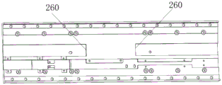
In one embodiment, as shown in fig. 2 and 5, the two ends of the base 120 along the length direction are respectively provided with a bracket 240 located at the outer side of the stator 160, each bracket 240 is provided with an anti-collision block 250, and the inner wall of the moving table 110 is provided with a groove 260 for matching with the anti-collision block 250.
Specifically, when the end surface of the groove 260 on the moving table 110 collides with the crashproof block 250, the moving table 110 is blocked by the crashproof block 250, and the moving table 110 cannot continue to move. The impact block 250 may be coupled to the bracket 240 by a screw. As the material of the above-described impact block 250, a polyurethane material may be used.
In one embodiment, as shown in fig. 1, a locking plate 150 is detachably connected to one end of the base 120 and one end of the moving table 110. The locking plate 150 may be coupled to the base 120 and the motion stage 110 by bolts. When the movement table 110 does not need to be moved, the movement table 110 and the base 120 may be locked to each other by the locking plate 150 such that the movement table 110 cannot move relative to the base 120. When the motion stage 110 is required to perform work, the locking plate 150 may be detached to separate the locking plate 150 from the motion stage 110 and the base 120.
The above examples illustrate only a few embodiments of the utility model, which are described in detail and are not to be construed as limiting the scope of the utility model. It should be noted that it will be apparent to those skilled in the art that several variations and modifications can be made without departing from the spirit of the utility model, which are all within the scope of the utility model. Accordingly, the scope of protection of the present utility model is to be determined by the appended claims.
Claims (6)
1. The compact mobile module comprises a base and a moving table, and is characterized in that two ends of the base in the width direction are respectively provided with a guide rail mounting seat, each guide rail mounting seat is provided with a crossed roller guide rail, the moving table is connected with the crossed roller guide rail,
a linear motor arranged between the base and the moving table and comprising a rotor and a stator, wherein the stator is fixed on the base and is close to one of the guide rail mounting seats and far away from the other guide rail mounting seat, the stator comprises two supporting plates arranged at intervals, one side between the two supporting plates is provided with a middle strip block connected with the two supporting plates, a row of permanent magnets are arranged on the inner side wall of the supporting plates and comprise N-pole magnets and S-pole magnets which are alternately arranged in sequence,
the moving table is connected with the mover, the mover comprises a connecting part and a coil part, the coil part stretches into the space between the two support plates, and the connecting part is used for being connected with the moving table.
2. The compact mobile module of claim 1, wherein a grating scale is disposed on an inner side wall of the guide rail mount far from the stator, a reading head is disposed on one side of the grating scale, and the reading head is connected with the moving table through a connecting frame.
3. The compact mobile module according to claim 1, wherein the two sides of the mover on the moving table are respectively provided with a limiting photoelectric sensor, and the base is provided with a sensing plate for being matched with the photoelectric sensor.
4. A compact mobile module according to claim 3, wherein a plurality of wire pressing plates are arranged on the inner wall of the moving table at intervals.
5. The compact mobile module according to claim 1, wherein brackets located at the outer sides of the stator are respectively arranged at two ends of the base in the length direction, an anti-collision block is arranged on each bracket, and a groove for being matched with the anti-collision block is arranged on the inner wall of the moving table.
6. The compact mobile module as recited in any of claims 1-5, characterised in that a locking plate is removably connected to one end of said base and one end of said motion stage.
Priority Applications (1)
| Application Number | Priority Date | Filing Date | Title |
|---|---|---|---|
| CN202320053594.7U CN219322256U (en) | 2023-01-09 | 2023-01-09 | Compact mobile module |
Applications Claiming Priority (1)
| Application Number | Priority Date | Filing Date | Title |
|---|---|---|---|
| CN202320053594.7U CN219322256U (en) | 2023-01-09 | 2023-01-09 | Compact mobile module |
Publications (1)
| Publication Number | Publication Date |
|---|---|
| CN219322256U true CN219322256U (en) | 2023-07-07 |
Family
ID=87026246
Family Applications (1)
| Application Number | Title | Priority Date | Filing Date |
|---|---|---|---|
| CN202320053594.7U Active CN219322256U (en) | 2023-01-09 | 2023-01-09 | Compact mobile module |
Country Status (1)
| Country | Link |
|---|---|
| CN (1) | CN219322256U (en) |
-
2023
- 2023-01-09 CN CN202320053594.7U patent/CN219322256U/en active Active
Similar Documents
| Publication | Publication Date | Title |
|---|---|---|
| JP4104810B2 (en) | Slide device with built-in movable magnet type linear motor | |
| JP4094799B2 (en) | Slide device with built-in movable magnet type linear motor | |
| US7633188B2 (en) | Sliding device with onboard moving-magnet linear motor | |
| CN219322256U (en) | Compact mobile module | |
| CN215344337U (en) | High-precision high-speed motion platform | |
| CN215824560U (en) | Shaft movement mechanism based on linear driving | |
| CN105765663B (en) | A kind of high precision plane alignment system | |
| CN108533610A (en) | A kind of linear motion module | |
| JP6616507B2 (en) | Linear motor, head unit, surface mounter and single axis robot | |
| CN110524500B (en) | Magnetic suspension guide rail motion platform | |
| CN211254144U (en) | Linear conveying device | |
| CN111917269A (en) | Long-stroke motion system | |
| CN202028928U (en) | Low-loading and high-speed XY working table | |
| CN201112370Y (en) | Two-dimensional motion platform | |
| CN216403103U (en) | Electromagnetic drive circulation line | |
| CN210062426U (en) | Double-guide-rail printing beam | |
| CN212413024U (en) | Linear motor driving platform and machining device | |
| CN102110631B (en) | Precision workpiece table and pipeline facility drive device thereof | |
| CN110349895B (en) | Mechanism for moving by using air cylinder and wafer transmission system | |
| CN209615416U (en) | A kind of gantry is double to drive structure | |
| CN1396693A (en) | Linear motor | |
| JPH08243866A (en) | Two-axis table device driven by linear motor | |
| CN116683694B (en) | Floating driving device | |
| CN215956245U (en) | Linear module | |
| CN220273500U (en) | Integrated direct-drive module |
Legal Events
| Date | Code | Title | Description |
|---|---|---|---|
| GR01 | Patent grant | ||
| GR01 | Patent grant |