CN219211738U - Triaxial drilling structure for automatic lathe - Google Patents
Triaxial drilling structure for automatic lathe Download PDFInfo
- Publication number
- CN219211738U CN219211738U CN202320800766.2U CN202320800766U CN219211738U CN 219211738 U CN219211738 U CN 219211738U CN 202320800766 U CN202320800766 U CN 202320800766U CN 219211738 U CN219211738 U CN 219211738U
- Authority
- CN
- China
- Prior art keywords
- base
- fixedly connected
- seat
- drilling structure
- servo motor
- Prior art date
- Legal status (The legal status is an assumption and is not a legal conclusion. Google has not performed a legal analysis and makes no representation as to the accuracy of the status listed.)
- Active
Links
Images

Classifications
-
- Y—GENERAL TAGGING OF NEW TECHNOLOGICAL DEVELOPMENTS; GENERAL TAGGING OF CROSS-SECTIONAL TECHNOLOGIES SPANNING OVER SEVERAL SECTIONS OF THE IPC; TECHNICAL SUBJECTS COVERED BY FORMER USPC CROSS-REFERENCE ART COLLECTIONS [XRACs] AND DIGESTS
- Y02—TECHNOLOGIES OR APPLICATIONS FOR MITIGATION OR ADAPTATION AGAINST CLIMATE CHANGE
- Y02P—CLIMATE CHANGE MITIGATION TECHNOLOGIES IN THE PRODUCTION OR PROCESSING OF GOODS
- Y02P70/00—Climate change mitigation technologies in the production process for final industrial or consumer products
- Y02P70/10—Greenhouse gas [GHG] capture, material saving, heat recovery or other energy efficient measures, e.g. motor control, characterised by manufacturing processes, e.g. for rolling metal or metal working
Abstract
The utility model discloses a triaxial drilling structure for an automatic lathe, which comprises a base and a mounting seat, wherein the right side of the top of the base is fixedly connected with the mounting seat, the right side of the mounting seat is fixedly connected with a first servo motor, the left side of the mounting seat is movably connected with a transverse screw rod, the outer part of the transverse screw rod is movably sleeved with a threaded sleeve, the left side of the threaded sleeve is fixedly connected with a base, and the front end of the top of the base is welded with a fixing seat. This triaxial drilling structure for automatic lathe is through the right side fixedly connected with mount pad at the base top, starts the first servo motor on mount pad right side to rotatory horizontal lead screw propelling movement thread bush and the base of connecting are left and right sides and are removed, and simultaneously the second servo motor of fixing base front end is also opened together, and the saddle that the guide was equipped with the screw seat slides along vertical lead screw front and back, with this kind of moving means, extension drilling structure's working range has solved the restricted problem of drilling structure removal.
Description
Technical Field
The utility model relates to the technical field of drilling structures, in particular to a triaxial drilling structure for an automatic lathe.
Background
The tapping is an operation of machining internal threaded holes on the surfaces of a shell and a plate by using a cutter bar, so that the two parts which are assembled by using screws, bolts and the like are not connected, in order to accelerate the automatic process, the equipment is often arranged on a lathe, the number of drilling structures can be properly increased when the single drilling boring speed is improved, but the movement track of the structure is often limited, the position of the object to be machined needs to be adjusted by using clamping tools such as a mechanical arm and the like, and the movement range of the drilling structure is very inconvenient to expand.
At present, a novel triaxial drilling structure for an automatic lathe is provided to solve the problems.
Disclosure of Invention
The utility model aims to provide a triaxial drilling structure for an automatic lathe, which aims to solve the problem that the movement of the drilling structure is limited in the background technology.
In order to achieve the above purpose, the present utility model provides the following technical solutions: the utility model provides an automatic triaxial drilling structure for lathe, includes base and mount pad, the right side fixedly connected with mount pad at base top, the right side fixedly connected with first servo motor of mount pad, the left side swing joint of mount pad has horizontal lead screw, the outside activity of horizontal lead screw has cup jointed the screw thread bush, the left side fixedly connected with base of screw thread bush, the front end welding at base top has the fixing base, the second servo motor is installed to the front end of fixing base, the rear swing joint of fixing base has vertical lead screw, the outside of vertical lead screw is provided with the saddle, be provided with the screw thread seat between the inside both ends of saddle, the top fixedly connected with cutter arbor seat of saddle.
Preferably, the threaded sleeve can slide left and right along the transverse screw rod, and the threaded seat can slide back and forth along the longitudinal screw rod.
Preferably, the output shaft of the first servo motor passes through the mounting seat to be fixedly connected with the transverse screw rod, and the output shaft of the second servo motor passes through the fixing seat to be fixedly connected with the longitudinal screw rod.
Preferably, the surface of base and the surface of base are provided with two sets of gag lever posts respectively, the inside of thread bush and saddle bottom is provided with two sets of recesses respectively, the gag lever post inlays inside the recess, the gag lever post is in the coplanar with the recess.
Preferably, three groups of shaft holes are formed between two sides of the inner portion of the cutter bar seat, an eccentric copper sleeve is arranged on the left side of the shaft hole, a rod body is movably arranged between the eccentric copper sleeve and one side of the shaft hole, a clamping head is arranged on the left side of the rod body, three groups of spring retainers are fixedly welded above the right side of the cutter bar seat, clamping blocks are arranged between the right side of the outer portion of the spring retainer and the rod body, and compression springs are arranged between two sides of the outer portion of the spring retainer.
Preferably, the compression springs and the spring retainer are arranged in concentric circles, and the spring retainer and the rod body are positioned on the same vertical plane.
Compared with the prior art, the utility model has the beneficial effects that: the triaxial drilling structure for the automatic lathe not only realizes multidirectional moving drilling structure, realizes stable movement of an auxiliary saddle, but also realizes single implementation of three groups of drilling;
the right side of the top of the base is fixedly connected with a mounting seat, a first servo motor on the right side of the mounting seat is started, the threaded sleeve and a base connected with the threaded sleeve are pushed by a rotating transverse screw rod to move left and right, meanwhile, a second servo motor at the front end of the fixed seat is also started together, and a saddle provided with the threaded seat is guided to slide back and forth along the longitudinal screw rod, so that multidirectional drilling of the structure is realized;
two groups of limiting rods are respectively arranged on the surface of the base and the surface of the base, the bottom ends of the threaded sleeves are clamped outside the two limiting rods through symmetrical grooves while the threaded sleeves slide left and right along the surface of the base, the same auxiliary structure is also arranged between the left threaded seat and the base, and the movable tracks of the threaded sleeves and the base are limited in the moving process of the threaded sleeves and the base;
the top of the saddle is fixedly connected with a cutter bar seat, the rod body is installed in a shaft hole of the saddle through an eccentric copper sleeve, the center height of the rod body is adjusted through the eccentric copper sleeve, after a proper blade is additionally installed in a chuck on the left side, the eccentric copper sleeve drives the rod body to conduct drilling work, the right side of the rod body is fixedly connected with a spring retainer through a clamping block, and the rod body is reset through a compression spring when drilling is finished, so that the next operation is to be performed.
Drawings
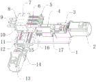
FIG. 1 is a schematic front perspective view of the present utility model;
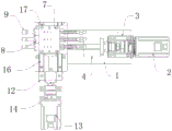
FIG. 2 is a schematic top view of the present utility model;
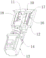
FIG. 3 is a schematic front perspective view of the base of the present utility model;
fig. 4 is a schematic front perspective view of the tool holder of the present utility model.
In the figure: 1. a base; 2. a first servo motor; 3. a mounting base; 4. a thread sleeve; 5. clamping blocks; 6. a compression spring; 7. a cutter bar seat; 8. eccentric copper sleeve; 9. a chuck; 10. a saddle; 11. a screw seat; 12. a base; 13. a second servo motor; 14. a fixing seat; 15. a transverse screw rod; 16. a limit rod; 17. a groove; 18. a longitudinal screw rod; 19. a spring holder; 20. a rod body; 21. and the shaft hole.
Description of the embodiments
The following description of the embodiments of the present utility model will be made clearly and completely with reference to the accompanying drawings, in which it is apparent that the embodiments described are only some embodiments of the present utility model, but not all embodiments. All other embodiments, which can be made by those skilled in the art based on the embodiments of the utility model without making any inventive effort, are intended to be within the scope of the utility model.
Example 1: referring to fig. 1-4, a triaxial drilling structure for an automatic lathe comprises a base 1 and an installation seat 3, wherein the installation seat 3 is fixedly connected to the right side of the top of the base 1, a first servo motor 2 is fixedly connected to the right side of the installation seat 3, a transverse screw rod 15 is movably connected to the left side of the installation seat 3, a threaded sleeve 4 is movably sleeved outside the transverse screw rod 15, a base 12 is fixedly connected to the left side of the threaded sleeve 4, a fixed seat 14 is welded to the front end of the top of the base 12, a second servo motor 13 is mounted at the front end of the fixed seat 14, a longitudinal screw rod 18 is movably connected to the rear of the fixed seat 14, a saddle 10 is arranged outside the longitudinal screw rod 18, a threaded seat 11 is arranged between two ends inside the saddle 10, and a cutter bar seat 7 is fixedly connected to the top of the saddle 10;
the threaded sleeve 4 can slide left and right along the transverse screw rod 15, the threaded seat 11 can slide back and forth along the longitudinal screw rod 18, the output shaft of the first servo motor 2 passes through the mounting seat 3 to be fixedly connected with the transverse screw rod 15, and the output shaft of the second servo motor 13 passes through the fixing seat 14 to be fixedly connected with the longitudinal screw rod 18;
specifically, as shown in fig. 1, 2 and 3, the first servo motor 2 on the right side of the mounting seat 3 is started to push the threaded sleeve 4 and the base 12 connected with the threaded sleeve to move left and right by the rotating transverse screw rod 15, and meanwhile, the second servo motor 13 on the front end of the fixing seat 14 is also started together to guide the saddle 10 provided with the threaded seat 11 to slide back and forth along the longitudinal screw rod 18, so that the working range of the drilling structure is expanded in such a moving manner.
Example 2: two groups of limiting rods 16 are respectively arranged on the surface of the base 1 and the surface of the base 12, two groups of grooves 17 are respectively arranged in the threaded sleeve 4 and the bottom end of the saddle 10, the limiting rods 16 are embedded in the grooves 17, and the limiting rods 16 and the grooves 17 are positioned on the same plane;
specifically, as shown in fig. 1, 2 and 3, while the screw sleeve 4 slides left and right along the surface of the base 1, the bottom ends thereof are clamped outside the two limit rods 16 through symmetrical grooves 17, the same auxiliary structure is also arranged between the screw seat 11 and the base 12 on the left side, and the movable rails of the screw sleeve 4 and the base 12 are limited in the moving process of the screw sleeve and the base 12, so that the stability of the drilling structure during operation is maintained.
Example 3: three groups of shaft holes 21 are formed between two sides of the inside of the cutter bar seat 7, an eccentric copper sleeve 8 is arranged on the left side of the shaft hole 21, a rod body 20 is movably arranged between the eccentric copper sleeve 8 and one side of the shaft hole 21, a clamping head 9 is arranged on the left side of the rod body 20, three groups of spring retainers 19 are fixedly welded above the right side of the cutter bar seat 7, clamping blocks 5 are arranged between the right side of the outside of the spring retainers 19 and the rod body 20, compression springs 6 are arranged between two sides of the outside of the spring retainers 19, the compression springs 6 and the spring retainers 19 are concentrically arranged, and the spring retainers 19 and the rod body 20 are positioned on the same vertical plane;
specifically, as shown in fig. 1 and 4, the rod body 20 is mounted in the shaft hole 21 of the saddle 10 by means of the eccentric copper sleeve 8, and the center height of the rod body 20 is adjusted by the eccentric copper sleeve, after a proper blade is additionally mounted in the left chuck 9, the eccentric copper sleeve 8 drives the rod body 20 to perform drilling work, and the right side of the rod body 20 is fixedly connected with the spring retainer 19 by using the clamping block 5, so that the compression spring 6 resets the rod body when drilling is finished, thereby improving the machining efficiency and guaranteeing the structural accuracy.
Working principle: when the drilling device is used, the first servo motor 2 on the right side of the mounting seat 3 is started firstly, the threaded sleeve 4 and the base 12 connected with the threaded sleeve are pushed by the rotating transverse screw rod 15 to move left and right, meanwhile, the second servo motor 13 at the front end of the fixed seat 14 is also started together, the saddle 10 provided with the threaded seat 11 is guided to slide back and forth along the longitudinal screw rod 18, the bottom end of the threaded sleeve 4 is clamped outside the two limiting rods 16 through symmetrical grooves 17 while sliding left and right along the surface of the base 1, the same auxiliary structure is also arranged between the threaded seat 11 on the left side and the base 12, the movable rails of the threaded sleeve 4 and the base 12 are limited in the moving process of the threaded sleeve 4 and the base 12, the stability of the drilling structure in operation is maintained, the rod body 20 is installed in the shaft hole 21 of the saddle 10 through the eccentric copper sleeve 8, after a proper blade is additionally arranged in the left chuck 9, the rod body 20 is driven to perform drilling operation through the eccentric copper sleeve 8, the right side of the rod body 20 is also fixedly connected with the spring holder 19 through the clamping block 5, and the spring 6 is quickly compressed when the drilling operation is finished.
It will be evident to those skilled in the art that the utility model is not limited to the details of the foregoing illustrative embodiments, and that the present utility model may be embodied in other specific forms without departing from the spirit or essential characteristics thereof. The present embodiments are, therefore, to be considered in all respects as illustrative and not restrictive, the scope of the utility model being indicated by the appended claims rather than by the foregoing description, and all changes which come within the meaning and range of equivalency of the claims are therefore intended to be embraced therein. Any reference sign in a claim should not be construed as limiting the claim concerned.
Claims (6)
1. The utility model provides an automatic triaxial drilling structure for lathe, includes base (1) and mount pad (3), its characterized in that: the right side fixedly connected with mount pad (3) at base (1) top, the right side fixedly connected with first servo motor (2) of mount pad (3), the left side swing joint of mount pad (3) has horizontal lead screw (15), the outside activity of horizontal lead screw (15) has cup jointed threaded sleeve (4), the left side fixedly connected with base (12) of threaded sleeve (4), the front end welding at base (12) top has fixing base (14), second servo motor (13) are installed to the front end of fixing base (14), the rear swing joint of fixing base (14) has vertical lead screw (18), the outside of vertical lead screw (18) is provided with saddle (10), be provided with screw seat (11) between the inside both ends of saddle (10), the top fixedly connected with cutter arbor seat (7) of saddle (10).
2. The triaxial drilling structure for an automatic lathe according to claim 1, characterized in that: the thread sleeve (4) can slide left and right along the transverse screw rod (15), and the thread seat (11) can slide back and forth along the longitudinal screw rod (18).
3. The triaxial drilling structure for an automatic lathe according to claim 1, characterized in that: the output shaft of the first servo motor (2) passes through the mounting seat (3) to be fixedly connected with the transverse screw rod (15), and the output shaft of the second servo motor (13) passes through the fixing seat (14) to be fixedly connected with the longitudinal screw rod (18).
4. The triaxial drilling structure for an automatic lathe according to claim 1, characterized in that: two groups of limiting rods (16) are respectively arranged on the surface of the base (1) and the surface of the base (12), two groups of grooves (17) are respectively arranged in the threaded sleeve (4) and the bottom end of the saddle (10), the limiting rods (16) are embedded in the grooves (17), and the limiting rods (16) and the grooves (17) are located on the same plane.
5. The triaxial drilling structure for an automatic lathe according to claim 1, characterized in that: three groups of shaft holes (21) are formed between two sides of the inner portion of the cutter bar seat (7), an eccentric copper sleeve (8) is arranged on the left side of the shaft hole (21), a rod body (20) is movably arranged between the eccentric copper sleeve (8) and one side of the shaft hole (21), a clamping head (9) is arranged on the left side of the rod body (20), three groups of spring retainers (19) are fixedly welded above the right side of the cutter bar seat (7), clamping blocks (5) are arranged between the right side of the outer portion of the spring retainers (19) and the rod body (20), and compression springs (6) are arranged between two sides of the outer portion of the spring retainers (19).
6. The triaxial drilling structure for an automatic lathe according to claim 5, characterized in that: the compression springs (6) and the spring retainer (19) are arranged in concentric circles, and the spring retainer (19) and the rod body (20) are positioned on the same vertical plane.
Priority Applications (1)
| Application Number | Priority Date | Filing Date | Title |
|---|---|---|---|
| CN202320800766.2U CN219211738U (en) | 2023-04-12 | 2023-04-12 | Triaxial drilling structure for automatic lathe |
Applications Claiming Priority (1)
| Application Number | Priority Date | Filing Date | Title |
|---|---|---|---|
| CN202320800766.2U CN219211738U (en) | 2023-04-12 | 2023-04-12 | Triaxial drilling structure for automatic lathe |
Publications (1)
| Publication Number | Publication Date |
|---|---|
| CN219211738U true CN219211738U (en) | 2023-06-20 |
Family
ID=86745778
Family Applications (1)
| Application Number | Title | Priority Date | Filing Date |
|---|---|---|---|
| CN202320800766.2U Active CN219211738U (en) | 2023-04-12 | 2023-04-12 | Triaxial drilling structure for automatic lathe |
Country Status (1)
| Country | Link |
|---|---|
| CN (1) | CN219211738U (en) |
-
2023
- 2023-04-12 CN CN202320800766.2U patent/CN219211738U/en active Active
Similar Documents
| Publication | Publication Date | Title |
|---|---|---|
| CN113941861A (en) | Turning and milling integrated machine tool | |
| CN216503388U (en) | Turning and milling combined type machine tool | |
| CN219211738U (en) | Triaxial drilling structure for automatic lathe | |
| CN216801919U (en) | Numerical control forming machine for end face of aviation conduit | |
| CN110216481A (en) | The method of its processing valve body of digital control vertical lathe and application | |
| CN108356358A (en) | A kind of beveler that error rate is low | |
| CN211566209U (en) | Six-station turntable type combined special machine for wooden fingers | |
| CN211438920U (en) | Novel high-speed turning and drilling compound machine | |
| CN209717106U (en) | A kind of drilling processing automatic fixture clamping fixture table | |
| CN208231001U (en) | A kind of beveler that error rate is low | |
| CN108381219B (en) | Bidirectional synchronous centering positioning device for automobile brake bracket | |
| CN214488893U (en) | Radial drill is used in spot facing work | |
| CN219853291U (en) | Automatic drilling machine for guide rail | |
| CN216881728U (en) | High-precision mechanical lathe | |
| CN219255111U (en) | High-precision automatic machine tool device | |
| CN216359349U (en) | Inner wall machining device for large-size train brake cylinder | |
| CN219275142U (en) | Positioning fixture for planer type milling machine machining | |
| CN215546626U (en) | Turning and milling combined machining center with front spindle moving structure | |
| CN212095218U (en) | Double-turret combined machining machine tool | |
| CN210125885U (en) | Novel milling machine | |
| CN215747136U (en) | Double-end double-process engraving machine | |
| CN219766987U (en) | Machine tool for machining bevel gear | |
| CN215144916U (en) | Boring machine for machining cylinder bottom rod head | |
| CN218575509U (en) | Double-cutter tower turning and milling composite device | |
| CN219766844U (en) | Automatic deep hole boring machine |
Legal Events
| Date | Code | Title | Description |
|---|---|---|---|
| GR01 | Patent grant | ||
| GR01 | Patent grant |