CN219190593U - Curing and forming device for processing water permeable bricks - Google Patents
Curing and forming device for processing water permeable bricks Download PDFInfo
- Publication number
- CN219190593U CN219190593U CN202223300451.6U CN202223300451U CN219190593U CN 219190593 U CN219190593 U CN 219190593U CN 202223300451 U CN202223300451 U CN 202223300451U CN 219190593 U CN219190593 U CN 219190593U
- Authority
- CN
- China
- Prior art keywords
- storage box
- curing
- water permeable
- permeable bricks
- molding device
- Prior art date
- Legal status (The legal status is an assumption and is not a legal conclusion. Google has not performed a legal analysis and makes no representation as to the accuracy of the status listed.)
- Active
Links
Images


Abstract
The utility model discloses a solidification forming device for processing water permeable bricks, which comprises a machine table, wherein a transmission machine body is arranged at the central position of the top end of the machine table, a first rotary driving piece is arranged at the central position of the bottom of the transmission machine body, a disc is arranged at the top end of the first rotary driving piece, a bump is arranged on one side of the top end of the disc, a gear is rotationally connected inside the transmission machine body on one side of the bump, a vertical shaft is arranged at the central position of the top end of the gear, the top end of the vertical shaft extends to the outside of the transmission machine body and is provided with a bearing table, and a forming die with equal intervals is arranged at the top end of the bearing table. The utility model not only achieves the aim of multi-station sequential solidification molding, but also improves the processing efficiency of the permeable brick when the solidification molding device is used, accelerates the solidification rate of the permeable brick slurry, further improves the solidification efficiency of the permeable brick when the solidification molding device is used, reduces the phenomenon that the slurry is deposited and condensed in the storage box, and further ensures the quality of the slurry in the storage box.
Description
Technical Field
The utility model relates to the technical field of water permeable brick processing, in particular to a curing and forming device for water permeable brick processing.
Background
The permeable brick is usually called a permeable brick, which belongs to a novel environment-friendly building material, the raw materials are mainly formed at high pressure by adopting environment-friendly materials such as cement, sand, slag, fly ash and the like, the permeable brick can not be fired at high temperature, the whole brick is formed by one-time compression and can not be pressed in a layered manner to form a homogeneous brick which is consistent up and down and is not layered, and the first water drill is required to be injected into a corresponding mold for curing and forming process treatment during production and processing, so that a corresponding curing and forming device is required during use.
The utility model relates to a curing molding device for processing a sand-based water permeable brick, which comprises a workbench, wherein a supporting seat is welded at the bottom of the workbench, a weight-reducing groove is formed in the side surface of the supporting seat, a driving cylinder is horizontally arranged on the upper surface of the workbench, an L-shaped rod is fixedly connected to the output end of the driving cylinder, a molding plate is fixedly connected to the top of the L-shaped rod, a first molding cavity is formed in the upper surface of the molding plate, a second molding cavity is formed in the other side of the first molding cavity, and a grouting mechanism and a quick-drying mechanism are fixedly connected at the same time through the U-shaped rod.
Disclosure of Invention
The utility model aims to provide a curing and forming device for processing water permeable bricks, which solves the problems that in the prior art, the curing and forming device can better cure and form the water permeable bricks and can dry the water permeable bricks so as to accelerate the curing efficiency of the water permeable bricks, but is generally inconvenient to perform multi-station sequential curing and forming treatment on the water permeable bricks, so that the processing efficiency of the water permeable bricks is difficult to reach a given expected.
In order to achieve the above purpose, the present utility model provides the following technical solutions: the utility model provides a solidification forming device that brick processing was used that permeates water, includes the board, the central point department of board top is equipped with the transmission organism, the central point department of transmission organism bottom installs first rotary driving spare, the top of first rotary driving spare is equipped with the disc, one side on disc top is equipped with the lug, the inside rotation of transmission organism of lug one side is connected with the gear, the central point department on gear top is equipped with the vertical scroll, the top of vertical scroll extends to the outside of transmission organism and is equipped with the plummer, the top of plummer is equipped with equidistant forming die, the board top of transmission organism one side is equipped with the frame, one side at frame top is equipped with the storage case, the top of storage case extends to the outside of frame, one side of storage case bottom is equipped with row material pipe, the top of row material pipe extends to the inside of storage case, the storage case bottom of row material pipe both sides all is equipped with the heating block.
Preferably, an annular limiting frame is arranged at the top end of the machine table outside the transmission machine body so as to position the limiting rod.
Preferably, a material injection port is arranged at the center of the top end of the material storage box, and the bottom end of the material injection port extends to the inside of the material storage box so as to store the slurry in the inside of the material storage box.
Preferably, the central position in the storage box is rotationally connected with a stirring shaft, and the outer walls on two sides of the stirring shaft are provided with equidistant stirring blades so as to stir the slurry in the storage box.
Preferably, a second rotary driving piece is installed on the outer wall of one side of the storage box, and one end of the second rotary driving piece extends to the inside of the storage box and is fixedly connected with one end of the stirring shaft so as to drive the stirring shaft to rotate.
Preferably, a lifting driving piece is arranged at the top of the frame at one side of the storage box, and a bearing plate is arranged at the bottom end of the lifting driving piece so as to drive the bearing plate to lift.
Preferably, a heating plate is installed at the central position of the bottom end of the bearing plate so as to accelerate the solidification efficiency of the slurry.
Preferably, both sides inside the annular limiting frame are all connected with the limiting rod in a sliding way, and the top end of the limiting rod extends to the outside of the annular limiting frame and is fixedly connected with the bottom end of the bearing table so as to limit the rotation amplitude of the bearing table.
Compared with the prior art, the utility model has the beneficial effects that: the curing and forming device for processing the water permeable bricks not only achieves the aim of multi-station sequential curing and forming, but also improves the processing efficiency of the water permeable bricks when the curing and forming device is used, accelerates the solidification rate of slurry of the water permeable bricks, further improves the curing efficiency of the water permeable bricks when the curing and forming device is used, reduces the phenomenon that the slurry is deposited and condensed in the storage box, and further ensures the quality of the slurry in the storage box;
(1) The disc is driven to rotate through the first rotary driving piece, the disc drives the gear to slowly rotate through the convex blocks, the gear drives the bearing table to slowly rotate through the vertical shaft, at the moment, the lower end of the limiting rod is positioned in the annular limiting frame to slide, so that the rotating amplitude of the bearing table is limited, the bearing table is more stable when rotating, and the slurry can be sequentially injected into the forming die due to the fact that a plurality of groups of forming dies are arranged at the top end of the bearing table, the purpose of multi-station sequential solidification forming is achieved, and therefore the processing efficiency of the permeable bricks is improved when the solidification forming device is used;
(2) The lifting driving piece drives the bearing plate to move downwards, so that the bearing plate drives the heating plate to move downwards to the upper part of the forming die, and the heat energy released by the heating plate can be used for drying the water permeable brick slurry in the forming die so as to accelerate the solidification rate of the water permeable brick slurry, thereby improving the solidification efficiency of the water permeable brick when the solidification forming device is used;
(3) The stirring shaft is driven to rotate through the second rotary driving piece, so that the stirring shaft drives the stirring blades to rotate inside the storage box, and the slurry inside the storage box can be stirred through the stirring blades, so that the activity of molecules inside the slurry is improved, the phenomenon that the slurry is located inside the storage box to precipitate and coagulate can be reduced, and the quality of the slurry inside the storage box is ensured.
Drawings
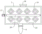
FIG. 1 is a schematic cross-sectional elevation view of the present utility model;
FIG. 2 is a schematic cross-sectional view of a storage tank of the present utility model;
FIG. 3 is a schematic top view of the stage of the present utility model;
FIG. 4 is a schematic top view of a gear according to the present utility model;
fig. 5 is a schematic top view of the annular limiting frame of the present utility model.
In the figure: 1. a machine table; 2. a frame; 3. a transmission body; 4. a carrying platform; 5. a forming die; 6. a discharge pipe; 7. a storage box; 8. a lifting driving member; 9. a carrying plate; 10. a heating plate; 11. a vertical shaft; 12. a gear; 13. a disc; 14. a limit rod; 15. an annular limit frame; 16. a first rotary drive member; 17. a second rotary driving member; 18. a material injection port; 19. stirring blades; 20. a stirring shaft; 21. a bump; 22. and heating the block.
Detailed Description
The technical solutions in the embodiments of the present utility model will be clearly and completely described below with reference to the accompanying drawings in the embodiments of the present utility model. All other embodiments, which can be made by those skilled in the art based on the embodiments of the utility model without making any inventive effort, are intended to be within the scope of the utility model.
Referring to fig. 1-5, an embodiment of the present utility model is provided: the curing and forming device for processing the water permeable bricks comprises a machine table 1, wherein a transmission machine body 3 is arranged at the center position of the top end of the machine table 1, and an annular limiting frame 15 is arranged at the top end of the machine table 1 outside the transmission machine body 3;
when in use, the annular limiting frame 15 is arranged at the top end of the machine table 1 outside the transmission machine body 3 so as to carry out positioning treatment on the limiting rod 14;
the two sides of the inside of the annular limiting frame 15 are both in sliding connection with limiting rods 14, and the top ends of the limiting rods 14 extend to the outside of the annular limiting frame 15 and are fixedly connected with the bottom end of the bearing table 4;
when in use, the lower end of the limiting rod 14 is positioned in the annular limiting frame 15 to slide so as to limit the rotation amplitude of the bearing table 4;
a first rotary driving piece 16 is arranged at the central position of the bottom of the transmission machine body 3, a disc 13 is arranged at the top end of the first rotary driving piece 16, a lug 21 is arranged on one side of the top end of the disc 13, a gear 12 is rotatably connected inside the transmission machine body 3 on one side of the lug 21, a vertical shaft 11 is arranged at the central position of the top end of the gear 12, the top end of the vertical shaft 11 extends to the outside of the transmission machine body 3 and is provided with a bearing table 4, an equidistant forming die 5 is arranged at the top end of the bearing table 4, a machine frame 2 is arranged at the top of the machine table 1 on one side of the transmission machine body 3, a storage box 7 is arranged at one side of the top of the machine frame 2, a material injection port 18 is arranged at the central position of the top end of the storage box 7, and the bottom end of the material injection port 18 extends to the inside of the storage box 7;
in use, the slurry is injected into the interior of the storage tank 7 through the injection port 18 so as to be stored in the interior of the storage tank 7;
a stirring shaft 20 is rotatably connected to the central position inside the storage box 7, and equidistant stirring blades 19 are arranged on the outer walls of the two sides of the stirring shaft 20;
when in use, the stirring shaft 20 drives the stirring blade 19 to rotate so as to stir the slurry in the storage box 7;
a second rotary driving piece 17 is arranged on the outer wall of one side of the storage box 7, and one end of the second rotary driving piece 17 extends into the storage box 7 and is fixedly connected with one end of a stirring shaft 20;
in use, the second rotary driving piece 17 is turned on to drive the stirring shaft 20 to rotate;
a lifting driving piece 8 is arranged at the top of the machine frame 2 at one side of the storage box 7, and a bearing plate 9 is arranged at the bottom end of the lifting driving piece 8;
when in use, the lifting driving piece 8 is opened so as to drive the bearing plate 9 to lift;
a heating plate 10 is arranged at the central position of the bottom end of the bearing plate 9;
when the slurry curing device is used, the heating plate 10 is driven by the bearing plate 9 to move downwards to the upper part of the forming die 5, so that the heating plate 10 releases heat energy to dry the slurry in the forming die 5, and the curing efficiency of the slurry is accelerated;
one side of the bottom end of the storage box 7 is provided with a discharge pipe 6, the top end of the discharge pipe 6 extends to the inside of the storage box 7, and the bottoms of the storage boxes 7 on two sides of the discharge pipe 6 are provided with heating blocks 22.
When the embodiment of the application is used, firstly, the slurry is injected into the storage box 7 through the material injection port 18, the heat energy is released into the storage box 7 through the heating block 22 so as to ensure that the slurry is in a high-temperature state, then the stirring shaft 20 is driven to rotate through the second rotary driving piece 17, the stirring shaft 20 drives the stirring blades 19 to be positioned in the storage box 7 to rotate, the slurry in the storage box 7 can be stirred through the stirring blades 19, so that the activity of molecules in the slurry is improved, the phenomenon that the slurry is deposited and condensed in the storage box 7 can be reduced, then the valve on the outer wall of the material discharging pipe 6 is opened, the slurry in the storage box 7 falls into the forming die 5 through the material discharging pipe 6 so that the slurry is positioned in the forming die 5 to be solidified and formed into the water permeable bricks, the disc 13 is driven to rotate by the first rotary driving piece 16, the disc 13 drives the gear 12 to slowly rotate through the convex blocks 21, the gear 12 drives the bearing table 4 to slowly rotate through the vertical shaft 11, at the moment, the lower end of the limiting rod 14 is positioned in the annular limiting frame 15 to slide, so that the rotating amplitude of the bearing table 4 is limited, the bearing table 4 is more stable when rotating, the slurry can be sequentially injected into the forming die 5 due to the fact that the plurality of groups of forming dies 5 are arranged at the top end of the bearing table 4, the purpose of multi-station sequential curing and forming is achieved, finally, the bearing plate 9 is driven to move downwards through the lifting driving piece 8, the bearing plate 9 drives the heating plate 10 to move downwards to the upper side of the forming die 5, so that the heat energy released by the heating plate 10 can dry the water permeable brick slurry in the forming die 5 to accelerate the solidification rate of the water permeable brick slurry, thereby completing the use of the curing and molding device.
Claims (8)
1. The utility model provides a solidification forming device that brick processing was used that permeates water, its characterized in that includes board (1), the central point department of board (1) top is equipped with transmission organism (3), the central point department of transmission organism (3) bottom installs first rotary drive spare (16), the top of first rotary drive spare (16) is equipped with disc (13), one side on disc (13) top is equipped with lug (21), the inside rotation of transmission organism (3) of lug (21) one side is connected with gear (12), the central point department on gear (12) top is equipped with vertical scroll (11), the top of vertical scroll (11) extends to the outside of transmission organism (3) and is equipped with plummer (4), the top of plummer (4) is equipped with equidistant forming die (5), board (1) top of transmission organism (3) one side is equipped with frame (2), one side at frame (2) top is equipped with storage box (7), the top of storage box (7) extends to the outside of frame (2), the top of storage box (7) is equipped with row material pipe (6) top of arranging (6), the bottoms of the storage boxes (7) at the two sides of the discharge pipe (6) are provided with heating blocks (22).
2. The curing and molding device for processing water permeable bricks of claim 1, wherein: an annular limiting frame (15) is arranged at the top end of the machine table (1) at the outer side of the transmission machine body (3).
3. The curing and molding device for processing water permeable bricks of claim 1, wherein: the center position at the top end of the storage box (7) is provided with a material injection port (18), and the bottom end of the material injection port (18) extends to the inside of the storage box (7).
4. The curing and molding device for processing water permeable bricks of claim 1, wherein: the stirring shaft (20) is rotatably connected to the central position inside the storage box (7), and equidistant stirring blades (19) are arranged on the outer walls of the two sides of the stirring shaft (20).
5. The curing and molding device for processing water permeable bricks of claim 4, wherein: the outer wall of one side of the storage box (7) is provided with a second rotary driving piece (17), and one end of the second rotary driving piece (17) extends to the inside of the storage box (7) and is fixedly connected with one end of the stirring shaft (20).
6. The curing and molding device for processing water permeable bricks of claim 1, wherein: lifting driving parts (8) are arranged at the top of the machine frame (2) at one side of the storage box (7), and a bearing plate (9) is arranged at the bottom end of each lifting driving part (8).
7. The curing and molding device for processing water permeable bricks of claim 6, wherein: a heating plate (10) is arranged at the central position of the bottom end of the bearing plate (9).
8. The curing and molding device for processing water permeable bricks according to claim 2, wherein: both sides inside annular spacing frame (15) are all sliding connection has gag lever post (14), the top of gag lever post (14) extends to the outside of annular spacing frame (15) and with the bottom fixed connection of plummer (4).
Priority Applications (1)
| Application Number | Priority Date | Filing Date | Title |
|---|---|---|---|
| CN202223300451.6U CN219190593U (en) | 2022-12-09 | 2022-12-09 | Curing and forming device for processing water permeable bricks |
Applications Claiming Priority (1)
| Application Number | Priority Date | Filing Date | Title |
|---|---|---|---|
| CN202223300451.6U CN219190593U (en) | 2022-12-09 | 2022-12-09 | Curing and forming device for processing water permeable bricks |
Publications (1)
| Publication Number | Publication Date |
|---|---|
| CN219190593U true CN219190593U (en) | 2023-06-16 |
Family
ID=86703728
Family Applications (1)
| Application Number | Title | Priority Date | Filing Date |
|---|---|---|---|
| CN202223300451.6U Active CN219190593U (en) | 2022-12-09 | 2022-12-09 | Curing and forming device for processing water permeable bricks |
Country Status (1)
| Country | Link |
|---|---|
| CN (1) | CN219190593U (en) |
-
2022
- 2022-12-09 CN CN202223300451.6U patent/CN219190593U/en active Active
Similar Documents
| Publication | Publication Date | Title |
|---|---|---|
| CN110883912B (en) | Resistant firebrick vibrations brickmaking machine with automatic feeding selects separately structure | |
| CN111216217A (en) | Iron slag and cinder ash autoclaved brick apparatus for producing | |
| CN110757622B (en) | High-temperature and high-pressure manufacturing device for refractory bricks | |
| CN205929041U (en) | High -efficient sand machine that mixes | |
| CN219190593U (en) | Curing and forming device for processing water permeable bricks | |
| CN110815505A (en) | Full-automatic refractory brick making device | |
| CN214561729U (en) | Hydraulic full-automatic baking-free device for hollow brick production | |
| CN206215850U (en) | A kind of advanced manufacture molding sand processing unit | |
| CN207533918U (en) | A kind of speed reducer rear cover mould | |
| CN112177364A (en) | Wall building device capable of automatically laying bricks | |
| CN209579946U (en) | Mold is used in a kind of production of graphite | |
| CN207972100U (en) | A kind of ceramics grouting frame | |
| CN206011349U (en) | Small test crucible forming machine | |
| CN209478724U (en) | A kind of synthetic resin watt integrated molding production mold | |
| CN211333859U (en) | Evaporate fermentation forming case of pressing aerated concrete building block brick of sand | |
| CN207579018U (en) | A kind of Pulp pump jacket mould | |
| CN114872177A (en) | Production forming device of pervious concrete brick and use method thereof | |
| CN113752405A (en) | A polymer raw materials mixes equipment in advance for making heat preservation wallboard | |
| CN210184404U (en) | Brick tea evaporates pressure forming device | |
| CN218342421U (en) | A roll-over table for aerated brick production | |
| CN207669472U (en) | A kind of ceramic making roller head machine | |
| CN106738284A (en) | A kind of pair of degassing tank continuous feeding formula ceramic grout equipment and its production method | |
| CN206264131U (en) | A kind of high tenacity cement industry goods of furniture for display rather than for use production equipment | |
| CN207402067U (en) | A kind of automatic double-head core shooter | |
| CN209381101U (en) | A kind of tile production feed molding machine |
Legal Events
| Date | Code | Title | Description |
|---|---|---|---|
| GR01 | Patent grant | ||
| GR01 | Patent grant |