CN219131867U - Hull derusting device in shipbuilding - Google Patents
Hull derusting device in shipbuilding Download PDFInfo
- Publication number
- CN219131867U CN219131867U CN202320098265.4U CN202320098265U CN219131867U CN 219131867 U CN219131867 U CN 219131867U CN 202320098265 U CN202320098265 U CN 202320098265U CN 219131867 U CN219131867 U CN 219131867U
- Authority
- CN
- China
- Prior art keywords
- rust removing
- fixedly connected
- ship
- paint
- rust
- Prior art date
- Legal status (The legal status is an assumption and is not a legal conclusion. Google has not performed a legal analysis and makes no representation as to the accuracy of the status listed.)
- Expired - Fee Related
Links
Images

Classifications
-
- Y—GENERAL TAGGING OF NEW TECHNOLOGICAL DEVELOPMENTS; GENERAL TAGGING OF CROSS-SECTIONAL TECHNOLOGIES SPANNING OVER SEVERAL SECTIONS OF THE IPC; TECHNICAL SUBJECTS COVERED BY FORMER USPC CROSS-REFERENCE ART COLLECTIONS [XRACs] AND DIGESTS
- Y02—TECHNOLOGIES OR APPLICATIONS FOR MITIGATION OR ADAPTATION AGAINST CLIMATE CHANGE
- Y02P—CLIMATE CHANGE MITIGATION TECHNOLOGIES IN THE PRODUCTION OR PROCESSING OF GOODS
- Y02P70/00—Climate change mitigation technologies in the production process for final industrial or consumer products
- Y02P70/10—Greenhouse gas [GHG] capture, material saving, heat recovery or other energy efficient measures, e.g. motor control, characterised by manufacturing processes, e.g. for rolling metal or metal working
Landscapes
- Application Of Or Painting With Fluid Materials (AREA)
Abstract
Description
技术领域technical field
本实用新型涉及船舶制造技术领域,具体涉及一种船舶制造中船体除锈装置。The utility model relates to the technical field of shipbuilding, in particular to a ship hull derusting device in shipbuilding.
背景技术Background technique
舶经常在海上行驶,长时间会使得船舶表面生锈,对于船舶的保养是至关重要的,定期对船舶进行保养,可以有效减少船舶表面的生锈腐蚀程度,有效地增加了船舶的使用寿命。Ships often travel at sea, which will make the surface of the ship rust for a long time. It is very important for the maintenance of the ship. Regular maintenance of the ship can effectively reduce the rust and corrosion of the ship's surface and effectively increase the service life of the ship. .
例如公开号为CN 217097146 U中国专利公开了一种手推式船舶制造中船体除锈装置,涉及船舶维修设备技术领域,包括支撑杆,支撑杆的左端固定连接有侧杆一,支撑杆的右端固定连接有侧杆二,侧杆一的后侧右端通过轴承转动连接有连接轴一,连接轴一的圆周侧面贯穿固定连接有滚轮一,连接轴一的右端固定连接有锥形齿轮一,锥形齿轮一前端啮合有锥形齿轮二,锥形齿轮二的前端固定连接有连接轴二,锥形齿轮二的右端啮合有锥形齿轮三,锥形齿轮三的右端固定连接有连接轴三,解决了传统对船体进行除锈时一般进行人工手动除锈,通过水管将除锈液淋到船体上,然后对锈蚀部分进行清刷和打磨将锈迹除掉,费时费力,除锈效率低的技术问题。For example, the publication number is CN 217097146 U Chinese patent discloses a hand-push hull derusting device in shipbuilding, which relates to the technical field of ship maintenance equipment, including a support rod, the left end of the support rod is fixedly connected with a side rod one, and the right end of the support rod The side rod 2 is fixedly connected, the rear right end of the side rod 1 is connected with the connecting shaft 1 through the bearing rotation, the circumference side of the connecting shaft 1 is fixedly connected with the roller 1, and the right end of the connecting shaft 1 is fixedly connected with the bevel gear 1, the cone The front end of bevel gear 1 is meshed with bevel gear 2, the front end of bevel gear 2 is fixedly connected with connecting shaft 2, the right end of bevel gear 2 is meshed with
针对现有技术存在以下问题:There are following problems at prior art:
现有技术在对船舶表面进行除锈后还需对船舶表面进行打磨、清洗、喷漆等工序,现有除锈装置功能单一,使船舶除锈工作步骤繁琐,浪费了大量人力物力;现有技术除锈装置为手推式除锈,除锈效果较为不好,同时,由于除锈装置较重,连续的长时间除锈工作会使工人感到疲劳,从而影响工作效率。In the prior art, after derusting the surface of the ship, it is necessary to perform processes such as grinding, cleaning, and painting on the surface of the ship. The existing derusting device has a single function, which makes the derusting work steps of the ship cumbersome and wastes a lot of manpower and material resources; the prior art The derusting device is a hand-push type derusting, and the derusting effect is not good. At the same time, because the derusting device is heavy, continuous long-term derusting work will make workers feel tired, thereby affecting work efficiency.
实用新型内容Utility model content
本实用新型提供一种船舶制造中船体除锈装置,以解决上述背景技术中提出的问题。The utility model provides a hull derusting device in shipbuilding to solve the problems raised in the above-mentioned background technology.
为解决上述技术问题,本实用新型所采用的技术方案是:In order to solve the problems of the technologies described above, the technical solution adopted in the utility model is:
一种船舶制造中船体除锈装置,包括移动结构,所述移动结构的内部设置有除锈液喷洒结构,所述除锈液喷洒结构的一侧设置有除锈结构,所述除锈结构的一侧设置有抛光结构,所述抛光结构的一侧设置有吸尘结构,所述吸尘结构的一侧设置有喷漆结构;所述除锈液喷洒结构包括除锈液储存仓和除锈液喷洒管,所述除锈液储存仓的底部与除锈液喷洒管的顶部固定连接,所述除锈液喷洒管的表面固定连接有除锈液喷洒泵;所述除锈液喷洒管的一端固定连接有除锈液喷头,所述除锈液喷头的顶部与把手的底部固定连接。A ship hull derusting device in shipbuilding, comprising a mobile structure, a derusting liquid spraying structure is provided inside the mobile structure, a derusting structure is provided on one side of the derusting liquid spraying structure, and the derusting structure One side is provided with a polishing structure, one side of the polishing structure is provided with a dust suction structure, and one side of the dust suction structure is provided with a paint spraying structure; the rust removal liquid spraying structure includes a rust removal liquid storage bin and a rust removal liquid Spraying pipe, the bottom of the derusting liquid storage bin is fixedly connected to the top of the derusting liquid spraying pipe, and the surface of the derusting liquid spraying pipe is fixedly connected with a derusting liquid spraying pump; one end of the derusting liquid spraying pipe A derusting liquid nozzle is fixedly connected, and the top of the derusting liquid nozzle is fixedly connected with the bottom of the handle.
本实用新型技术方案的进一步改进在于:所述移动结构包括把手和外壳,所述把手的一端与外壳的表面固定连接,所述外壳的底部固定连接有保护壳,所述保护壳内腔的一侧固定连接有电机一,所述电机一转轴的一端啮合有蜗杆一,所述蜗杆一的表面啮合有蜗杆二,蜗杆二的两端固定连接有轮毂,所述外壳的底部固定连接有支撑架,所述支撑架的内部与蜗杆二的表面转动连接。The further improvement of the technical solution of the utility model lies in that: the moving structure includes a handle and a casing, one end of the handle is fixedly connected with the surface of the casing, the bottom of the casing is fixedly connected with a protective shell, and one of the inner chambers of the protective casing The side is fixedly connected with motor one, one end of the shaft of motor one is engaged with worm one, the surface of said worm one is engaged with worm two, the two ends of worm two are fixedly connected with hubs, and the bottom of the shell is fixedly connected with a support frame , the inside of the support frame is rotationally connected with the surface of the second worm.
本实用新型技术方案的进一步改进在于:所述除锈结构包括电机二和齿轮杆一,所述电机二转轴的表面与齿轮杆一的一端啮合,所述齿轮杆一一端的表面啮合有打磨刷,所述齿轮杆一的表面转动连接有固定杆。The further improvement of the technical solution of the utility model is that: the derusting structure includes motor 2 and gear rod 1, the surface of the rotating shaft of the motor 2 meshes with one end of the gear rod 1, and the surface of the gear rod 1 is meshed with grinding Brush, the surface of the gear rod one is rotatably connected with a fixed rod.
本实用新型技术方案的进一步改进在于:所述抛光结构包括电机三和齿轮杆二,所述电机三转轴的表面与齿轮杆二的一端啮合,所述齿轮杆二一端的表面啮合有抛光刷。The further improvement of the technical solution of the utility model is that: the polishing structure includes a motor three and a gear rod two, the surface of the three rotating shafts of the motor meshes with one end of the gear rod two, and the surface of one end of the gear rod two meshes with a polishing brush .
本实用新型技术方案的进一步改进在于:所述吸尘结构包括储尘仓和除尘管,所述储尘仓的一侧与除尘管的一端固定连接,所述除尘管一端的表面固定连接有吸尘器,所述除尘管的一端固定连接有吸尘头,所述吸尘头的顶部与外壳的底部固定连接。The further improvement of the technical solution of the utility model is that: the dust suction structure includes a dust storage bin and a dust removal pipe, one side of the dust storage bin is fixedly connected to one end of the dust removal pipe, and a vacuum cleaner is fixedly connected to the surface of one end of the dust removal pipe A dust suction head is fixedly connected to one end of the dust removal pipe, and the top of the dust suction head is fixedly connected to the bottom of the casing.
本实用新型技术方案的进一步改进在于:所述喷漆结构包括油漆仓和油漆喷洒管,所述油漆仓的底部与油漆喷洒管的顶部固定连接,所述油漆喷洒管的表面固定连接有油漆喷洒泵。The further improvement of the technical solution of the utility model is that: the paint spraying structure includes a paint bin and a paint spray pipe, the bottom of the paint bin is fixedly connected with the top of the paint spray pipe, and the surface of the paint spray pipe is fixedly connected with a paint spray pump .
本实用新型技术方案的进一步改进在于:所述油漆喷洒管的底部固定连接有油漆喷洒头,所述油漆喷洒头的顶部与外壳的底部固定连接。The further improvement of the technical solution of the utility model lies in that: the bottom of the paint spraying pipe is fixedly connected with a paint spraying head, and the top of the paint spraying head is fixedly connected with the bottom of the casing.
由于采用了上述技术方案,本实用新型相对现有技术来说,取得的技术进步是:Owing to adopting above-mentioned technical scheme, relative to the prior art, the technical progress of the utility model is:
1、本实用新型提供一种船舶制造中船体除锈装置,采用除锈液喷洒结构、除锈结构、抛光结构等之间的相互配合,通过除锈液喷洒结构对船舶表面进行喷洒除锈液,然后除锈结构对船舶表面进行除锈工作,随后抛光结构对船舶表面进行抛光的同时,进一步进行除锈,随后通过吸尘结构将打磨下的锈进行收集,最后由喷漆结构对船舶表面进行喷漆防锈工作,将船舶除锈工作的步骤进行了减少,解决了在对船舶表面进行除锈后还需分别对船舶表面进行打磨、清洗、喷漆等工序,现有除锈装置功能单一,使船舶除锈工作步骤繁琐,浪费了大量人力物力的问题。1. The utility model provides a hull derusting device in shipbuilding, which adopts the mutual cooperation between the derusting liquid spraying structure, the derusting structure, the polishing structure, etc., and sprays the derusting liquid on the surface of the ship through the derusting liquid spraying structure , then the derusting structure derusts the surface of the ship, and then the polishing structure polishes the surface of the ship while further derusting, and then collects the polished rust through the dust suction structure, and finally the surface of the ship is treated by the painting structure The anti-rust work of painting reduces the steps of ship rust removal, and solves the need to separately polish, clean, and paint the ship surface after derusting the ship surface. The existing rust removal device has a single function, so that The steps of ship derusting are cumbersome and waste a lot of manpower and material resources.
2、本实用新型提供一种船舶制造中船体除锈装置,采用轮毂、电机一、蜗杆一、蜗杆二等之间的相互配合,通过电机一转轴的转动使蜗杆一进行旋转,同时蜗杆一带动蜗杆二进行旋转,蜗杆二带动轮毂转动使装置移动,装置前两轮为万向轮,可对前进方向进行控制,同时除锈结构进行除锈后,抛光结构在对船舶表面进行抛光时也可对船舶表面进行进一步除锈,使除锈效果更好,解决了现有船舶除锈装置为手推式除锈,除锈效果较为不好,同时,由于除锈装置较重,连续的长时间除锈工作会使工人感到疲劳,从而影响工作效率的问题。2. The utility model provides a ship hull derusting device in shipbuilding, which adopts the mutual cooperation between the hub, the first motor, the first worm, and the second worm, and makes the first worm rotate through the rotation of the first motor shaft, and at the same time drives Worm 2 rotates, and worm 2 drives the hub to rotate to move the device. The front two wheels of the device are universal wheels, which can control the forward direction. Further derust the surface of the ship to make the rust removal effect better, and solve the problem that the existing ship derusting device is a hand-push derusting, and the derusting effect is not good. At the same time, due to the heavy derusting device, continuous long-term Rust removal work will make workers feel tired, which will affect work efficiency.
附图说明Description of drawings
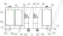
图1为本实用新型的主视结构示意图;Fig. 1 is the main view structure schematic diagram of the utility model;
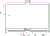
图2为本实用新型的剖视结构示意图;Fig. 2 is the sectional structure schematic diagram of the utility model;
图3为本实用新型的纵向剖视结构示意图;Fig. 3 is the longitudinal sectional structure schematic diagram of the utility model;
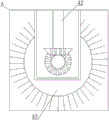
图4为本实用新型图2的A处放大结构示意图。Fig. 4 is a schematic diagram of the enlarged structure at A in Fig. 2 of the present invention.
图中:1、移动结构;11、把手;12、外壳;13、轮毂;14、电机一;15、保护壳;16、蜗杆一;17、蜗杆二;18、支撑架;2、除锈液喷洒结构;21、除锈液储存仓;22、除锈液喷洒管;23、除锈液喷洒泵;24、除锈液喷头;3、除锈结构;31、电机二;32、齿轮杆一;33、打磨刷;34、固定杆;4、抛光结构;41、电机三;42、齿轮杆二;43、抛光刷;5、吸尘结构;51、储尘仓;52、除尘管;53、吸尘器;54、吸尘头;6、喷漆结构;61、油漆仓;62、油漆喷洒管;63、油漆喷洒泵;64、油漆喷洒头。In the figure: 1. Mobile structure; 11. Handle; 12. Shell; 13. Hub; 14. Motor 1; 15. Protective shell; 16. Worm 1; 17. Worm 2; 18. Support frame; 2. Derusting liquid Spray structure; 21. Rust removal liquid storage bin; 22. Rust removal liquid spray pipe; 23. Rust removal liquid spray pump; 24. Rust removal liquid nozzle; 3. Rust removal structure; 31. Motor two; 32. Gear lever one ;33, grinding brush; 34, fixed rod; 4, polishing structure; 41, motor three; 42, gear rod two; 43, polishing brush; 5, dust suction structure; 51, dust storage bin; 52, dust removal pipe; , Vacuum cleaner; 54, Dust suction head; 6, Paint spray structure; 61, Paint bin; 62, Paint spray pipe; 63, Paint spray pump; 64, Paint spray head.
具体实施方式Detailed ways
下面结合实施例对本实用新型做进一步详细说明:Below in conjunction with embodiment the utility model is described in further detail:
实施例1Example 1
如图1-4所示,本实用新型提供了一种船舶制造中船体除锈装置,包括移动结构1,移动结构1的内部设置有除锈液喷洒结构2,除锈液喷洒结构2的一侧设置有除锈结构3,除锈结构3的一侧设置有抛光结构4,抛光结构4的一侧设置有吸尘结构5,吸尘结构5的一侧设置有喷漆结构6;除锈液喷洒结构2包括除锈液储存仓21和除锈液喷洒管22,除锈液储存仓21的底部与除锈液喷洒管22的顶部固定连接,除锈液喷洒管22的表面固定连接有除锈液喷洒泵23;除锈液喷洒管22的一端固定连接有除锈液喷头24,除锈液喷头24的顶部与把手11的底部固定连接。As shown in Figures 1-4, the utility model provides a hull derusting device in shipbuilding, including a mobile structure 1, a derusting liquid spraying structure 2 is arranged inside the mobile structure 1, and a part of the derusting liquid spraying structure 2 The
在本实施例中,通过除锈液喷洒泵23的作用下,将除锈液沿除锈液喷洒管22从除锈液储存仓21中抽出,通过除锈液喷头24喷出,经过除锈液喷头24底部设置的小孔中喷出,除锈液喷出为水雾状,使除锈液喷洒更加均匀。In this embodiment, under the action of the derusting
实施例2Example 2
如图1-4所示,在实施例1的基础上,本实用新型提供一种技术方案:优选的,移动结构1包括把手11和外壳12,把手11的一端与外壳12的表面固定连接,外壳12的底部固定连接有保护壳15,保护壳15内腔的一侧固定连接有电机一14,电机一14转轴的一端啮合有蜗杆一16,蜗杆一16的表面啮合有蜗杆二17,蜗杆二17的两端固定连接有轮毂13,外壳12的底部固定连接有支撑架18,支撑架18的内部与蜗杆二17的表面转动连接,除锈结构3包括电机二31和齿轮杆一32,电机二31转轴的表面与齿轮杆一32的一端啮合,齿轮杆一32一端的表面啮合有打磨刷33,齿轮杆一32的表面转动连接有固定杆34,抛光结构4包括电机三41和齿轮杆二42,电机三41转轴的表面与齿轮杆二42的一端啮合,齿轮杆二42一端的表面啮合有抛光刷43。As shown in Figures 1-4, on the basis of Embodiment 1, the utility model provides a technical solution: preferably, the mobile structure 1 includes a
在本实施例中,通过电机一14转轴的转动时蜗杆一16进行旋转,同时蜗杆一16带动蜗杆二17进行旋转,蜗杆二17带动轮毂13转动使装置移动,装置前两轮为万向轮,可对前进方向进行控制,同时除锈结构3进行除锈后,抛光结构4在对船舶表面进行抛光时也可对船舶表面进行进一步除锈,使除锈效果更好,解决了现有船舶除锈装置为手推式除锈,除锈效果较为不好,同时,由于除锈装置较重,连续的长时间除锈工作会使工人感到疲劳,从而影响工作效率的问题。In this embodiment, the
实施例3Example 3
如图1-4所示,在实施例1的基础上,本实用新型提供一种技术方案:优选的,吸尘结构5包括储尘仓51和除尘管52,储尘仓51的一侧与除尘管52的一端固定连接,除尘管52一端的表面固定连接有吸尘器53,除尘管52的一端固定连接有吸尘头54,吸尘头54的顶部与外壳12的底部固定连接,喷漆结构6包括油漆仓61和油漆喷洒管62,油漆仓61的底部与油漆喷洒管62的顶部固定连接,油漆喷洒管62的表面固定连接有油漆喷洒泵63,油漆喷洒管62的底部固定连接有油漆喷洒头64,油漆喷洒头64的顶部与外壳12的底部固定连接。As shown in Figures 1-4, on the basis of Embodiment 1, the utility model provides a technical solution: preferably, the dust collection structure 5 includes a
在本实施例中,通过除锈液喷洒结构2对船舶表面进行喷洒除锈液,然后除锈结构3对船舶表面进行除锈工作,随后抛光结构4对船舶表面进行抛光的同时,进一步进行除锈,随后通过吸尘结构5将打磨下的锈进行收集,最后由喷漆结构6对船舶表面进行喷漆防锈工作,将船舶除锈工作的步骤进行了减少,解决了在对船舶表面进行除锈后还需分别对船舶表面进行打磨、清洗、喷漆等工序,现有除锈装置功能单一,使船舶除锈工作步骤繁琐,浪费了大量人力物力的问题。In this embodiment, the derusting liquid is sprayed on the surface of the ship through the derusting liquid spraying structure 2, and then the
下面具体说一下该船舶制造中船体除锈装置的工作原理。Let's talk about the working principle of the hull derusting device in the shipbuilding below.
如图1-4所示,在使用本装置时,首先通过除锈液储存仓21和油漆仓顶部设置的加料口分别添加油漆和除锈液,随后,启动电机一14,在电机一14转轴的转动下,带动蜗杆一16进行旋转,同时,蜗杆一16转动带动与其啮合的蜗杆二17转动,蜗杆二17转动带动蜗杆二17两端固定连接的轮毂13转动,使装置可以移动,装置前两个轮毂为万向轮,可对装置的前进方向进行控制,当装置移动至待除锈区域后,启动除锈液喷洒泵23,在除锈液喷洒泵23的作用下,除锈液通过除锈液喷头24被喷洒至船舶表面,随后电机二31转轴的转动使与其啮合的齿轮杆一32转动,同时齿轮杆一32带动与其一端啮合地打磨刷33进行旋转,打磨刷33旋转对船舶表面进行打磨除锈,随后电机三41转轴的转动带动与其啮合的齿轮杆二42转动,齿轮杆二42带动与其一端表面啮合的抛光刷43转动,抛光刷43转动对船舶进行抛光的同时对船舶进行进一步除锈,打磨下的锈在吸尘器53的作用下,从吸尘头54沿除尘管52被吸入至储尘仓内,随后油漆喷洒泵63启动,在油漆喷洒泵63的作用下油漆从油漆仓内被吸出,经过油漆喷洒头64被喷洒至抛光后的船舶表面,使船舶不易生锈。As shown in Figure 1-4, when using this device, at first add paint and derusting liquid respectively through the feeding port that is provided with at the top of the derusting
上文一般性的对本实用新型做了详尽的描述,但在本实用新型基础上,可以对之做一些修改或改进,这对于技术领域的一般技术人员是显而易见的。因此,在不脱离本实用新型思想精神的修改或改进,均在本实用新型的保护范围之内。The above has generally described the utility model in detail, but on the basis of the utility model, some modifications or improvements can be made to it, which is obvious to those skilled in the art. Therefore, any modification or improvement that does not depart from the spirit of the present utility model is within the protection scope of the present utility model.
Claims (7)
Priority Applications (1)
| Application Number | Priority Date | Filing Date | Title |
|---|---|---|---|
| CN202320098265.4U CN219131867U (en) | 2023-02-01 | 2023-02-01 | Hull derusting device in shipbuilding |
Applications Claiming Priority (1)
| Application Number | Priority Date | Filing Date | Title |
|---|---|---|---|
| CN202320098265.4U CN219131867U (en) | 2023-02-01 | 2023-02-01 | Hull derusting device in shipbuilding |
Publications (1)
| Publication Number | Publication Date |
|---|---|
| CN219131867U true CN219131867U (en) | 2023-06-06 |
Family
ID=86599284
Family Applications (1)
| Application Number | Title | Priority Date | Filing Date |
|---|---|---|---|
| CN202320098265.4U Expired - Fee Related CN219131867U (en) | 2023-02-01 | 2023-02-01 | Hull derusting device in shipbuilding |
Country Status (1)
| Country | Link |
|---|---|
| CN (1) | CN219131867U (en) |
-
2023
- 2023-02-01 CN CN202320098265.4U patent/CN219131867U/en not_active Expired - Fee Related
Similar Documents
| Publication | Publication Date | Title |
|---|---|---|
| CN204306751U (en) | Crawler type cleaning machine | |
| CN102085907A (en) | Cabin cleaning robot | |
| CN213287765U (en) | Surface cleaning device is used in round steel production | |
| CN215948034U (en) | Civil engineering operation cleans dust collector | |
| CN214138889U (en) | Semi-automatic rust removing and cleaning device for ship and ocean engineering | |
| JP3233401U (en) | Cleaning equipment for environmental protection equipment | |
| CN110587446A (en) | Steel pipe rust removing device | |
| CN117300850A (en) | A hull rust removal device for shipbuilding | |
| CN222032259U (en) | An environmentally friendly cleaning device for industrial engineering floors | |
| CN213061845U (en) | Road surface scavenging machine is used in road construction | |
| CN219052204U (en) | Highway concrete retaining wall cleaning machine | |
| CN116639225B (en) | Hull microorganism adheres to and clears away collection device | |
| CN110080141A (en) | A kind of cleaning equipment for road stake | |
| CN216259772U (en) | Rotary industrial dust remover | |
| CN212801357U (en) | Cleaning device for electric new energy sanitation truck | |
| CN116512024A (en) | Multidirectional wax spraying equipment for surface of tin-phosphorus bronze wire | |
| CN207306626U (en) | The floor-cleaning machine of wheeled | |
| CN212664442U (en) | Cosmetics production jar outer wall cleaner convenient to adjust | |
| CN210712698U (en) | A cleaning and dust removal device for civil engineering operations | |
| CN220408247U (en) | Rust removal equipment with sewage recovery unit | |
| CN116765054A (en) | Inner and outer synchronous rust removal device based on metal pipeline recovery and rust removal method thereof | |
| CN212527272U (en) | Boats and ships deck dolly of polishing with clean function | |
| CN211465899U (en) | A rust removal device for the outer surface of a water conservancy construction pipeline | |
| CN221046699U (en) | Crawler-type supporter cleaning device | |
| CN222572506U (en) | Wall climbing cleaning robot |
Legal Events
| Date | Code | Title | Description |
|---|---|---|---|
| GR01 | Patent grant | ||
| GR01 | Patent grant | ||
| CF01 | Termination of patent right due to non-payment of annual fee | ||
| CF01 | Termination of patent right due to non-payment of annual fee |
Granted publication date: 20230606 |