JP3233401U - Cleaning equipment for environmental protection equipment - Google Patents
Cleaning equipment for environmental protection equipment Download PDFInfo
- Publication number
- JP3233401U JP3233401U JP2020600134U JP2020600134U JP3233401U JP 3233401 U JP3233401 U JP 3233401U JP 2020600134 U JP2020600134 U JP 2020600134U JP 2020600134 U JP2020600134 U JP 2020600134U JP 3233401 U JP3233401 U JP 3233401U
- Authority
- JP
- Japan
- Prior art keywords
- environmental protection
- protection equipment
- fountain
- cleaning device
- linear slide
- Prior art date
- Legal status (The legal status is an assumption and is not a legal conclusion. Google has not performed a legal analysis and makes no representation as to the accuracy of the status listed.)
- Active
Links
- 238000004140 cleaning Methods 0.000 title claims abstract description 47
- 230000007613 environmental effect Effects 0.000 title claims abstract description 28
- XLYOFNOQVPJJNP-UHFFFAOYSA-N water Substances O XLYOFNOQVPJJNP-UHFFFAOYSA-N 0.000 claims abstract description 70
- 230000001681 protective effect Effects 0.000 claims abstract description 16
- 230000005540 biological transmission Effects 0.000 claims description 20
- 229920000742 Cotton Polymers 0.000 claims description 15
- 238000010521 absorption reaction Methods 0.000 claims description 14
- 239000007788 liquid Substances 0.000 claims description 14
- 238000002347 injection Methods 0.000 claims description 8
- 239000007924 injection Substances 0.000 claims description 8
- 239000000428 dust Substances 0.000 abstract description 7
- 238000010586 diagram Methods 0.000 abstract description 5
- 230000000694 effects Effects 0.000 description 2
- 239000004744 fabric Substances 0.000 description 2
- 230000004308 accommodation Effects 0.000 description 1
- 238000009825 accumulation Methods 0.000 description 1
- 230000009286 beneficial effect Effects 0.000 description 1
- 238000000034 method Methods 0.000 description 1
Images


Classifications
-
- B—PERFORMING OPERATIONS; TRANSPORTING
- B08—CLEANING
- B08B—CLEANING IN GENERAL; PREVENTION OF FOULING IN GENERAL
- B08B3/00—Cleaning by methods involving the use or presence of liquid or steam
- B08B3/02—Cleaning by the force of jets or sprays
- B08B3/024—Cleaning by means of spray elements moving over the surface to be cleaned
-
- B—PERFORMING OPERATIONS; TRANSPORTING
- B08—CLEANING
- B08B—CLEANING IN GENERAL; PREVENTION OF FOULING IN GENERAL
- B08B1/00—Cleaning by methods involving the use of tools
- B08B1/30—Cleaning by methods involving the use of tools by movement of cleaning members over a surface
Landscapes
- Cleaning By Liquid Or Steam (AREA)
Abstract
【課題】除塵掃除および水の拭き取りを容易にする環境保護設備の清潔装置を提供する。【解決手段】環境保護設備の清潔装置は、溜水ケース1、支持フレーム9、直線状滑り台10、およびスライダを含み、溜水ケースの上面に支持フレームが着脱可能に接続されており、支持フレームの内部に直線状滑り台が固定的に接続されており、直線状滑り台の表面にスライダが摺動可能に接続されており、スライダの一側に噴出ユニット8が取付けられており、噴出ユニットは噴水管、高圧ノズル、保護カバーおよび案内輪をそれぞれ含み、噴水管の噴水端に高圧ノズルが連通接続されており、噴水管の噴水端の外部に保護カバーが取付けられており、保護カバーの上面に案内輪が回動接続されており、スライダの他側に拭取ユニット7が取付けられている。直線状滑り台は噴水管を駆動して縦方向に往復動作を行わせ、板体外壁に対して噴出動作を行なって洗浄処理をする。【選択図】図1PROBLEM TO BE SOLVED: To provide a cleaning device for environmental protection equipment which facilitates dust removal cleaning and wiping of water. A cleaning device for environmental protection equipment includes a water storage case 1, a support frame 9, a linear slide 10, and a slider, and a support frame is detachably connected to an upper surface of the water storage case. A linear slide is fixedly connected to the inside of the, a slider is slidably connected to the surface of the linear slide, a ejection unit 8 is attached to one side of the slider, and the ejection unit is a fountain. It includes a pipe, a high-pressure nozzle, a protective cover and a guide ring, respectively. The guide wheels are rotatably connected, and the wiping unit 7 is attached to the other side of the slider. The linear slide drives the fountain pipe to reciprocate in the vertical direction, and ejects the outer wall of the plate to clean it. [Selection diagram] Fig. 1
Description
本実用新案は環境保護設備の補助装置の技術分野に関するもので、具体的には、環境保
護設備の清潔装置に関する。
This utility model relates to the technical field of auxiliary equipment for environmental protection equipment, and specifically to clean equipment for environmental protection equipment.
環境保護設備は、ノイズ減滅機能付ものや、掃除機能付もの、節水節電機能付ものなどが
あげられる。そのうち、道の両側に防音板を配して、騒音を効果的に低減するような手法
も利用されている。これによって、近所の住民やモールに住みやすい宿泊とショッピング
環境を提供する。
Environmental protection equipment includes those with a noise reduction function, those with a cleaning function, and those with a water-saving and power-saving function. Among them, a method of effectively reducing noise by arranging soundproof boards on both sides of the road is also used. This will provide a comfortable accommodation and shopping environment for local residents and malls.
ところが、従来の環境保護設備の清潔装置は以下の欠点を有する。
・防音板は道の両側に配されるもので、多くは雨の日に、雨によって自動的に洗い流し、
除塵掃除を行うことにしている。しかし、干ばつ地域の場合、防音板表面に大量のほこり
が溜まる。このようであると、都市のイメージを壊し、住民の不快感を引き起こす。ほこ
りを一掃するために、清掃人によって拭き取る必要があり、この場合、手間がかかり、仕
事量が大きい。
・拭取り後、水が防音板の表面に残ることがある。清潔布などによって別途で拭き干す必
要があり、手間がかかる。
However, the conventional cleaning device for environmental protection equipment has the following drawbacks.
-Soundproof boards are placed on both sides of the road, and many are automatically washed away by rain on rainy days.
I'm going to do dust removal cleaning. However, in drought areas, a large amount of dust collects on the surface of the soundproof board. If this is the case, it will destroy the image of the city and cause discomfort to the residents. In order to wipe out the dust, it needs to be wiped off by a cleaner, which is laborious and labor intensive.
-After wiping, water may remain on the surface of the soundproof plate. It is necessary to wipe it off separately with a clean cloth, which is troublesome.
本実用新案の目的は、背景の技術に記載のように、従来の環境保護設備の清潔装置では、
防音板は道の両側に配されるもので、多くは雨の日に、雨によって自動的に洗い流し、除
塵掃除を行うことにしているが、干ばつ地域の場合、防音板表面に大量のほこりが溜まり
、このようであると、都市のイメージを壊し、住民の不快感を引き起こすことがあり、ほ
こりを一掃するために、清掃人によって拭き取る必要があり、この場合、手間がかかり、
仕事量が大きい、また拭取後、防音板の表面に水が残ることがあり、清潔布などによって
別途で拭き干す必要があり、手間がかかる、という欠点を克服できる環境保護設備の清潔
装置を提供することにある。
As described in the background technology, the purpose of this utility model is to use conventional cleaning equipment for environmental protection equipment.
Soundproof boards are placed on both sides of the road, and on rainy days, they are automatically washed away by rain to remove dust, but in drought areas, a large amount of dust is collected on the surface of the soundproof board. Accumulation, which can destroy the image of the city and cause discomfort to the inhabitants and must be wiped off by a cleaner to clear the dust, in this case laborious and laborious.
A cleaning device for environmental protection equipment that can overcome the drawbacks of heavy work, water may remain on the surface of the soundproof plate after wiping, and it is necessary to wipe it off separately with a clean cloth, which is troublesome. To provide.
上記の目のを実現するために、本実用新案は、下記の環境保護設備の清潔装置を提供する
。該環境保護設備の清潔装置は、 溜水ケース、支持フレーム、直線状滑り台、およびス
ライダを含み、前記溜水ケースの上面に支持フレームが着脱可能に接続されており、前記
支持フレームの内部に直線状滑り台が固定的に接続されており、前記直線状滑り台の表面
にスライダが摺動可能に接続されており、前記スライダの一側に噴出ユニットが取付けら
れており、前記噴出ユニットは噴水管、高圧ノズル、保護カバーおよび案内輪をそれぞれ
含み、前記噴水管の噴水端に高圧ノズルが連通接続されており、前記噴水管の噴水端の外
部に保護カバーが取付けられており、前記保護カバーの上面に案内輪が回動接続されてお
り、前記スライダの他側に拭取ユニットが取付けられている。直線状滑り台の両側にそれ
ぞれ噴出ユニットおよび拭取ユニットが取付けられる。直線状滑り台によって噴出ユニッ
トを縦方向に摺動させるように駆動する。板体の表面に対して自動的に噴出洗浄を行う。
洗浄後、溜水ケースを回して、直線状滑り台により拭取ユニットを駆動して板体の外壁を
拭いて干させる。これにより水の残りを減少でき、洗浄と拭き干し機能を一体化させて、
工人労働の強度を低減する。
In order to realize the above eyes, this utility model provides the following environmental protection equipment cleaning equipment. The cleaning device of the environmental protection equipment includes a water storage case, a support frame, a linear slide, and a slider, and the support frame is detachably connected to the upper surface of the water storage case and is straight inside the support frame. The shape slide is fixedly connected, the slider is slidably connected to the surface of the linear slide, the ejection unit is attached to one side of the slider, and the ejection unit is a fountain pipe. A high-pressure nozzle, a protective cover, and a guide ring are included, respectively, a high-pressure nozzle is continuously connected to the fountain end of the fountain pipe, and a protective cover is attached to the outside of the fountain end of the fountain pipe. A guide wheel is rotatably connected to the slider, and a wiping unit is attached to the other side of the slider. A ejection unit and a wiping unit are attached to both sides of the linear slide, respectively. A linear slide drives the ejection unit to slide in the vertical direction. Automatically ejects and cleans the surface of the plate.
After cleaning, the water collecting case is turned and the wiping unit is driven by a linear slide to wipe the outer wall of the plate and dry it. This reduces the amount of water left over, integrating cleaning and wiping functions.
Reduce the intensity of worker labor.
好ましくは、前記溜水ケースの側壁における頂端寄りの位置に注水管が連通接続されてお
り、前記溜水ケースの上面に洗浄液保存タンクが挿抜可能に接続されている。注水管によ
って溜水ケース内に容易に水を注入することができる。これにより水の供給を充分に確保
することができる。洗浄液保存タンク内に洗浄液を保存することにより、タンクを押出す
ると、水内へ洗浄液を添加することができ、洗浄効果を高められる。
Preferably, the water injection pipe is connected to the side wall of the water storage case near the top end, and the cleaning liquid storage tank is connected to the upper surface of the water storage case so that it can be inserted and removed. Water can be easily injected into the reservoir case by the water injection pipe. As a result, a sufficient supply of water can be secured. By storing the cleaning liquid in the cleaning liquid storage tank, when the tank is extruded, the cleaning liquid can be added into the water and the cleaning effect can be enhanced.
好ましくは、前記溜水ケースの底端に自在キャスターが固定的に接続されており、前記自
在キャスターの一側にブレーキプレートが移動可能に接続されている。溜水ケースの底端
に自在キャスターが固定的に接続されるように構成されると、自在キャスターによって容
易に溜水ケースを押し引きすることができ、溜水ケースを移動することが容易になって、
省力的にできる。
Preferably, the universal casters are fixedly connected to the bottom end of the water storage case, and the brake plate is movably connected to one side of the flexible casters. If the universal casters are fixedly connected to the bottom end of the reservoir case, the flexible casters can easily push and pull the reservoir case, making it easy to move the reservoir case. hand,
It can be labor-saving.
好ましくは、前記拭取ユニットはサーボモータ、変速機および綿付ローラーをそれぞれ含
む。
Preferably, the wiping unit includes a servomotor, a transmission and a cotton roller, respectively.
好ましくは、前記サーボモータの伝動出力端は変速機によって綿付ローラーに伝動的に接
続されている。サーボモータに電源を投入すると、サーボモータは変速機により綿付ロー
ラー703を回動駆動させる。直線状滑り台により拭取ユニットを駆動して縦方向往復動
作を行わせる。これにより板体外壁に残った液を拭取って清潔処理をする。
Preferably, the transmission output end of the servomotor is conductively connected to the cotton roller by a transmission. When the power is turned on to the servomotor, the servomotor rotates and drives the
好ましくは、前記溜水ケースの表面に吸水管が插接されている。 Preferably, the water absorption pipe is rubbed on the surface of the water storage case.
好ましくは、前記吸水管とポンプの吸水端とが連通接続されている。 Preferably, the water absorption pipe and the water absorption end of the pump are communicated with each other.
好ましくは、前記ポンプの噴水端は波紋チューブによって噴水管に連通接続されている。
ポンプおよび吸水管によって溜水ケース内の水を加圧する。水は波紋チューブを通して噴
水管内に流れ込み、高圧ノズルから噴出する。直線状滑り台によって噴水管を駆動して縦
方向に往復動作を行わせる。これにより板体外壁に対して噴出動作を行なって洗浄処理を
する。保護カバーによって水の飛び散らすことを防止する。案内輪が板体外壁に貼りつく
ことで、噴水管の縦方向摺動を容易にさせる。
Preferably, the fountain end of the pump is communicated with the fountain pipe by a ripple tube.
The water in the reservoir case is pressurized by the pump and the water absorption pipe. Water flows into the fountain tube through the ripple tube and is ejected from the high pressure nozzle. The fountain pipe is driven by a linear slide to reciprocate in the vertical direction. As a result, the outer wall of the plate body is ejected to perform cleaning treatment. The protective cover prevents water from splashing. The guide ring sticks to the outer wall of the plate body, which facilitates the vertical sliding of the fountain pipe.
好ましくは、前記支持フレームの頂端に太陽電池パネル、蓄電池およびインバータがそれ
ぞれ取付けられている。前記太陽電池パネルの電気出力端はインバータによって蓄電池に
電気接続されている。
Preferably, a solar cell panel, a storage battery and an inverter are attached to the top ends of the support frame. The electric output end of the solar cell panel is electrically connected to the storage battery by an inverter.
好ましくは、前記溜水ケースの側壁にコントロールパネルが取付けられており、前記蓄電
池はコントロールパネル、ポンプ、サーボモータおよび直線状滑り台にそれぞれ電気接続
されている。これによって、洗浄および拭取仕事はいずれもユーザ側で行う。また太陽電
池パネルとインバータの組み合わせで、蓄電池内で電気エネルギーを蓄電し、各電気に電
力を供給する。
Preferably, a control panel is attached to the side wall of the water storage case, and the storage battery is electrically connected to the control panel, the pump, the servomotor, and the linear slide, respectively. As a result, both cleaning and wiping work are performed by the user. In addition, the combination of a solar panel and an inverter stores electric energy in the storage battery and supplies electric power to each electric power.
従来の技術と比べて、本実用新案の有益な効果は以下の通りである。 Compared with the conventional technology, the beneficial effects of this utility model are as follows.
(1)本実用新案では、支持フレーム内に直線状滑り台が固定的に接続され、直線状滑り
台の表面にスライダが摺動可能に接続され、スライダの一側に噴出ユニットがが取付けら
れており、噴出ユニットは噴水管、高圧ノズル、保護カバーおよび案内輪をそれぞれ備え
る。ポンプおよび吸水管によって溜水ケース内の水を加圧する。水は波紋チューブを通し
て噴水管内に流れ込み、高圧ノズルから噴出する。直線状滑り台は噴水管を駆動して縦方
向に往復動作を行わせる。これにより板体外壁に対して噴出動作を行なって洗浄処理をす
る。保護カバーによって水の飛び散らすことを防止する。案内輪が板体外壁に貼りつくこ
とで、噴水管の縦方向摺動を容易にさせる。
(1) In this utility model, a linear slide is fixedly connected in the support frame, a slider is slidably connected to the surface of the linear slide, and a ejection unit is attached to one side of the slider. , The ejection unit is provided with a fountain pipe, a high pressure nozzle, a protective cover and a guide ring, respectively. The water in the reservoir case is pressurized by the pump and the water absorption pipe. Water flows into the fountain tube through the ripple tube and is ejected from the high pressure nozzle. The linear slide drives the fountain pipe to reciprocate in the vertical direction. As a result, the outer wall of the plate body is ejected to perform cleaning treatment. The protective cover prevents water from splashing. The guide ring sticks to the outer wall of the plate body, which facilitates the vertical sliding of the fountain pipe.
(2)本実用新案では、スライダの他側に拭取ユニットが取付けられ、拭取ユニットはサ
ーボモータ、変速機および綿付ローラーをそれぞれ含む。サーボモータの伝動出力端は変
速機を介して綿付ローラーに伝動可能に接続される。サーボモータに電源を投入すると、
サーボモータは変速機により綿付ローラーを回動駆動させる。直線状滑り台により拭取ユ
ニットを駆動して縦方向往復動作を行わせる。これにより板体外壁に残った液を拭取って
清潔処理をする。
(2) In this utility model, a wiping unit is attached to the other side of the slider, and the wiping unit includes a servomotor, a transmission, and a roller with cotton, respectively. The transmission output end of the servomotor is migably connected to the cotton roller via the transmission. When the power is turned on to the servo motor,
The servomotor rotates and drives the cotton roller with a transmission. The wiping unit is driven by a linear slide to perform vertical reciprocating operation. As a result, the liquid remaining on the outer wall of the plate is wiped off and cleaned.
図1〜4に示されるように、本実用新案は環境保護設備の清潔装置を提供する。該環境保
護設備の清潔装置は、溜水ケース1、支持フレーム9、直線状滑り台10、およびスライ
ダ1001を含み、前記溜水ケース1の上面に支持フレーム9が着脱可能に接続されてお
り、前記支持フレーム9の内部に直線状滑り台10が固定的に接続されており、前記直線
状滑り台10の表面にスライダ1001が摺動可能に接続されており、前記スライダ10
01の一側に噴出ユニット8が取付けられており、前記噴出ユニット8は噴水管801、
高圧ノズル802、保護カバー803および案内輪804をそれぞれ含み、前記噴水管8
01の噴水端に高圧ノズル802が連通接続されており、前記噴水管801の噴水端の外
部に保護カバー803が取付けられており、前記保護カバー803の上面に案内輪804
が回動接続されており、前記スライダ1001の他側に拭取ユニット7が取付けられてい
る。
As shown in FIGS. 1 to 4, this utility model provides a cleaning device for environmental protection equipment. The cleaning device of the environmental protection equipment includes a
An
The
A high-
Is rotatably connected, and the
前記溜水ケース1の側壁における頂端寄りの位置に注水管101が連通接続されており、
前記溜水ケース1の上面に洗浄液保存タンク6が挿抜可能に接続されている。注水管10
1によって容易に溜水ケース1内に水を注入することができる。これにより水の供給を充
分に確保することができる。洗浄液保存タンク6内に洗浄液を保存することにより、タン
クを押出すると、水内へ洗浄液を添加することができ、洗浄効果を高める。
A
A cleaning liquid storage tank 6 is removably connected to the upper surface of the
Water can be easily injected into the
前記溜水ケース1の底端に自在キャスター2が固定的に接続されており、前記自在キャス
ター2の一側にブレーキプレート201が移動可能に接続されている。溜水ケース1の底
端に自在キャスター2が固定的に接続されるように構成されると、自在キャスター2によ
って容易に溜水ケース1を押し引きすることができ、ケースを移動させることが容易にな
り、省力的にできる。
The
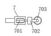
前記拭取ユニット7はサーボモータ701、変速機702および綿付ローラー703をそ
れぞれ含む。
The
前記サーボモータ701の伝動出力端は変速機702によって綿付ローラー703に伝動
的に接続されている。サーボモータ701に電源を投入すると、サーボモータ701は変
速機702により綿付ローラー703を回動駆動させる。直線状滑り台10により拭取ユ
ニット7を駆動して縦方向往復動作を行わせる。これにより板体外壁に残った液を拭取っ
て清潔処理をする。
The transmission output end of the
前記溜水ケース1の表面に吸水管3が插接されている。
The water absorption pipe 3 is rubbed against the surface of the
前記吸水管3とポンプ4の吸水端とが連通接続されている。 The water absorption pipe 3 and the water absorption end of the pump 4 are communicated with each other.
前記ポンプ4の噴水端は波紋チューブ401によって噴水管801に連通接続されている
。ポンプ4および吸水管3によって溜水ケース1内の水を加圧する。水は波紋チューブ4
01を通して噴水管801内に流れ込み、高圧ノズル802から噴出する。直線状滑り台
10は噴水管801を駆動して縦方向に往復動作を行わせる。これにより板体外壁に対し
噴出動作をおこなって洗浄処理をする。保護カバー803によって水の飛びを防止する。
案内輪804が板体外壁に貼り付けて、噴水管801の縦方向摺動を容易にさせる。
The fountain end of the pump 4 is communicated with the
It flows into the
The
前記支持フレーム9の頂端に太陽電池パネル11、蓄電池12およびインバータ13がそ
れぞれ取付けられている。前記太陽電池パネル11の電気出力端はインバータ13によっ
て蓄電池12に電気接続されている。
A
前記溜水ケース1の側壁にコントロールパネル5が取付けられており、前記蓄電池12は
コントロールパネル5、ポンプ4、サーボモータ701および直線状滑り台10にそれぞ
れ電気接続されている。洗浄および拭取仕事はいずれもユーザ側で行う。また太陽電池パ
ネル11とインバータ13の組み合わせで、蓄電池12内で電気エネルギーを蓄電し、各
電気に電力を供給する。
A
本考案の環境保護設備の清潔装置の動作に関しては、下記のとおり特筆すべきである。
溜水ケース1の上面に支持フレーム9が着脱可能に接続され、支持フレーム9内に直線状
滑り台10が固定的に接続され、直線状滑り台10の表面にスライダ1001が摺動可能
に接続され、スライダ1001の一側に噴出ユニット8がが取付けられており、噴出ユニ
ット8は噴水管801、高圧ノズル802、保護カバー803および案内輪804をそれ
ぞれ備える。ポンプ4および吸水管3によって溜水ケース1内の水を加圧する。水は波紋
チューブ401を通して噴水管801内に流れ込み、高圧ノズル802から噴出する。直
線状滑り台10は噴水管801を駆動して縦方向に往復動作を行わせる。これにより板体
外壁に噴出動作をして洗浄処理をする。保護カバー803によって水の飛び散らしを防止
する。案内輪804が板体外壁に貼り付けて、噴水管801を縦方向摺動に容易にさせる
。スライダ1001の他側に拭取ユニット7が取付けられている。拭取ユニット7はサー
ボモータ701、変速機702および綿付ローラー703をそれぞれ含み、サーボモータ
701の伝動出力端は変速機702によって綿付ローラー703に伝動可能に接続される
。サーボモータ701に電源を投入すると、サーボモータ701は変速機702により綿
付ローラー703を回動駆動させる。直線状滑り台10により拭取ユニット7を駆動して
縦方向往復動作を行わせる。これにより板体外壁に残った液を拭取して清潔処理をする。
ここで、インバータ13の番型はSUS−500Aとする。
Regarding the operation of the cleaning device of the environmental protection equipment of the present invention, it should be noted as follows.
A
Here, the model number of the
1 溜水ケース
101 注水管
2 自在キャスター
201 ブレーキプレート
3 吸水管
4 ポンプ
401 波紋チューブ
5 コントロールパネル
6 洗浄液保存タンク
7 拭取ユニット
701 サーボモータ
702 変速機
703 綿付ローラー
8 噴出ユニット
801 噴水管
802 高圧ノズル
803 保護カバー
804 案内輪
9 支持フレーム
10 直線状滑り台
1001 スライダ
11 太陽電池パネル
12 蓄電池
13 インバータ
1
Claims (10)
001)を含み、前記溜水ケース(1)の上面に支持フレーム(9)が着脱可能に接続さ
れており、前記支持フレーム(9)の内部に直線状滑り台(10)が固定的に接続されて
おり、前記直線状滑り台(10)の表面にスライダ(1001)が摺動可能に接続されて
おり、前記スライダ(1001)の一側に噴出ユニット(8)が取付けられており、前記
噴出ユニット(8)は噴水管(801)、高圧ノズル(802)、保護カバー(803)
および案内輪(804)をそれぞれ含み、前記噴水管(801)の噴水端に高圧ノズル(
802)が連通接続されており、前記噴水管(801)の噴水端の外部に保護カバー(8
03)が取付けられており、前記保護カバー(803)の上面に案内輪(804)が回動
接続されており、前記スライダ(1001)の他側に拭取ユニット(7)が取付けられて
いることを特徴とする環境保護設備の清潔装置。 Reservoir case (1), support frame (9), linear slide (10), and slider (1)
001) is included, the support frame (9) is detachably connected to the upper surface of the water storage case (1), and the linear slide (10) is fixedly connected to the inside of the support frame (9). A slider (1001) is slidably connected to the surface of the linear slide (10), and a ejection unit (8) is attached to one side of the slider (1001). (8) is a fountain pipe (801), a high-pressure nozzle (802), and a protective cover (803).
And a high-pressure nozzle (804) at the fountain end of the fountain pipe (801), including a guide wheel (804).
802) is communicated and connected, and a protective cover (8) is provided outside the fountain end of the fountain pipe (801).
03) is attached, the guide ring (804) is rotatably connected to the upper surface of the protective cover (803), and the wiping unit (7) is attached to the other side of the slider (1001). A cleansing device for environmental protection equipment.
ており、前記溜水ケース(1)の上面に洗浄液保存タンク(6)が挿抜可能に接続されて
いることを特徴とする請求項1に記載の環境保護設備の清潔装置。 A water injection pipe (101) is connected to the side wall of the water storage case (1) near the top end, and a cleaning liquid storage tank (6) is connectable to the upper surface of the water storage case (1) so as to be removable. The cleaning device for environmental protection equipment according to claim 1, wherein the device is provided.
自在キャスター(2)の一側にブレーキプレート(201)が移動可能に接続されている
ことを特徴とする請求項1に記載の環境保護設備の清潔装置。 The universal caster (2) is fixedly connected to the bottom end of the water storage case (1), and the brake plate (201) is movably connected to one side of the flexible caster (2). The cleaning device for the environmental protection equipment according to claim 1.
ー(703)をそれぞれ含むことを特徴とする請求項1に記載の環境保護設備の清潔装置
。 The cleaning device for environmental protection equipment according to claim 1, wherein the wiping unit (7) includes a servomotor (701), a transmission (702), and a cotton roller (703), respectively.
03)に伝動的に接続されていることを特徴とする請求項4に記載の環境保護設備の清潔
装置。 The transmission output end of the servo motor (701) is connected to a cotton roller (7) by a transmission (702).
03) The cleaning device for environmental protection equipment according to claim 4, wherein the device is electrically connected.
に記載の環境保護設備の清潔装置。 Claim 1 characterized in that a water absorption pipe (3) is squeezed onto the surface of the water storage case (1).
Cleaning equipment for environmental protection equipment described in.
項6に記載の環境保護設備の清潔装置。 The cleaning device for environmental protection equipment according to claim 6, wherein the water absorption pipe (3) and the water absorption end of the pump (4) are communicated with each other.
続されていることを特徴とする請求項7に記載の環境保護設備の清潔装置。 The cleaning device for environmental protection equipment according to claim 7, wherein the fountain end of the pump (4) is communicated with a fountain pipe (801) by a ripple tube (401).
ータ(13)がそれぞれ取付けられており、前記太陽電池パネル(11)の電気出力端は
インバータ(13)によって蓄電池(12)に電気接続されていることを特徴とする請求
項1に記載の環境保護設備の清潔装置 A solar cell panel (11), a storage battery (12), and an inverter (13) are attached to the top ends of the support frame (9), and the electric output end of the solar cell panel (11) is a storage battery by the inverter (13). The cleaning device for environmental protection equipment according to claim 1, wherein the device is electrically connected to (12).
池(12)はコントロールパネル(5)、ポンプ(4)、サーボモータ(701)と直線
状滑り台(10)にそれぞれ電気接続されていることを特徴とする請求項1に記載の環境
保護設備の清潔装置。 A control panel (5) is attached to the side wall of the water storage case (1), and the storage battery (12) includes a control panel (5), a pump (4), a servomotor (701), and a linear slide (10). The cleaning device for environmental protection equipment according to claim 1, wherein each of them is electrically connected to the above.
Applications Claiming Priority (3)
| Application Number | Priority Date | Filing Date | Title |
|---|---|---|---|
| CN202021534261.9U CN212883804U (en) | 2020-07-29 | 2020-07-29 | Environmental protection equipment cleaning device |
| CN202021534261.9 | 2020-07-29 | ||
| PCT/CN2020/105952 WO2020228849A2 (en) | 2020-07-29 | 2020-07-30 | Environmenally friendly equipment cleaning device |
Publications (1)
| Publication Number | Publication Date |
|---|---|
| JP3233401U true JP3233401U (en) | 2021-08-05 |
Family
ID=73290341
Family Applications (1)
| Application Number | Title | Priority Date | Filing Date |
|---|---|---|---|
| JP2020600134U Active JP3233401U (en) | 2020-07-29 | 2020-07-30 | Cleaning equipment for environmental protection equipment |
Country Status (3)
| Country | Link |
|---|---|
| JP (1) | JP3233401U (en) |
| CN (1) | CN212883804U (en) |
| WO (1) | WO2020228849A2 (en) |
Families Citing this family (2)
| Publication number | Priority date | Publication date | Assignee | Title |
|---|---|---|---|---|
| CN113737197A (en) * | 2021-08-17 | 2021-12-03 | 时旭 | Intelligent high-pressure water spray rust cleaning device for manufacturing high-end equipment |
| CN113751423B (en) * | 2021-08-24 | 2023-08-01 | 国网山东省电力公司淄博供电公司 | Short-distance electrified dust removal equipment for high-voltage transformer equipment |
Family Cites Families (9)
| Publication number | Priority date | Publication date | Assignee | Title |
|---|---|---|---|---|
| JP3692235B2 (en) * | 1998-03-23 | 2005-09-07 | 国土交通省関東地方整備局長 | Translucent sound insulation wall cleaning device |
| JP2005068678A (en) * | 2003-08-20 | 2005-03-17 | Shin Meiwa Ind Co Ltd | Cleaning vehicle |
| CN201395122Y (en) * | 2009-05-12 | 2010-02-03 | 湖南恒润高科有限公司 | Cleaning device of multi-function cleaning vehicle |
| CN207760746U (en) * | 2017-10-27 | 2018-08-24 | 艾立 | Novel insulation board on a kind of expressway |
| CN108517818A (en) * | 2018-03-14 | 2018-09-11 | 合肥银创宏达机器人有限公司 | A kind of cleaning vehicle of road soundproof wall |
| CN208379519U (en) * | 2018-05-17 | 2019-01-15 | 朱江涛 | A kind of soundproof wall cleaning machine |
| CN110184959A (en) * | 2019-06-03 | 2019-08-30 | 江苏鑫瑞交通建设集团有限公司 | A kind of induction rainwater Automatic-cleaning type sound barrier |
| CN110219257A (en) * | 2019-07-15 | 2019-09-10 | 西藏中驰集团股份有限公司 | A kind of cleaning system for sound barrier |
| CN211079953U (en) * | 2019-09-16 | 2020-07-24 | 张敏 | Self-cleaning road noise barrier |
-
2020
- 2020-07-29 CN CN202021534261.9U patent/CN212883804U/en active Active
- 2020-07-30 JP JP2020600134U patent/JP3233401U/en active Active
- 2020-07-30 WO PCT/CN2020/105952 patent/WO2020228849A2/en active Application Filing
Also Published As
| Publication number | Publication date |
|---|---|
| CN212883804U (en) | 2021-04-06 |
| WO2020228849A3 (en) | 2021-06-17 |
| WO2020228849A2 (en) | 2020-11-19 |
Similar Documents
| Publication | Publication Date | Title |
|---|---|---|
| CN102078169B (en) | Floor cleaning robot | |
| CN202015139U (en) | Robot for cleaning floor | |
| CN201001695Y (en) | Electric multifunctional floor mopping vehicle | |
| JP3233401U (en) | Cleaning equipment for environmental protection equipment | |
| CN208301596U (en) | A kind of self-cleaning is swept the floor moping floor integrated machine | |
| CN112871780B (en) | Clean equipment of using of photovoltaic power generation board | |
| CN107080502B (en) | Intelligent cleaning robot system | |
| CN113058888A (en) | Photovoltaic electroplax cleaning device for producing new forms of energy | |
| CN100490721C (en) | Electric window wiper | |
| CN201743628U (en) | Novel automatic wiping steam mop | |
| CN212328996U (en) | Agricultural greenhouse convenient to wash | |
| CN213910067U (en) | Clean floor cleaning robot | |
| CN214022182U (en) | Energy-saving external cleaning device for air conditioner | |
| CN218854977U (en) | Electro-hydraulic hammer cleaning device | |
| CN108994681A (en) | A kind of grinding device of the interior decoration with dust collection function | |
| CN210408274U (en) | Cleaning device | |
| CN210095639U (en) | Belt cleaning device for performance stage | |
| CN218186636U (en) | Step cleaning device | |
| CN2560300Y (en) | Floor cleaning machine | |
| CN215838815U (en) | Multifunctional steam mop | |
| CN201393981Y (en) | Eccentric link rod sliding block cleaning device | |
| CN212612192U (en) | Road surface dust collector is used in road construction | |
| CN212098792U (en) | Trouble-saving and labor-saving multifunctional vehicle wiping device | |
| CN208009337U (en) | A kind of novel environment friendly road cleaner | |
| CN219372377U (en) | Power supply device for motor home |
Legal Events
| Date | Code | Title | Description |
|---|---|---|---|
| R150 | Certificate of patent or registration of utility model |
Ref document number: 3233401 Country of ref document: JP Free format text: JAPANESE INTERMEDIATE CODE: R150 |