CN219010275U - Fodder fermentation equipment capable of improving raw material utilization rate - Google Patents
Fodder fermentation equipment capable of improving raw material utilization rate Download PDFInfo
- Publication number
- CN219010275U CN219010275U CN202223471217.XU CN202223471217U CN219010275U CN 219010275 U CN219010275 U CN 219010275U CN 202223471217 U CN202223471217 U CN 202223471217U CN 219010275 U CN219010275 U CN 219010275U
- Authority
- CN
- China
- Prior art keywords
- groups
- fermentation
- motor
- feed
- raw materials
- Prior art date
- Legal status (The legal status is an assumption and is not a legal conclusion. Google has not performed a legal analysis and makes no representation as to the accuracy of the status listed.)
- Active
Links
Images


Classifications
-
- Y—GENERAL TAGGING OF NEW TECHNOLOGICAL DEVELOPMENTS; GENERAL TAGGING OF CROSS-SECTIONAL TECHNOLOGIES SPANNING OVER SEVERAL SECTIONS OF THE IPC; TECHNICAL SUBJECTS COVERED BY FORMER USPC CROSS-REFERENCE ART COLLECTIONS [XRACs] AND DIGESTS
- Y02—TECHNOLOGIES OR APPLICATIONS FOR MITIGATION OR ADAPTATION AGAINST CLIMATE CHANGE
- Y02P—CLIMATE CHANGE MITIGATION TECHNOLOGIES IN THE PRODUCTION OR PROCESSING OF GOODS
- Y02P60/00—Technologies relating to agriculture, livestock or agroalimentary industries
- Y02P60/80—Food processing, e.g. use of renewable energies or variable speed drives in handling, conveying or stacking
- Y02P60/87—Re-use of by-products of food processing for fodder production
Abstract
The utility model discloses feed fermentation equipment for improving the utilization rate of raw materials, which comprises a supporting bottom plate, a rotating assembly and a stirring assembly, wherein the supporting bottom plate is made of metal materials, a plurality of groups of shock pads are arranged on the supporting bottom plate, and the rotating assembly is arranged at the top end of the supporting bottom plate. According to the utility model, the stirring assembly is arranged, the sealing cover is unscrewed to put the feed raw material into the fermentation barrel, the sealing cover is screwed with the discharge hole after the feeding is finished, the stirring rod and the scraping plate are driven to rotate by the motor II, the feed raw material can be stirred by the rotation of the stirring rod, the temperature in the fermentation barrel can be raised by the flow guide fan and the heating plate, the feed raw material can be prevented from flowing into the heating box by the one-way valve, the fermentation of the feed raw material is facilitated, after the fermentation is finished, the lantern ring is driven to move by the electric push rod, the residual feed on the surface of the stirring rod can be scraped off, the residual feed raw material on the inner wall of the fermentation barrel can be scraped off by the scraping plate, the waste of the feed raw material is avoided, and the utilization rate of the raw material is improved.
Description
Technical Field
The utility model relates to the technical field of feed, in particular to feed fermentation equipment for improving the utilization rate of raw materials.
Background
In the process of livestock and poultry cultivation, in order to ensure the normal growth and nutrition intake of livestock and poultry, the livestock and poultry are fed with feed, and the feed needs to be crushed, fermented and other steps when being treated, and the feed treated by fermentation has the effect of improving the nutrition absorption level of the feed, so that feed fermentation equipment for improving the utilization rate of raw materials is needed.
The prior art has the following defects: when the existing feed fermentation equipment is used for fermenting feed, the raw materials of the feed have certain viscosity, and the raw materials are easy to adhere to the inner wall of a fermentation barrel and the surface of a stirring rod, so that the raw materials are wasted, and the equipment is inconvenient to clean by users;
in the prior art, the feed fermentation equipment disclosed by the publication No. CN218058969U is used for stirring and fermenting the feed raw materials by using a stirring rod, but the feed raw materials are easy to remain on the inner wall of a stirring barrel and the surface of the stirring rod, so that the waste of resources is caused.
Disclosure of Invention
The utility model aims to provide feed fermentation equipment for improving the utilization rate of raw materials so as to solve the problems in the background technology.
In order to achieve the above purpose, the present utility model provides the following technical solutions: the utility model provides an improve fodder fermentation equipment of raw materials utilization ratio, includes supporting baseplate, rotating assembly and stirring subassembly, supporting baseplate is made by metal material, the multiunit shock pad is installed to the supporting baseplate, rotating assembly installs on the supporting baseplate top, stirring subassembly installs on the supporting baseplate top and is located rotating assembly one side.
As a further preferable mode of the technical scheme, two groups of supporting plates are installed on the top end bolts of the supporting bottom plate, and the two groups of supporting plates are symmetrically arranged.
As the further preferred of this technical scheme, rotating assembly includes motor case, motor, transfer line, fermentation vat, auxiliary rod and heating cabinet, the motor case passes through the bolt to be installed in backup pad one side, motor installs in motor incasement No. one, the transfer line is installed at motor output No. one, the fermentation vat is installed in transfer line one end, the auxiliary rod is installed in fermentation vat one side, the heating cabinet is installed on fermentation vat top.
As a further preferred aspect of the present utility model, the auxiliary lever is rotatably connected to the support plate, and the fermenter is made of a heat insulating material.
As the further preferred of this technical scheme, stirring subassembly includes No. two motors, transmission shaft, multiunit puddler, two sets of scrapers, multiunit electric putter, multiunit lantern ring, connecting rod and heating portion, no. two motors are installed at the fermenter inner wall, the transmission shaft is installed No. two motor output, and the multiunit the puddler cover is established and is installed outside the transmission shaft, and two sets of the scraper blade is installed in the transmission shaft both sides, multiunit electric putter installs in the transmission shaft, and the multiunit the lantern ring cover is established and is installed outside the puddler, the connecting rod is installed between the lantern ring, heating portion installs in the heating box.
As the further preferred of this technical scheme, the heating portion includes multiunit water conservancy diversion fan, hot plate, multiunit check valve, discharge gate and sealed lid, multiunit the water conservancy diversion fan passes through the bolt to be installed in the heating cabinet, the hot plate joint is installed in the heating cabinet, multiunit the check valve inlays to be established and is installed between heating cabinet and fermentation vat, the discharge gate is installed in the fermentation vat bottom, sealed lid cover is established and is installed in the discharge gate outside.
As a further preferable mode of the technical scheme, the transmission shaft is rotationally connected with the inner wall of the fermentation barrel, the sealing cover is screwed with the discharge hole through threads, and the electric push rod is connected with the connecting rod.
The utility model provides feed fermentation equipment for improving the utilization rate of raw materials, which has the following beneficial effects:
(1) According to the utility model, the stirring assembly is arranged, the sealing cover is unscrewed to put feed raw materials into the fermentation barrel, the sealing cover is screwed with the discharge hole after the feeding is finished, the transmission shaft is driven to rotate by the motor II, the stirring rod and the scraping plate are driven to rotate by the rotation of the transmission shaft, the feed raw materials can be stirred by the rotation of the stirring rod, the temperature in the fermentation barrel can be raised by the flow guide fan and the heating plate, the feed raw materials can be prevented from flowing into the heating box by the one-way valve, the fermentation of the feed raw materials is facilitated, the connecting rod is driven to move by the electric push rod after the fermentation is finished, the lantern ring is driven to move by the movement of the connecting rod, the feed remained on the surface of the stirring rod can be scraped off, the feed raw materials remained on the inner wall of the fermentation barrel can be scraped off by the scraping plate, the waste of the feed raw materials is avoided, and the utilization rate of the raw materials is improved.
(2) According to the utility model, the rotary assembly is arranged, when the feed raw material is fermented, the first motor is utilized to drive the transmission rod to rotate, and the rotation of the transmission rod drives the fermentation barrel to rotate under the cooperation of the auxiliary rod, so that the full fermentation of the feed raw material in the fermentation barrel is facilitated.
Drawings
FIG. 1 is a schematic diagram of the overall structure of the present utility model;
FIG. 2 is a schematic diagram of a rotary assembly according to the present utility model;
FIG. 3 is a schematic view of a stirring assembly according to the present utility model;
fig. 4 is an enlarged schematic view of the structure of fig. 3 a according to the present utility model.
In the figure: 1. a support base plate; 2. a rotating assembly; 3. a stirring assembly; 4. a support plate; 5. a motor case; 6. a motor I; 7. a transmission rod; 8. a fermentation barrel; 9. an auxiliary lever; 10. a heating box; 11. a motor II; 12. a transmission shaft; 13. a stirring rod; 14. a scraper; 15. an electric push rod; 16. a collar; 17. a connecting rod; 18. a heating section; 19. a guide fan; 20. a heating plate; 21. a one-way valve; 22. a discharge port; 23. sealing cover.
Detailed Description
The technical solutions in the embodiments of the present utility model will be clearly and completely described below with reference to the accompanying drawings in the embodiments of the present utility model.
The utility model provides the technical scheme that: as shown in fig. 1 and 2, in this embodiment, a fodder fermentation equipment for improving raw material utilization rate includes supporting baseplate 1, rotating assembly 2 and stirring subassembly 3, supporting baseplate 1 is made by metal material, multiunit shock pad is installed to supporting baseplate 1, rotating assembly 2 installs on supporting baseplate 1 top, stirring subassembly 3 installs on supporting baseplate 1 top and is located rotating assembly 2 one side, two sets of backup pads 4 are installed to supporting baseplate 1 top bolt, two sets of backup pad 4 symmetry sets up, rotating assembly 2 includes motor case 5, motor No. 6, transfer line 7, fermenter 8, auxiliary rod 9 and heater box 10, motor case 5 passes through the bolt and installs on backup pad 4 one side, motor No. 6 is installed in motor case 5, the transfer line 7 is installed at motor No. 6 output, fermenter 8 is installed in transfer line 7 one end, auxiliary rod 9 is installed on fermenter 8 one side, heater box 10 is installed on fermenter 8 top, auxiliary rod 9 and backup pad 4 are connected with transfer line 8, and make full use of the transfer line 8 and make fermenting tank 8 under the heat-proof material by the transfer line 7, make full use of the transfer line 8 to ferment material under the transfer line 8.
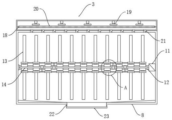
As shown in fig. 3 and 4, the stirring assembly 3 comprises a second motor 11, a transmission shaft 12, a plurality of groups of stirring rods 13, two groups of scraping plates 14, a plurality of groups of electric push rods 15, a plurality of groups of lantern rings 16, a connecting rod 17 and a heating part 18, wherein the second motor 11 is installed on the inner wall of the fermentation barrel 8, the transmission shaft 12 is installed at the output end of the second motor 11, a plurality of groups of stirring rods 13 are sleeved outside the transmission shaft 12, two groups of scraping plates 14 are installed on two sides of the transmission shaft 12, a plurality of groups of electric push rods 15 are installed in the transmission shaft 12, a plurality of groups of lantern rings 16 are sleeved outside the stirring rods 13, the connecting rod 17 is installed between the lantern rings 16, the heating part 18 is installed in the heating box 10, the heating part 18 comprises a plurality of groups of guide fans 19, a heating plate 20, a plurality of groups of one-way valves 21, a discharge port 22 and a sealing cover 23, a plurality of groups of guide fans 19 are installed in the heating box 10 through bolts, the heating plate 20 is clamped in the heating box 10, a plurality of groups of one-way valves 21 are embedded and arranged between the heating box 10 and the fermentation barrel 8, the discharge hole 22 is arranged at the bottom end of the fermentation barrel 8, the sealing cover 23 is sleeved and arranged outside the discharge hole 22, the transmission shaft 12 is rotationally connected with the inner wall of the fermentation barrel 8, the sealing cover 23 and the discharge hole 22 are rotationally combined through threads, the electric push rod 15 is connected with the connecting rod 17, the sealing cover 23 is unscrewed to put feed raw materials into the fermentation barrel 8, the sealing cover 23 and the discharge hole 22 are rotationally combined after the feeding is finished, the stirring rod 13 and the scraping plate 14 are driven to rotate by the motor 11, the feed raw materials can be stirred by the rotation of the stirring rod 13, the temperature in the fermentation barrel 8 can be increased by the guide fan 19 and the heating plate 20, the feed raw materials can be prevented from flowing into the heating box 10 by the one-way valve 21, the electric push rod 15 is used for driving the lantern ring 16 to move, so that residual feed on the surface of the stirring rod 13 can be scraped, and the scraper 14 can scrape residual feed raw materials on the inner wall of the fermentation barrel 8.
The utility model provides feed fermentation equipment for improving the utilization rate of raw materials, which has the following specific working principle:
when the fodder fermentation equipment is used, through being equipped with stirring subassembly 3, unscrew sealed lid 23 can put in the fermentation vat 8 with the fodder raw materials, it closes sealed lid 23 and discharge gate 22 soon after throwing the material, utilize No. two motor 11 to drive transmission shaft 12 rotation, transmission shaft 12's rotation drives puddler 13 and scraper blade 14 rotation, stirring of fodder raw materials can be to the rotation of puddler 13, utilize guide fan 19 and hot plate 20 to rise the temperature in the fermentation vat 8, utilize check valve 21 can prevent the fodder raw materials to flow to in the heating cabinet 10, do benefit to the fermentation to the fodder raw materials, after the fermentation is accomplished, utilize electric push rod 15 to drive connecting rod 17 to remove, the removal of connecting rod 17 drives the lantern ring 16 and removes, can scrape the fodder of puddler 13 surface residue, scraper blade 14 can scrape the fodder raw materials of fermentation vat 8 inner wall residue, avoid the waste of fodder raw materials, the utilization ratio of raw materials has been improved, through being equipped with rotating subassembly 2, when fermenting the fodder raw materials, utilize No. one motor 6 to drive transfer lever 7 to rotate, under the cooperation of auxiliary lever 9, transfer lever 7's rotation drives fermentation vat 8, do benefit to the full fermentation raw materials to the fodder in the fermentation vat 8.
Although embodiments of the present utility model have been shown and described, it will be understood by those skilled in the art that various changes, modifications, substitutions and alterations can be made therein without departing from the principles and spirit of the utility model, the scope of which is defined in the appended claims and their equivalents.
Claims (7)
1. The utility model provides a improve fodder fermentation equipment of raw materials utilization ratio, its characterized in that includes supporting baseplate (1), rotating assembly (2) and stirring subassembly (3), supporting baseplate (1) is made by metal material, multiunit shock pad is installed to supporting baseplate (1), rotating assembly (2) install at supporting baseplate (1) top, stirring subassembly (3) are installed on supporting baseplate (1) top and are located rotating assembly (2) one side.
2. The feed fermentation apparatus for improving utilization rate of raw materials according to claim 1, wherein: two groups of support plates (4) are mounted on the top end bolts of the support bottom plate (1), and the two groups of support plates (4) are symmetrically arranged.
3. The feed fermentation apparatus for improving utilization rate of raw materials according to claim 1, wherein: the rotary component (2) comprises a motor box (5), a motor (6), a transmission rod (7), a fermentation barrel (8), an auxiliary rod (9) and a heating box (10), wherein the motor box (5) is installed on one side of a supporting plate (4) through bolts, the motor (6) is installed in the motor box (5), the transmission rod (7) is installed at the output end of the motor (6), the fermentation barrel (8) is installed at one end of the transmission rod (7), the auxiliary rod (9) is installed on one side of the fermentation barrel (8), and the heating box (10) is installed at the top end of the fermentation barrel (8).
4. A feed fermentation apparatus for improving raw material utilization according to claim 3, wherein: the auxiliary rod (9) is rotatably connected with the supporting plate (4), and the fermentation barrel (8) is made of heat insulation materials.
5. The feed fermentation apparatus for improving utilization rate of raw materials according to claim 1, wherein: the stirring assembly (3) comprises a second motor (11), a transmission shaft (12), a plurality of groups of stirring rods (13), two groups of scraping plates (14), a plurality of groups of electric push rods (15), a plurality of groups of lantern rings (16), a connecting rod (17) and a heating part (18), wherein the second motor (11) is installed on the inner wall of the fermentation barrel (8), the transmission shaft (12) is installed at the output end of the second motor (11), a plurality of groups of stirring rods (13) are sleeved outside the transmission shaft (12), two groups of scraping plates (14) are installed on two sides of the transmission shaft (12), a plurality of groups of electric push rods (15) are installed in the transmission shaft (12), a plurality of groups of lantern rings (16) are sleeved outside the stirring rods (13), the connecting rod (17) is installed between the lantern rings (16), and the heating part (18) is installed in the heating box (10).
6. The feed fermentation apparatus for improving utilization rate of raw materials according to claim 5, wherein: the heating part (18) comprises a plurality of groups of guide fans (19), heating plates (20), a plurality of groups of one-way valves (21), a discharge port (22) and a sealing cover (23), wherein a plurality of groups of guide fans (19) are installed in the heating box (10) through bolts, the heating plates (20) are connected in a clamping mode and installed in the heating box (10), a plurality of groups of one-way valves (21) are embedded and installed between the heating box (10) and the fermentation barrel (8), the discharge port (22) is installed at the bottom end of the fermentation barrel (8), and the sealing cover (23) is sleeved and installed outside the discharge port (22).
7. The feed fermentation apparatus for improving utilization rate of raw materials according to claim 6, wherein: the transmission shaft (12) is rotationally connected with the inner wall of the fermentation barrel (8), the sealing cover (23) is screwed with the discharge hole (22) through threads, and the electric push rod (15) is connected with the connecting rod (17).
Priority Applications (1)
| Application Number | Priority Date | Filing Date | Title |
|---|---|---|---|
| CN202223471217.XU CN219010275U (en) | 2022-12-26 | 2022-12-26 | Fodder fermentation equipment capable of improving raw material utilization rate |
Applications Claiming Priority (1)
| Application Number | Priority Date | Filing Date | Title |
|---|---|---|---|
| CN202223471217.XU CN219010275U (en) | 2022-12-26 | 2022-12-26 | Fodder fermentation equipment capable of improving raw material utilization rate |
Publications (1)
| Publication Number | Publication Date |
|---|---|
| CN219010275U true CN219010275U (en) | 2023-05-12 |
Family
ID=86235466
Family Applications (1)
| Application Number | Title | Priority Date | Filing Date |
|---|---|---|---|
| CN202223471217.XU Active CN219010275U (en) | 2022-12-26 | 2022-12-26 | Fodder fermentation equipment capable of improving raw material utilization rate |
Country Status (1)
| Country | Link |
|---|---|
| CN (1) | CN219010275U (en) |
-
2022
- 2022-12-26 CN CN202223471217.XU patent/CN219010275U/en active Active
Similar Documents
| Publication | Publication Date | Title |
|---|---|---|
| CN110963827A (en) | Poultry and livestock leftover organic fertilizer fermentation machine containing biochar | |
| CN208279610U (en) | A kind of installation for fermenting convenient for feeding | |
| CN201309931Y (en) | Horizontal anaerobic reactor for producing methane based on solid fermentation of organic waste | |
| CN219010275U (en) | Fodder fermentation equipment capable of improving raw material utilization rate | |
| CN216808651U (en) | Fermenting installation is used in bio-fertilizer production | |
| CN214299794U (en) | High-efficient agitated vessel of digestion tank mud | |
| CN214022574U (en) | Intelligent control fermentation cylinder | |
| CN213446889U (en) | A equipment for fertilizer fermentation | |
| CN213202769U (en) | High-efficient fermenting installation of municipal administration mud | |
| CN115521835A (en) | White spirit fermentation device and processing method | |
| CN210278871U (en) | Heating and stirring device for chicken manure preparation | |
| CN212174948U (en) | Methane tank with good sealing performance | |
| CN211660724U (en) | High-efficient anaerobic fermentation treatment tank of kitchen garbage | |
| CN209685766U (en) | A kind of compound microorganism ferments device | |
| CN219194937U (en) | Biogas fermentation raw material stirring heat preservation device | |
| CN112111382A (en) | High-efficient marsh gas fermentation system | |
| CN219752195U (en) | Tank type fermentation device for livestock and poultry manure | |
| CN2856052Y (en) | Complete equipment for marsh gas from excrement | |
| CN214937389U (en) | Stirring device for strain culture raw materials | |
| CN215799472U (en) | Processing fermenting installation for pig feed | |
| CN213436140U (en) | Food fermentation equipment | |
| CN219670453U (en) | Saccharification pot is used in beer production processing | |
| CN220265600U (en) | Pollution-free solanaceous fruit organic fertilizer processing device | |
| CN220166169U (en) | Chinese honeylocust fermentation tank | |
| CN220265672U (en) | Fermentation tank for bio-pharmaceuticals |
Legal Events
| Date | Code | Title | Description |
|---|---|---|---|
| GR01 | Patent grant | ||
| GR01 | Patent grant |