A equipment for fertilizer fermentation
Technical Field
The utility model relates to a fertilizer fermentation technical field specifically is an equipment for fertilizer fermentation.
Background
In traditional fertilizer fermentation technique, especially when the organic fertilizer to raising animal excrement and urine class is handled, all directly pile together this type of organic fertilizer and ferment usually, such fermentation mode not only fermentation inefficiency, the fermentation is not abundant, can produce marsh gas moreover, causes to be full of the stink in the air, influences the air quality, and the fermentation storehouse does not have the stirring, turns over a device, and the material is easy to be compacted.
SUMMERY OF THE UTILITY MODEL
Not enough to prior art, the utility model provides an equipment for fertilizer fermentation has solved the fermentation inefficiency, and the fermentation is insufficient, produces being full of the stink in the cause air of marsh gas, the easy compaction problem of material.
In order to achieve the above purpose, the utility model discloses a following technical scheme realizes: an apparatus for fermenting organic fertilizer comprises a fermentation barrel body, wherein fixed supporting legs are installed at four corners of the bottom of the fermentation barrel body, a feeding funnel is installed at one side of the top of the fermentation barrel body, a fixed rotating shaft is installed on the feeding funnel, a movable cover plate is sleeved on the fixed rotating shaft and is rotatably connected with the fixed rotating shaft, the movable cover plate is movably connected with the feeding funnel, a discharging port is formed in the center of the bottom of the fermentation barrel body, a discharging valve is arranged on the discharging port, and a stirring fermentation mechanism is arranged on the fermentation barrel body;
stirring fermentation mechanism, it includes: the device comprises two groups of opposite rotating connecting pieces, one group of opposite rotating shafts, a stirring connecting rod, crushing screw threads, a driven gear, a driving motor, a driving gear, a heater and a heating wire;
the fermentation vat body is installed inside to two sets of relative rotation connecting pieces, a set of relative axis of rotation suit is on two sets of relative rotation connecting pieces, the fermentation vat body is stretched out to a set of relative axis of rotation, the stirring connecting rod is installed in the axis of rotation, broken thread is installed in the axis of rotation, driven gear installs the top at the axis of rotation, driving motor installs at fermentation vat body top, driving motor's rotation end is upwards, the driving gear is installed on driving motor's rotation end, driving gear and driven gear interlock, the heater is installed in fermentation vat body one side, the heater strip is established at the fermentation vat body on the surface.
Preferably, an air pump is arranged on one side of the fermentation barrel body, an exhaust tube is arranged between the air pump and the fermentation barrel body, an air storage tank is arranged on one side of the air pump, a connecting pipe is arranged between the air storage tank and the air pump, and an air valve is installed on the air storage tank.
Preferably, the movable cover plate is provided with a fixed handle, and the bottom of the movable cover plate is provided with a rubber sealing gasket.
Preferably, the agitator connecting rods on the set of opposed rotatable shafts are offset from one another.
Preferably, the heating wire and the heater are electrically connected.
Preferably, the connecting pipe is connected with the gas storage tank through a flange.
Advantageous effects
The utility model provides an equipment for fertilizer fermentation possesses following beneficial effect, and this device can stir and breakage the fertilizer, stirs efficiently, and the fermentation is even abundant, prevents the material compaction, can heat the fermenter body, improves fermentation efficiency, can collect marsh gas, utilizes marsh gas, prevents to influence the air quality.
Drawings
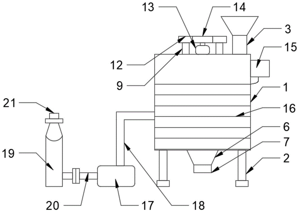
Fig. 1 is a schematic diagram of the device for fermenting organic fertilizer.
Fig. 2 is a schematic diagram of the stirring fermentation mechanism of the present invention.
Fig. 3 is a partial enlarged view of the device for fermenting organic fertilizer.
In the figure: 1. a fermenter body; 2. a fixed support leg; 3. a feed hopper; 4. fixing the rotating shaft; 5. a removable cover plate; 6. a discharge port; 7. a discharge valve; 8. rotating the connecting piece; 9. A rotating shaft; 10. a stirring connecting rod; 11. crushing screw teeth; 12. a driven gear; 13. a drive motor; 14. a driving gear; 15. a heater; 16. heating wires; 17. an air pump; 18. An air exhaust pipe; 19. a gas storage tank; 20. a connecting pipe; 21. an air valve; 22. fixing a handle; 23. A rubber gasket; 24. and (4) a flange.
Detailed Description
The technical solutions in the embodiments of the present invention will be described clearly and completely with reference to the accompanying drawings in the embodiments of the present invention, and it is obvious that the described embodiments are only some embodiments of the present invention, not all embodiments. Based on the embodiments in the present invention, all other embodiments obtained by a person skilled in the art without creative work belong to the protection scope of the present invention.
Referring to fig. 1-3, the present invention provides a technical solution: an apparatus for fermenting organic fertilizer comprises a fermentation barrel body 1, wherein fixed support legs 2 are arranged at four corners of the bottom of the fermentation barrel body 1, a feeding funnel 3 is arranged on one side of the top of the fermentation barrel body 1, a fixed rotating shaft 4 is arranged on the feeding funnel 3, a movable cover plate 5 is sleeved on the fixed rotating shaft 4, the movable cover plate 5 is rotatably connected with the fixed rotating shaft 4, the movable cover plate 5 is movably connected with the feeding funnel 3, a discharging port 6 is arranged at the center of the bottom of the fermentation barrel body 1, a discharging valve 7 is arranged on the discharging port 6, and a stirring fermentation mechanism is arranged on the fermentation barrel body 1; stirring fermentation mechanism, it includes: two groups of opposite rotating connecting pieces 8, one group of opposite rotating shafts 9, a stirring connecting rod 10, crushing threads 11, driven gears 12, a driving motor 13, a driving gear 14, a heater 15 and a heating wire 16; the fermentation vat comprises a fermentation vat body 1, two groups of opposite rotating connecting pieces 8, a group of opposite rotating shafts 9, a stirring connecting rod 10, a crushing screw thread 11, a driven gear 12, a driving motor 13, a heating wire 16 and a heating wire, wherein the two groups of opposite rotating connecting pieces 8 are arranged inside the fermentation vat body 1, the two groups of opposite rotating shafts 9 are sleeved on the two groups of opposite rotating connecting pieces 8, the one group of opposite rotating shafts 9 extend out of the fermentation vat body 1, the stirring connecting rod 10 is arranged on the rotating shafts 9, the crushing screw thread 11 is arranged on the rotating shafts 9, the driven gear 12 is arranged at the top of the rotating shafts 9, the driving motor 13 is arranged at the top of the fermentation vat body 1, the rotating end of the driving motor 13 is upward, the; an air pump 17 is arranged on one side of the fermentation barrel body 1, an air exhaust pipe 18 is arranged between the air pump 17 and the fermentation barrel body 1, an air storage tank 19 is arranged on one side of the air pump 17, a connecting pipe 20 is arranged between the air storage tank 19 and the air pump 17, and an air valve 21 is arranged on the air storage tank 19; a fixed handle 22 is arranged on the movable cover plate 5, and a rubber sealing gasket 23 is arranged at the bottom of the movable cover plate 5; the stirring connecting rods 10 on the group of opposite rotating shafts 9 are staggered with each other; the heating wire 16 is electrically connected with the heater 15; the connection pipe 20 is connected to the gas tank 19 via a flange 24.
All the electrical components in the present application are connected with the power supply adapted to the electrical components through the wires, and an appropriate controller should be selected according to actual conditions to meet the control requirements, and specific connection and control sequences should be obtained.
Example (b): when the fermentation tank is used, a user rotates the movable cover plate 5 through the fixed handle 22, the movable cover plate 5 rotates on the feeding funnel 3 through the fixed rotating shaft 4, the feeding funnel 3 is opened, the user pours organic fertilizer into the feeding funnel 3, the organic fertilizer in the feeding funnel 3 flows into the fermentation tank body 1, the user rotates the movable cover plate 5 back to the original position, the feeding funnel 3 is sealed through the rubber sealing gasket 23 below the movable cover plate 5, the driving motor 13 is started, the rotating end of the driving motor 13 drives the driving gear 14 to rotate, the driving gear 14 is meshed with the driven gear 12 to drive the driven gear 12 to rotate, the driven gear 12 drives the rotating shaft 9 to rotate on the rotating connecting piece 8, the rotating shaft 9 drives the stirring connecting rod 10 to rotate to stir the organic fertilizer, the crushing screw 11 is driven by the stirring connecting rod 10 to rotate to crush the organic fertilizer, can stir and the breakage to the fertilizer, it is efficient to stir, the fermentation is even abundant, prevent the material compaction, start heater 15 simultaneously, heater 15 heats fermenter body 1 through heater strip 16, the heat is led into in the fermenter body 1, improve fermentation efficiency through the heating, when 1 inside marsh gas that produces of fermenter body, start air pump 17, air pump 17 takes out the marsh gas in fermenter body 1 through exhaust tube 18, collect the storage in carrying marsh gas storage tank 19 through connecting pipe 20, can dismantle the change to gas storage tank 19 through flange 24, utilize marsh gas, prevent to influence air quality, after the fertilizer fermentation is accomplished, open discharge gate 6 through discharge valve 7, the fertilizer in the fermenter body 1 flows through discharge gate 6, and is simple in operation and convenient to use.
It is noted that, herein, relational terms such as first and second, and the like may be used solely to distinguish one entity or action from another entity or action without necessarily requiring or implying any actual such relationship or order between such entities or actions. Also, the terms "comprises," "comprising," or any other variation thereof, are intended to cover a non-exclusive inclusion, such that a process, method, article, or apparatus that comprises a list of elements does not include only those elements but may include other elements not expressly listed or inherent to such process, method, article, or apparatus. Without further limitation. The use of the phrase "comprising one of the elements does not exclude the presence of other like elements in the process, method, article, or apparatus that comprises the element.
Although embodiments of the present invention have been shown and described, it will be appreciated by those skilled in the art that changes, modifications, substitutions and alterations can be made in these embodiments without departing from the principles and spirit of the invention, the scope of which is defined in the appended claims and their equivalents.