CN218874845U - Novel burring equipment - Google Patents
Novel burring equipment Download PDFInfo
- Publication number
- CN218874845U CN218874845U CN202223254173.5U CN202223254173U CN218874845U CN 218874845 U CN218874845 U CN 218874845U CN 202223254173 U CN202223254173 U CN 202223254173U CN 218874845 U CN218874845 U CN 218874845U
- Authority
- CN
- China
- Prior art keywords
- wall
- plate
- fixed
- movable
- motor
- Prior art date
- Legal status (The legal status is an assumption and is not a legal conclusion. Google has not performed a legal analysis and makes no representation as to the accuracy of the status listed.)
- Active
Links
Images


Classifications
-
- Y—GENERAL TAGGING OF NEW TECHNOLOGICAL DEVELOPMENTS; GENERAL TAGGING OF CROSS-SECTIONAL TECHNOLOGIES SPANNING OVER SEVERAL SECTIONS OF THE IPC; TECHNICAL SUBJECTS COVERED BY FORMER USPC CROSS-REFERENCE ART COLLECTIONS [XRACs] AND DIGESTS
- Y02—TECHNOLOGIES OR APPLICATIONS FOR MITIGATION OR ADAPTATION AGAINST CLIMATE CHANGE
- Y02P—CLIMATE CHANGE MITIGATION TECHNOLOGIES IN THE PRODUCTION OR PROCESSING OF GOODS
- Y02P70/00—Climate change mitigation technologies in the production process for final industrial or consumer products
- Y02P70/10—Greenhouse gas [GHG] capture, material saving, heat recovery or other energy efficient measures, e.g. motor control, characterised by manufacturing processes, e.g. for rolling metal or metal working
Abstract
The utility model discloses a novel burring equipment, the on-line screen storage device comprises a supporting pedestal and is characterized by further comprising, support the base top and install operation platform, the fixed plate is installed to operation platform top one end, accommodate the lead screw is installed to operation platform intermediate position inner wall, the accommodate the lead screw one end outside is equipped with the fly leaf, the joint dish is all installed to one side inner wall that fixed plate and fly leaf are relative, the sliding seat is installed to operation platform one side inner wall, the mounting panel is installed at the sliding seat top, mounting panel one side is equipped with the board of polishing. The utility model discloses a distance between fly leaf and the fixed plate can be adjusted in accommodate the lead screw's rotation for two joint discs can carry out the centre gripping to the machined part of different length, and second motor work makes the joint disc can drive machined part and rotates, and two pneumatic cylinder work make the board of polishing can carry out burring work to the different positions of machined part, can improve machined part's machining efficiency.
Description
Technical Field
The utility model relates to a machine parts processing equipment technical field, concretely relates to novel burring equipment.
Background
Deburring refers to the removal of extremely coarse metal particles from the surface of a part. The deburring method has the advantages of remarkable processing advantages of difficult-to-process materials, complex shapes or thin-wall parts, high productivity and good surface quality. Grinding such as deburring, polishing, cleaning, chamfering and surface hardness improvement is simultaneously completed, and accurate small-shaped parts, irregular parts and the like are used for deburring.
The prior art has the following defects: 1. when the existing deburring equipment is used for deburring a machined part, due to the fact that the machined part is different in shape and size, the equipment cannot conveniently clamp and fix the machined part when used for deburring the machined part, the machined part is deviated during deburring, and the machined part is easily damaged;
2. when the existing deburring equipment is used for deburring machined parts, the positions of the grinding mechanisms cannot be conveniently and fast adjusted, so that the grinding mechanisms cannot be used for grinding different positions of the machined parts, the equipment cannot rapidly complete deburring work on the machined parts, and the machining efficiency of the machined parts can be influenced.
The above information disclosed in this background section is only for enhancement of understanding of the background of the disclosure and therefore it may contain information that does not constitute prior art that is already known to a person of ordinary skill in the art.
Disclosure of Invention
The utility model aims at providing a novel burring equipment, can adjust the distance between fly leaf and the fixed plate through accommodate the lead screw's rotation, make two joint dishes can carry out the centre gripping and fix to the machined part of different length, second pneumatic cylinder work can drive the board of polishing and extend or contract, second motor work makes the joint dish can drive the machined part of machine and rotates, the horizontal position of the board of polishing can be adjusted in first pneumatic cylinder work simultaneously, make the board of polishing can polish burring work to the different positions of the different size machined part of different shapes, make that the device can be convenient carry out burring work to the machined part, can improve machined part's machining efficiency, with the above-mentioned weak point in the solution technology.
In order to achieve the above object, the present invention provides the following technical solutions: the utility model provides a novel deburring equipment, includes and supports the base, the top fixed mounting who supports the base has operation platform, operation platform's top one end fixed mounting has the fixed plate, operation platform's intermediate position has seted up the activity groove, the inner wall in activity groove rotates and installs accommodate the lead screw, accommodate the lead screw's one end is provided with first motor, the one end outside that the fixed plate was kept away from to accommodate the lead screw is provided with the fly leaf, the mounting groove has all been seted up to one side that fixed plate and fly leaf are relative, two the inner wall in mounting groove all rotates installs the joint dish, two the equal fixed mounting of the one end that the joint dish carried on the back mutually has the axis of rotation, one of them one end that the joint dish was kept away from in the axis of rotation is provided with the second motor, limited groove is seted up to one side of operation platform, the inner wall movable mounting in limited groove has the sliding seat, the one end of sliding seat is provided with first pneumatic cylinder, the top fixed mounting panel of sliding seat, one side of mounting panel is provided with the second pneumatic cylinder, the output of second pneumatic cylinder is provided with the board of polishing.
Preferably, three fixed slots are formed in one end, far away from the inner wall of the mounting groove, of the clamping disc, and the three fixed slots are arranged in an equidistant annular mode.
Preferably, the inner wall of the fixing groove is fixedly provided with an electric push rod, and the electric push rod is fixedly provided with a clamping plate at one end far away from the inner wall of the fixing groove.
Preferably, the bottom of the movable plate is fixedly provided with a sliding block, the inner wall of the sliding block is in threaded connection with the outer side of the adjusting screw rod, and the outer side of the sliding block is movably connected with the inner wall of the movable groove.
Preferably, one end of the fixed plate, which is far away from the movable plate, is fixedly connected with a second motor, and the second motor is in transmission connection with one of the rotating shafts through an output shaft.
Preferably, the outer wall of one end of the operating platform is fixedly connected with a first motor, and the first motor is in transmission connection with the adjusting screw rod through an output shaft.
Preferably, the outer wall of one end of the operating platform is fixedly connected with a first hydraulic cylinder, and the first hydraulic cylinder is in transmission connection with the movable base through an output shaft.
Preferably, one side and the second pneumatic cylinder fixed connection of mounting panel, the output fixed mounting of second pneumatic cylinder has the connecting plate, one side and the board fixed connection of polishing of mounting panel are kept away from to the connecting plate.
In the technical scheme, the utility model provides a technological effect and advantage:
1. the movable plate can be driven to move by rotation of the adjusting screw rod, so that the distance between the movable plate and the fixed plate can be adjusted, the two clamping discs can clamp and fix mechanical workpieces with different lengths, the second hydraulic cylinder can drive the polishing plate to extend or contract, the second motor can drive one of the rotating shafts to rotate, so that the clamping discs can drive the mechanical workpieces to rotate, meanwhile, the first hydraulic cylinder can adjust the horizontal positions of the polishing plate, so that the polishing plate can polish and deburr different positions of the mechanical workpieces with different shapes and sizes, the device can conveniently deburr the mechanical workpieces, and the machining efficiency of the mechanical workpieces can be improved;
2. can inject the removal of slider through the activity groove, and then can inject the removal of fly leaf, make the fly leaf at the removal in-process remain stable, and then make two joint discs can be stable carry out centre gripping and fixed to machined part, the activity groove sets up to the structure of through-hole simultaneously, make the piece that the in-process of polishing produced can be through the whereabouts of activity groove, can avoid the piece to pile up in the activity inslot portion and cause the influence to the rotation of adjusting screw, and then can reduce the wearing and tearing between adjusting screw and the slider.
Drawings
In order to more clearly illustrate the embodiments of the present application or the technical solutions in the prior art, the drawings needed to be used in the embodiments will be briefly described below, and it is obvious that the drawings in the following description are only some embodiments described in the present invention, and other drawings can be obtained by those skilled in the art according to these drawings.
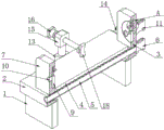
Fig. 1 is a front perspective structure view of the present invention.
Fig. 2 is a rear perspective view of the present invention.
Fig. 3 is a front perspective sectional view of the present invention.
Fig. 4 is an enlarged view of a portion a of fig. 3 according to the present invention.
Fig. 5 is an exploded perspective view of the present invention.
Description of reference numerals:
1. a support base; 2. an operating platform; 3. a fixing plate; 4. a movable groove; 5. adjusting the screw rod; 6. a first motor; 7. a movable plate; 8. mounting grooves; 9. a clamping disc; 10. a rotating shaft; 11. a second motor; 12. defining a slot; 13. a movable seat; 14. a first hydraulic cylinder; 15. mounting a plate; 16. a second hydraulic cylinder; 17. a connecting plate; 18. grinding the plate; 19. fixing grooves; 20. an electric push rod; 21. a clamping plate; 22. a slide block.
Detailed Description
The utility model provides a as shown in fig. 1-5 novel burring equipment, including supporting base 1, the top fixed mounting who supports base 1 has operation platform 2, operation platform 2's top one end fixed mounting has fixed plate 3, movable groove 4 has been seted up to operation platform 2's intermediate position, movable groove 4's inner wall rotates installs accommodate the lead screw 5, accommodate the lead screw 5's one end is provided with first motor 6, accommodate the lead screw 5 and keep away from the one end outside of fixed plate 3 and be provided with fly leaf 7, mounting groove 8, two has all been seted up to fixed plate 3 and fly leaf 7 one side relative mounting groove 8's inner wall all rotates and installs joint dish 9, two joint dish 9 looks back to each other's the equal fixed mounting of one end has axis of rotation 10, one of them axis of rotation 10 is kept away from joint dish 9's one end and is provided with second motor 11, one side of operation platform 2 is seted up limited groove 12, the inner wall movable mounting of limited groove 12 has movable seat 13, the one end of movable seat 13 is provided with first pneumatic cylinder 14, the top fixed mounting panel 15 of movable seat 13 has mounting panel, one side of mounting panel 15 is provided with second pneumatic cylinder 16, the adjustable clamp dish 18 can grind the distance through the fixed distance that the fixed plate that the adjustable lead screw is adjusted to the fixed plate 3 and the adjustable lead screw makes the fixed plate 7 that the fixed that the work is carried out the deburring is carried out on the fixed distance to the fixed plate, and the fixed plate 18.
Further, in the above technical scheme, three fixed grooves 19, three are seted up to the one end that chucking plate 9 kept away from the inner wall of mounting groove 8 fixed slot 19 is equidistant annular array, and fixed groove 19 can be injectd the removal of grip block 21 for grip block 21 remains stable in the accommodation process, and is three the equal fixed mounting of inner wall of fixed groove 19 has electric putter 20, and is three the equal fixed mounting of one end that electric putter 20 kept away from the inner wall of fixed groove 19 has grip block 21, and fixed groove 19 can be installed and fixed electric putter 20, and the distance between three grip block 21 can be adjusted in electric putter 20 work for three grip block 21 can carry out the centre gripping and fix the machined part of equidimension not.
Further, in the above technical solution, a sliding block 22 is fixedly installed at the bottom of the movable plate 7, an inner wall of the sliding block 22 is in threaded connection with an outer side of the adjusting screw rod 5, an outer side of the sliding block 22 is movably connected with an inner wall of the movable groove 4, and the rotation of the adjusting screw rod 5 enables the sliding block 22 to move along the inner wall of the movable groove 4 at the outer side thereof, so as to drive the movable plate 7 to move, and further adjust the distance between the movable plate 7 and the fixed plate 3.
Further, in the above technical scheme, one end of the fixed plate 3, which is far away from the movable plate 7, is fixedly connected with the second motor 11, the second motor 11 is in transmission connection with one of the rotating shafts 10 through an output shaft, the fixed plate 3 can mount and fix the second motor 11, the second motor 11 works to enable one of the rotating shafts 10 to rotate, and then one of the chuck plates 9 rotates, so that the workpiece also rotates therewith, and further the polishing plate 18 can perform polishing operations on different positions of the workpiece.
Further, in the above technical scheme, the outer wall of one end of the operating platform 2 is fixedly connected with the first motor 6, the first motor 6 is in transmission connection with the adjusting screw rod 5 through an output shaft, the operating platform 2 can mount and fix the first motor 6, and the first motor 6 works to enable the adjusting screw rod 5 to rotate so as to provide power for position adjustment of the movable plate 7.
Further, in the above technical scheme, the outer wall of one end of the operating platform 2 is fixedly connected with the first hydraulic cylinder 14, the first hydraulic cylinder 14 is in transmission connection with the movable seat 13 through an output shaft, the operating platform 2 can install and fix the first hydraulic cylinder 14, the first hydraulic cylinder 14 can drive the movable seat 13 to move along the inner wall of the limiting groove 12 when working, and then the position of the polishing plate 18 can be adjusted, so that the polishing plate 18 can perform deburring operation on different positions of a workpiece, one side of the mounting plate 15 is fixedly connected with the second hydraulic cylinder 16, the output end of the second hydraulic cylinder 16 is fixedly provided with the connecting plate 17, one side of the connecting plate 17, which is far away from the mounting plate 15, is fixedly connected with the polishing plate 18, the mounting plate 15 can install and fix the second hydraulic cylinder 16, the connecting plate 17 can install and fix the polishing plate 18, so that a worker can conveniently replace the polishing plate 18, and the second hydraulic cylinder 16 can drive the polishing plate 18 to extend or retract, so that workpieces of different sizes can be deburred by the polishing plate 18.
The implementation mode is specifically as follows: when the deburring operation is performed on the machined part, one end of the machined part is contacted with the clamping disc 9 at one end of the fixed plate 3, so that the distance between the three clamping plates 21 can be adjusted through the three electric push rods 20, the three clamping plates 21 can clamp and fix one end of the machined part, the adjusting screw 5 is rotated through the operation of the first motor 6, the slider 22 can move along the inner wall of the movable groove 4 at the outer side of the slider, so that the distance between the movable plate 7 and the fixed plate 3 can be adjusted, the clamping disc 9 at one end of the movable plate 7 can clamp and fix the other end of the machined part, meanwhile, the second hydraulic cylinder 16 can work to enable the polishing plate 18 to extend towards the machined part, so that the polishing plate 18 can polish the machined part, meanwhile, the second motor 11 works to enable one rotating shaft 10 to rotate, so that one clamping disc 9 rotates, so that the polishing plate 18 can drive the machining plate 18 to rotate towards the other clamping disc 9, so that the polishing plate 18 can polish different positions of the machined part, and further, the deburring can be conveniently performed by the movable polishing plate polishing device for deburring the machined parts, so that the deburring can be performed by the movable polishing plate 18 along the polishing positions and the movable polishing seat for deburring of the fixed polishing plate, and the adjustable working positions, so that the adjustable deburring can be conveniently performed by the movable plate for the adjustable working positions of the movable polishing plate 18, and then can improve machined part's burring efficiency, this embodiment has specifically solved among the prior art device can't be convenient not the different positions to the machined part of different shapes unidimensional and has polished the burring work, problem that machining efficiency is low.
While certain exemplary embodiments of the present invention have been described above by way of illustration only, it will be apparent to those of ordinary skill in the art that the described embodiments may be modified in various different ways without departing from the spirit and scope of the present invention. Accordingly, the drawings and description are to be regarded as illustrative in nature and not as restrictive on the scope of the appended claims.
Claims (8)
1. The utility model provides a novel burring equipment, includes support base (1), its characterized in that: an operation platform (2) is fixedly installed at the top of the supporting base (1), a fixed plate (3) is fixedly installed at one end of the top of the operation platform (2), a movable groove (4) is formed in the middle of the operation platform (2), an adjusting screw rod (5) is installed on the inner wall of the movable groove (4) in a rotating mode, a first motor (6) is arranged at one end of the adjusting screw rod (5), a movable plate (7) is arranged on the outer side of the end, far away from the fixed plate (3), of the adjusting screw rod (5), mounting grooves (8) are formed in one side, opposite to the fixed plate (7), of the fixed plate (3) and the movable plate (7), clamping plates (9) are installed on the inner walls of the two mounting grooves (8) in a rotating mode, a rotating shaft (10) is fixedly installed at the end, far away from the clamping plates (9), of one rotating shaft (10) is provided with a second motor (11), a limiting groove (12) is formed in one side of the operation platform (2), a movable seat (13) is movably installed on the inner wall of the limiting groove (12), a movable seat (13) is provided with a first hydraulic cylinder (14), a mounting plate (15) is arranged at one side of the movable seat (15), and a grinding plate (18) is arranged at the output end of the second hydraulic cylinder (16).
2. The novel deburring apparatus of claim 1, wherein: three fixed slots (19) have been seted up to the one end that mounting groove (8) inner wall was kept away from in joint dish (9), and is three fixed slot (19) are equidistant annular arrangement.
3. The novel deburring apparatus of claim 2, wherein: the inner wall of the three fixing grooves (19) is fixedly provided with an electric push rod (20), and the end, far away from the inner wall of the fixing groove (19), of the electric push rod (20) is fixedly provided with a clamping plate (21).
4. The novel deburring apparatus of claim 1, wherein: the bottom fixed mounting of fly leaf (7) has slider (22), the outside threaded connection of the inner wall and accommodate the lead screw (5) of slider (22), the outside and the activity groove (4) inner wall swing joint of slider (22).
5. The novel deburring apparatus of claim 1, wherein: one end, far away from the movable plate (7), of the fixed plate (3) is fixedly connected with a second motor (11), and the second motor (11) is in transmission connection with one of the rotating shafts (10) through an output shaft.
6. The novel deburring apparatus of claim 1, wherein: the outer wall of one end of the operating platform (2) is fixedly connected with a first motor (6), and the first motor (6) is in transmission connection with the adjusting screw rod (5) through an output shaft.
7. The novel deburring apparatus of claim 1, wherein: the outer wall of one end of the operating platform (2) is fixedly connected with a first hydraulic cylinder (14), and the first hydraulic cylinder (14) is in transmission connection with the movable base (13) through an output shaft.
8. The novel deburring apparatus of claim 1, wherein: one side and second pneumatic cylinder (16) fixed connection of mounting panel (15), the output fixed mounting of second pneumatic cylinder (16) has connecting plate (17), one side and the board (18) fixed connection of polishing of mounting panel (15) are kept away from in connecting plate (17).
Priority Applications (1)
| Application Number | Priority Date | Filing Date | Title |
|---|---|---|---|
| CN202223254173.5U CN218874845U (en) | 2022-12-06 | 2022-12-06 | Novel burring equipment |
Applications Claiming Priority (1)
| Application Number | Priority Date | Filing Date | Title |
|---|---|---|---|
| CN202223254173.5U CN218874845U (en) | 2022-12-06 | 2022-12-06 | Novel burring equipment |
Publications (1)
| Publication Number | Publication Date |
|---|---|
| CN218874845U true CN218874845U (en) | 2023-04-18 |
Family
ID=85978525
Family Applications (1)
| Application Number | Title | Priority Date | Filing Date |
|---|---|---|---|
| CN202223254173.5U Active CN218874845U (en) | 2022-12-06 | 2022-12-06 | Novel burring equipment |
Country Status (1)
| Country | Link |
|---|---|
| CN (1) | CN218874845U (en) |
-
2022
- 2022-12-06 CN CN202223254173.5U patent/CN218874845U/en active Active
Similar Documents
| Publication | Publication Date | Title |
|---|---|---|
| CN211638971U (en) | Turning and polishing integrated machine for machining | |
| CN111618670A (en) | Adjustable twist drill grinding device | |
| CN210677738U (en) | Lathe for polishing and cutting special-shaped workpiece | |
| CN211841257U (en) | Center hole grinding machine for precision grinding | |
| CN218874845U (en) | Novel burring equipment | |
| CN211465972U (en) | Polisher positioner of usefulness is polished at furniture edges and corners | |
| JPS5845850A (en) | Method and machine for subjecting eccentric shaft cross area to circular processing | |
| CN218837344U (en) | Numerical control grinding machine capable of realizing curved surface grinding | |
| CN107717642A (en) | A kind of blade grinding machine and control method with double end feeding | |
| JP2011224668A (en) | Lens grinding method equipped with grinding wheel automatic exchanging device, and lens grinding device thereof | |
| CN216681460U (en) | Automatic plate part grinding machine | |
| CN210757183U (en) | Angle-adjustable grinding wheel dresser and grinding machine with same | |
| CN212946865U (en) | Adjustable twist drill grinding device | |
| CN210757010U (en) | Numerical control grinding machine | |
| CN211490954U (en) | Grinding machine with stable clamping function | |
| CN211728700U (en) | Multifunctional grinding machine | |
| CN110842714A (en) | Multifunctional grinding machine | |
| CN218575724U (en) | Computer face frame equipment of polishing | |
| CN219562565U (en) | High-precision five-axis grinding machine | |
| CN110549198A (en) | Internal spherical surface grinding machine | |
| CN218746674U (en) | Polisher that can be used to medical accessory manufacturing usefulness | |
| CN219358914U (en) | High-precision grinding machine mechanism for spindle | |
| CN219403616U (en) | Machining equipment of polishing | |
| CN110549217B (en) | Numerical control grinding machine | |
| CN215847482U (en) | Hardware high-precision polishing and grinding device |
Legal Events
| Date | Code | Title | Description |
|---|---|---|---|
| GR01 | Patent grant | ||
| GR01 | Patent grant |