CN218839092U - Automobile suspension plate support structure - Google Patents
Automobile suspension plate support structure Download PDFInfo
- Publication number
- CN218839092U CN218839092U CN202223083892.5U CN202223083892U CN218839092U CN 218839092 U CN218839092 U CN 218839092U CN 202223083892 U CN202223083892 U CN 202223083892U CN 218839092 U CN218839092 U CN 218839092U
- Authority
- CN
- China
- Prior art keywords
- seat
- spring
- movable
- movably connected
- plate
- Prior art date
- Legal status (The legal status is an assumption and is not a legal conclusion. Google has not performed a legal analysis and makes no representation as to the accuracy of the status listed.)
- Active
Links
Images


Classifications
-
- Y—GENERAL TAGGING OF NEW TECHNOLOGICAL DEVELOPMENTS; GENERAL TAGGING OF CROSS-SECTIONAL TECHNOLOGIES SPANNING OVER SEVERAL SECTIONS OF THE IPC; TECHNICAL SUBJECTS COVERED BY FORMER USPC CROSS-REFERENCE ART COLLECTIONS [XRACs] AND DIGESTS
- Y02—TECHNOLOGIES OR APPLICATIONS FOR MITIGATION OR ADAPTATION AGAINST CLIMATE CHANGE
- Y02T—CLIMATE CHANGE MITIGATION TECHNOLOGIES RELATED TO TRANSPORTATION
- Y02T10/00—Road transport of goods or passengers
- Y02T10/10—Internal combustion engine [ICE] based vehicles
- Y02T10/40—Engine management systems
Abstract
The utility model discloses an automobile suspension plate support structure, which comprises a support plate seat, a reinforcing rib, a joint seat and a buffer seat; the suspension plate support is characterized in that the support plate seat is fixedly connected with the reinforcing ribs, the reinforcing ribs and the connector seat, a buffer seat is arranged on one side of the support plate seat and comprises a fixed seat, a movable seat, a connecting seat and a spring, the fixed seat is movably connected with the support plate seat, the fixed seat is movably connected with the movable seat, the connecting seat is fixedly connected with the movable seat, and the spring is movably connected with the movable seat, and relates to the field of suspension plate supports. The utility model discloses a go out the screw rod from two spiro unions in screw back, wear out the fixing base with the screw rod and then go out from a screw spiral shell, take the cushion socket out from the layer board seat through the gyro wheel after that, can change the inside spring of cushion socket to the sustainable roll of in-process gyro wheel that the cushion socket was taken out makes the cushion socket take out smoothly, avoids the cushion socket to be blocked and dies, makes the spring change smoothly and convenient.
Description
Technical Field
The utility model relates to a suspension board holds in the palm the field, specifically is an automobile suspension board holds in palm structure.
Background
The suspension is a general term for all force-transmitting connecting devices between a frame (or a load-bearing vehicle body) and an axle (or a wheel) of an automobile, and has the functions of transmitting force and torque acting between the wheel and the frame, buffering impact force transmitted to the frame or the vehicle body from an uneven road surface, and reducing vibration caused by the impact force so as to ensure that the automobile can run smoothly.
Because the board holds in the palm needs to fix the suspension during suspension work, the board holds in the palm can touch ground and lead to the board to hold in the palm the damage when the vehicle jolts, consequently, there is the structure that sets up the board support into buffering shock attenuation, when the vehicle jolts and leads to the board support striking, the inside buffering shock-absorbing structure of board support can effectually cushion the shock attenuation to the board support, but its inside buffering shock-absorbing structure adopts the spring to realize usually, it is well known that, although the spring can cushion the shock attenuation but the spring can damage after absorbing the energy, just as publication No. CN201811221745.5, a board support for automotive suspension discloses, the spring can damage after absorbing the energy, but this patent does not disclose how to maintain, change the spring that damages to still mostly can not replace to this patent, and prior art also mostly is the design that can not replace the spring, lead to the use of board support, maintenance and change cost is higher.
SUMMERY OF THE UTILITY MODEL
An object of the utility model is to provide an automobile suspension board holds in palm structure to solve the problem that proposes among the above-mentioned background art.
In order to achieve the above object, the utility model provides a following technical scheme: a kind of automotive suspension board holds in the palm the structure, including holding in the palm the board seat, stiffening rib, joint seat and cushion; the supporting plate seat is fixedly connected with the reinforcing ribs and the joint seat, one side of the supporting plate seat is provided with a buffer seat, the buffer seat comprises a fixed seat, a movable seat, a connecting seat and a spring, the fixed seat is movably connected with the supporting plate seat, the fixed seat is movably connected with the movable seat, the connecting seat is fixedly connected with the movable seat, and the spring is movably connected with the movable seat.
As a further aspect of the present invention: the inside of fixing base is provided with the gyro wheel, the spout has been seted up to the inside of layer board seat, the fixing base is pegged graft with the spout, fixing base and gyro wheel roll connection, gyro wheel and spout sliding connection.
As the utility model discloses further scheme again: one side of the fixed seat, which is far away from the supporting plate seat, is fixedly connected with a first clamping rail, one side of the movable seat, which is far away from the connecting seat, is fixedly connected with a second clamping rail, and the first clamping rail is movably clamped with the second clamping rail.
As a further aspect of the present invention: one side of the supporting plate seat is provided with a screw rod, a first screw hole is formed in the supporting plate seat, a second screw hole is formed in the sliding groove, the first screw hole and the second screw hole are both in threaded connection with the screw rod, and the fixing seat is bolted with the supporting plate seat through the idler wheels.
As a further aspect of the present invention: one end of the spring is movably connected with the movable seat, and the end, far away from the movable seat, of the spring is movably connected with the supporting plate seat.
As a further aspect of the present invention: the buffer seat is provided with two sets and divides to establish in the both sides of tray seat.
As a further aspect of the present invention: and an assembling hole connected with the suspension is formed in the connecting seat.
Compared with the prior art, the beneficial effects of the utility model are that:
1. after the screw rod is screwed out of the screw hole II, the screw rod penetrates out of the fixed seat and then is screwed out of the screw hole I, and then the buffer seat is pulled out of the supporting plate seat through the roller wheel, so that the spring in the buffer seat can be replaced, and the roller wheel can continuously roll in the process of pulling out the buffer seat, so that the buffer seat can be smoothly pulled out, the buffer seat is prevented from being blocked, and the spring can be smoothly and conveniently replaced;
2. when the plate support is bumped and collided, the connecting seat is fixedly connected with the suspension and the fixed seat is movably connected with the movable seat, so that the impact force generated by collision is transmitted to the movable seat by the connecting seat, the movable seat extrudes the spring and moves in the fixed seat, and the problem that the movable seat is directly damaged by impact can be avoided.
Drawings
Fig. 1 is a schematic structural view of the present invention;
fig. 2 is a schematic view of the split structure of the present invention;
fig. 3 is a sectional view of the fixed seat and the movable seat of the present invention;
FIG. 4 is a schematic structural view of the buffer seat of the present invention;
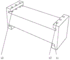
FIG. 5 is a schematic structural view of the pallet base of the present invention;
in the figure: 1. a pallet base; 11. a chute; 12. a first screw hole; 13. a second screw hole; 2. reinforcing ribs; 3. a joint base; 4. a buffer seat; 5. a fixed seat; 51. clamping a first rail; 6. a movable seat; 61. clamping a second rail; 7. a connecting seat; 8. a spring; 9. a roller; 10. a screw.
Detailed Description
The technical solutions in the embodiments of the present invention will be described clearly and completely with reference to the drawings in the embodiments of the present invention, and it is obvious that the described embodiments are only some embodiments of the present invention, not all embodiments. Based on the embodiments in the present invention, all other embodiments obtained by a person skilled in the art without creative work belong to the protection scope of the present invention.
In the description of the present invention, it should be noted that the terms "center", "upper", "lower", "left", "right", "vertical", "horizontal", "inner", "outer", and the like indicate orientations or positional relationships based on orientations or positional relationships shown in the drawings, and are only for convenience of description and simplification of description, but do not indicate or imply that the device or element referred to must have a specific orientation, be constructed and operated in a specific orientation, and thus, should not be construed as limiting the present invention. Furthermore, the terms "first," "second," and "third" are used for descriptive purposes only and are not to be construed as indicating or implying relative importance. In the description of the present invention, it is to be noted that, unless otherwise explicitly specified or limited, the terms "mounted", "connected" and "disposed" are to be construed broadly, and may be, for example, fixedly connected, detachably connected, or integrally connected; can be mechanically or electrically connected; they may be connected directly or indirectly through intervening media, or they may be interconnected between two elements. The specific meaning of the above terms in the present invention can be understood in specific cases to those skilled in the art. The following describes an embodiment of the present invention according to its overall structure.
Referring to fig. 1 to 5, in an embodiment of the present invention, an automotive suspension plate support structure includes a support plate seat 1, a reinforcing rib 2, a joint seat 3, and a cushion seat 4; the supporting plate seat 1 and the reinforcing rib 2, the reinforcing rib 2 and the connector seat 3 are fixedly connected with each other, one side of the supporting plate seat 1 is provided with a buffer seat 4, the buffer seat 4 comprises a fixed seat 5, a movable seat 6, a connecting seat 7 and a spring 8, the fixed seat 5 is movably connected with the supporting plate seat 1, the fixed seat 5 is movably connected with the movable seat 6, the connecting seat 7 is fixedly connected with the movable seat 6, and the spring 8 is movably connected with the movable seat 6.
As the utility model discloses further scheme again: the inside of fixing base 5 is provided with gyro wheel 9, and spout 11 has been seted up to the inside of layer board seat 1, and fixing base 5 is pegged graft with spout 11, and fixing base 5 and gyro wheel 9 roll connection, gyro wheel 9 and 11 sliding connection of spout.
As a further aspect of the present invention: one side of the fixed seat 5, which is far away from the pallet seat 1, is fixedly connected with a first clamping rail 51, one side of the movable seat 6, which is far away from the connecting seat 7, is fixedly connected with a second clamping rail 61, and the first clamping rail 51 is movably clamped with the second clamping rail 61.
As a further aspect of the present invention: one side of the supporting plate seat 1 is provided with a screw rod 10, a first screw hole 12 is formed in the supporting plate seat 1, a second screw hole 13 is formed in the sliding groove 11, the first screw hole 12 and the second screw hole 13 are both in threaded connection with the screw rod 10, and the fixing seat 5 is bolted with the supporting plate seat 1 through the idler wheels 9.
As a further aspect of the present invention: one end of the spring 8 is movably connected with the movable seat 6, and one end of the spring 8, which is far away from the movable seat 6, is movably connected with the supporting plate seat 1.
As a further aspect of the present invention: the buffer seat 4 is provided with two groups and is respectively arranged at two sides of the pallet seat 1.
As a further aspect of the present invention: the inside of connecting seat 7 is seted up the pilot hole of being connected with the suspension.
The utility model discloses a theory of operation is: because the plate support needs to be fixed when the suspension works, and the plate support can touch the ground to cause damage to the plate support when a vehicle jolts, the plate support is arranged to be of a buffering and damping structure, when the plate support is bumped due to vehicle jolts, the buffering and damping structure in the plate support can effectively buffer and damp the plate support, but the buffering and damping structure in the plate support is usually realized by adopting a spring, as is well known, although the spring can buffer and damp, the spring can be damaged after absorbing energy, just as the plate support for the automobile suspension is disclosed as CN201811221745.5, the spring can be damaged after absorbing energy, but the patent does not disclose how to maintain and replace the damaged spring, and the design that the spring cannot be replaced in the prior art leads to higher use, maintenance and replacement cost of the plate support;
after the screw rod 10 is screwed out of the second screw hole 13, the screw rod 10 penetrates out of the fixed seat 5 and then is screwed out of the first screw hole 12, then the buffer seat 4 is pulled out of the supporting plate seat 1 through the roller 9, the spring 8 in the buffer seat 4 can be replaced, the roller 9 can continuously roll in the process of pulling out the buffer seat 4, so that the buffer seat 4 can be smoothly pulled out, and the buffer seat 4 is prevented from being blocked;
when the plate support is bumped and collided, the connecting seat 7 is fixedly connected with the suspension, and the fixed seat 5 is movably connected with the movable seat 6, so that the impact force generated by collision is transmitted to the movable seat 6 by the connecting seat 7, the movable seat 6 extrudes the spring 8 and moves in the fixed seat 5, and the problem that the movable seat 6 is directly damaged due to impact can be avoided.
The above-mentioned, only be the concrete implementation of the preferred embodiment of the present invention, but the protection scope of the present invention is not limited thereto, and any person skilled in the art is in the technical scope of the present invention, according to the technical solution of the present invention and the utility model, the concept of which is equivalent to replace or change, should be covered within the protection scope of the present invention.
Claims (7)
1. An automobile suspension plate support structure comprises a support plate seat (1), a reinforcing rib (2), a joint seat (3) and a buffer seat (4); the method is characterized in that: the supporting plate is characterized in that the supporting plate seat (1) is fixedly connected with the reinforcing rib (2), the reinforcing rib (2) and the joint seat (3) mutually, a buffer seat (4) is arranged on one side of the supporting plate seat (1), the buffer seat (4) comprises a fixed seat (5), a movable seat (6), a connecting seat (7) and a spring (8), the fixed seat (5) is movably connected with the supporting plate seat (1), the fixed seat (5) is movably connected with the movable seat (6), the connecting seat (7) is fixedly connected with the movable seat (6), and the spring (8) is movably connected with the movable seat (6).
2. The vehicle suspension plate support structure according to claim 1, wherein a roller (9) is disposed inside the fixing seat (5), a sliding groove (11) is disposed inside the support plate seat (1), the fixing seat (5) is inserted into the sliding groove (11), the fixing seat (5) is connected to the roller (9) in a rolling manner, and the roller (9) is connected to the sliding groove (11) in a sliding manner.
3. The vehicle suspension plate support structure according to claim 2, wherein a first clamping rail (51) is fixedly connected to one side of the fixed seat (5) away from the support plate seat (1), a second clamping rail (61) is fixedly connected to one side of the movable seat (6) away from the connecting seat (7), and the first clamping rail (51) is movably clamped with the second clamping rail (61).
4. The automobile suspension plate support structure according to claim 3, wherein a screw (10) is arranged on one side of the support plate seat (1), a first screw hole (12) is formed in the support plate seat (1), a second screw hole (13) is formed in the sliding groove (11), the first screw hole (12) and the second screw hole (13) are both in threaded connection with the screw (10), and the fixed seat (5) is bolted with the support plate seat (1) through a roller (9).
5. The automobile suspension plate support structure according to claim 4, wherein one end of the spring (8) is movably connected with the movable seat (6), and one end of the spring (8) far away from the movable seat (6) is movably connected with the supporting plate seat (1).
6. The vehicle suspension plate carrier structure according to claim 5, wherein the cushion seat (4) is provided in two groups and is divided on both sides of the plate carrier (1).
7. The vehicle suspension plate support structure according to claim 6, wherein the connecting base (7) has an assembling hole formed therein for connecting with a suspension.
Priority Applications (1)
| Application Number | Priority Date | Filing Date | Title |
|---|---|---|---|
| CN202223083892.5U CN218839092U (en) | 2022-11-21 | 2022-11-21 | Automobile suspension plate support structure |
Applications Claiming Priority (1)
| Application Number | Priority Date | Filing Date | Title |
|---|---|---|---|
| CN202223083892.5U CN218839092U (en) | 2022-11-21 | 2022-11-21 | Automobile suspension plate support structure |
Publications (1)
| Publication Number | Publication Date |
|---|---|
| CN218839092U true CN218839092U (en) | 2023-04-11 |
Family
ID=87303085
Family Applications (1)
| Application Number | Title | Priority Date | Filing Date |
|---|---|---|---|
| CN202223083892.5U Active CN218839092U (en) | 2022-11-21 | 2022-11-21 | Automobile suspension plate support structure |
Country Status (1)
| Country | Link |
|---|---|
| CN (1) | CN218839092U (en) |
-
2022
- 2022-11-21 CN CN202223083892.5U patent/CN218839092U/en active Active
Similar Documents
| Publication | Publication Date | Title |
|---|---|---|
| CN103568809B (en) | A kind of limit-type engine mounting assembly of bracket | |
| CN210851925U (en) | Spring shock absorption mechanism for automobile | |
| CN210950671U (en) | Computer mainframe damping base | |
| CN218839092U (en) | Automobile suspension plate support structure | |
| CN201487106U (en) | Plate spring device | |
| CN210371781U (en) | Shock absorber and shock attenuation equipment and haulage vehicle that remove on-vehicle mass spectrograph | |
| CN210363534U (en) | Plug-in type vehicle-mounted shelter damping device | |
| CN210760137U (en) | Automobile front pillar assembly and vehicle | |
| CN210125987U (en) | Mounting support for mechanical grinding machine | |
| CN211336262U (en) | Electric bicycle shock attenuation back seat | |
| CN210191072U (en) | Adjustable automobile shock absorber mounting bracket | |
| CN205101448U (en) | Modular bumper shock absorber subassembly | |
| CN206606129U (en) | It is a kind of to put the stable Vehicular luggage rack of article | |
| CN215171827U (en) | Damping device for building structure | |
| CN210555128U (en) | Reinforcing support for automobile chassis brake | |
| CN218839573U (en) | Car reinforcing plate convenient to installation | |
| CN216545610U (en) | Air suspension air bag protective cover | |
| CN213167624U (en) | Supporting plate structure of automobile suspension | |
| CN213921362U (en) | Frame structure of five-way beam | |
| CN215706292U (en) | Electric flat carriage with damping function | |
| CN213451457U (en) | Automobile chassis shock absorber support | |
| CN217945058U (en) | High-bearing automobile luggage rack | |
| CN219096995U (en) | Unmanned aerial vehicle that stability is good | |
| CN217623943U (en) | Elastic damping mechanism for tricycle frame | |
| CN210633873U (en) | Novel coupling vibration of concrete mixer car axle device |
Legal Events
| Date | Code | Title | Description |
|---|---|---|---|
| GR01 | Patent grant | ||
| GR01 | Patent grant |