CN210760137U - Automobile front pillar assembly and vehicle - Google Patents
Automobile front pillar assembly and vehicle Download PDFInfo
- Publication number
- CN210760137U CN210760137U CN201921202483.8U CN201921202483U CN210760137U CN 210760137 U CN210760137 U CN 210760137U CN 201921202483 U CN201921202483 U CN 201921202483U CN 210760137 U CN210760137 U CN 210760137U
- Authority
- CN
- China
- Prior art keywords
- spring
- plate
- hole
- spring seat
- front pillar
- Prior art date
- Legal status (The legal status is an assumption and is not a legal conclusion. Google has not performed a legal analysis and makes no representation as to the accuracy of the status listed.)
- Active
Links
Images

Abstract
The utility model relates to an automobile front pillar assembly and vehicle, this automobile front pillar assembly include bumper shock absorber body and Z style of calligraphy spring. The shock absorber body includes a shock absorber cylinder, a piston rod, a first spring seat and a second spring seat. The piston rod is slidably inserted into the damper cylinder. The first spring seat is fixedly arranged on the piston rod, and the second spring seat is fixedly arranged on the shock absorber cylinder. The Z-shaped spring is sleeved on the piston rod and the shock absorber cylinder, and two ends of the Z-shaped spring are respectively abutted against the first spring seat and the second spring seat. Because the distance between three plates forming the Z-shaped spring is larger, and the plates are connected in an angle manner, when the Z-shaped spring is impacted, the angle between the plates is reduced to absorb the impact, and the plates cannot be contacted with each other, so that the Z-shaped spring cannot generate abnormal sound when the Z-shaped spring is impacted.
Description
Technical Field
The disclosure relates to the technology of automotive chassis suspension, in particular to an automotive front pillar assembly and a vehicle.
Background
The front pillar assembly of the automobile functions to elastically connect the wheel knuckle with the vehicle body and to alleviate road impact. The front strut assembly of the existing automobile is composed of a shock absorber assembly, a front spiral spring, a front strut buffer block, a spiral spring upper seat, a bearing and a fixing nut. The spiral spring is an important component of the front pillar assembly and is used for buffering acting force transmitted to a frame by the wheel and playing a role in shock absorption.
At present, the front pillars of the automobile generally adopt spiral springs which are formed by winding, and spring wires are easy to be wound during working, so that abnormal sound is generated.
SUMMERY OF THE UTILITY MODEL
An object of the present disclosure is to provide an automotive front pillar assembly that can alleviate road surface impact and is less likely to generate abnormal noise.
In order to achieve the above object, the present disclosure provides an automobile front pillar assembly, which includes a shock absorber body and a Z-shaped spring, wherein the shock absorber body includes a shock absorber cylinder, a piston rod, a first spring seat and a second spring seat, the piston rod is slidably inserted into the shock absorber cylinder, the first spring seat is fixedly disposed on the piston rod, the second spring seat is fixedly disposed on the shock absorber cylinder, the Z-shaped spring is sleeved on the piston rod and the shock absorber cylinder, and two ends of the Z-shaped spring are respectively abutted to the first spring seat and the second spring seat.
Optionally, the Z-shaped spring includes a first flat plate, a second flat plate, and a connecting plate, the first flat plate and the second flat plate are arranged in parallel, the connecting plate is connected between the first flat plate and the second flat plate in an inclined manner, a first abutting plane is arranged on one side of the first spring seat facing the second spring seat, a second abutting plane is arranged on one side of the second spring seat facing the first spring seat, and the first flat plate and the second flat plate abut against the first abutting plane and the second abutting plane respectively.
Optionally, an included angle between the first flat plate and the connecting plate is 30-40 °, and an included angle between the second flat plate and the connecting plate is 30-40 °.
Optionally, the first flat plate and the connecting plate are connected through a first arc connecting portion, and the second flat plate and the connecting plate are connected through a second arc connecting portion.
Optionally, the first flat plate is provided with a first through hole, the second flat plate is provided with a second through hole, the connecting plate is provided with a third through hole, and the Z-shaped spring is sleeved on the piston rod and the shock absorber cylinder through the first through hole, the second through hole and the third through hole.
Optionally, the third through hole is a long hole extending along a length direction of the connecting plate, one of the first through hole and the second through hole is a long hole extending along a length direction of the corresponding flat plate, and the other is a round hole.
Optionally, the first through hole is opened in the middle of the first flat plate, and the second through hole is opened in the middle of the second flat plate.
Optionally, a vibration isolation cushion is arranged between the zigzag spring and the first spring seat.
Optionally, the material of the zigzag spring is spring steel.
According to another aspect of the present disclosure, a vehicle is also provided, which includes the automotive front pillar assembly.
Through above-mentioned technical scheme, when car front pillar assembly was installed in the vehicle, Z style of calligraphy spring was compression state butt between first spring holder and second spring holder to can be through the deformation of Z style of calligraphy spring in order to absorb from the road surface impact, play the cushioning effect. For the technical scheme who adopts coil spring among the prior art, because there is not the spring coil among the coil spring among the Z style of calligraphy structure of Z style of calligraphy spring, the interval is great between three plates of constituteing Z style of calligraphy spring, and connect with being the angle between the plate, when receiving the impact force, the angle between the plate diminishes in order to absorb the impact, can not contact each other between the plate, consequently, when receiving the impact, Z style of calligraphy spring can not produce abnormal sound.
Additional features and advantages of the disclosure will be set forth in the detailed description which follows.
Drawings
The accompanying drawings, which are included to provide a further understanding of the disclosure and are incorporated in and constitute a part of this specification, illustrate embodiments of the disclosure and together with the description serve to explain the disclosure without limiting the disclosure. In the drawings:
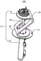
FIG. 1 is a schematic perspective view of an automotive front pillar assembly according to an embodiment of the present disclosure;
FIG. 2 is a front view of an automotive front pillar assembly according to one embodiment of the present disclosure;
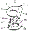
fig. 3 is a schematic perspective view of a zigzag spring according to an embodiment of the present disclosure.
Description of the reference numerals
100-an automotive front pillar assembly; 10-a damper body; a 20-Z shaped spring; 21-a first plate; 211 — a first via; 22-a second plate; 221-a second via; 23-a connecting plate; 231-third via holes; 24-a first arc connecting part; 25-a second arc connection; 30-a damper cylinder; 40-a piston rod; 50-a first spring seat; 51-a first abutment plane; 60-a second spring seat; 61-second abutment plane.
Detailed Description
The following detailed description of specific embodiments of the present disclosure is provided in connection with the accompanying drawings. It should be understood that the detailed description and specific examples, while indicating the present disclosure, are given by way of illustration and explanation only, not limitation.
In the present disclosure, unless otherwise specified, the use of the directional terms such as "up and down" generally means "up and down" in a state where the front pillar assembly of the automobile is mounted on the vehicle, and the direction coincides with the direction of "up and down" when the vehicle is normally running. In addition, the terms "first", "second", "third", and the like used in the embodiments of the present disclosure are for distinguishing one element from another, and have no order or importance.
As shown in fig. 1-3, in accordance with one aspect of the present disclosure, an automotive front pillar assembly 100 is provided. Which includes a shock absorber body 10 and a zigzag spring 20. The shock absorber body 10 includes a shock absorber tube 30, a piston rod 40, a first spring seat 50 and a second spring seat 60, the piston rod 40 is slidably inserted into the shock absorber tube 30, the first spring seat 50 is fixedly disposed on the piston rod 40, the second spring seat 60 is fixedly disposed on the shock absorber tube 30, the Z-shaped spring 20 is sleeved on the piston rod 40 and the shock absorber tube 30, and two ends of the Z-shaped spring 20 are respectively abutted against the first spring seat 50 and the second spring seat 60.
With the above arrangement, when the automotive front pillar assembly 100 is mounted on a vehicle, the zigzag spring 20 is in a compressed state and is in contact with the first spring seat 50 and the second spring seat 60, so that the zigzag spring 20 can deform to absorb road impact, thereby achieving a cushioning effect. For the technical scheme who adopts coil spring among the prior art, because there is not the spring coil among the coil spring in the Z style of calligraphy structure of Z style of calligraphy spring 20, the interval is great between three plates of constituteing Z style of calligraphy spring, and connect to be the angle between the plate, when receiving the impact force, the angle between the plate diminishes in order to absorb the impact, can not contact each other between the plate, consequently, when receiving the impact, Z style of calligraphy spring 20 can not produce abnormal sound.
At present, the front pillars of the automobile generally adopt the spiral springs, and the ends of the spiral springs are not flat due to winding forming during manufacturing of the spiral springs, so that the front pillars of the automobile can not be in effective contact with the spring seats. The end head is uneven and unbalanced in stress, and abnormal sound can be generated at the contact surface of the end head and the spring seat. And because the stress area of the spiral spring is small, the impact force cannot be dispersed rapidly when being buffered, the impact pressure is high, and the abrasion is easy to generate at the contact surface.
In order to smoothly buffer the impact force, as shown in fig. 3, the zigzag spring 20 may include a first plate 21, a second plate 22, and a connection plate 23. The first plate 21 and the second plate 22 are arranged in parallel. The connecting plate 23 is connected obliquely between the first plate 21 and the second plate 22. A first abutting flat surface 51 is provided on a side of the first spring seat 50 facing the second spring seat 60, a second abutting flat surface 61 is provided on a side of the second spring seat 60 facing the first spring seat 50, and the first flat plate 21 and the second flat plate 22 abut against the first abutting flat surface 51 and the second abutting flat surface 61, respectively.
The automobile front pillar assembly 100 in the present disclosure employs the Z-shaped spring 20, and the first plate 21 and the second plate 22 are in planar contact with the first spring seat 50 and the second spring seat 60, respectively, so that the force-receiving area can be significantly increased, when receiving an impact force, the impact force can be rapidly transmitted to the Z-shaped spring 20, and the Z-shaped spring 20 is deformed to buffer the impact force, thereby improving the shock absorption effect of the automobile front pillar assembly 100 and improving the comfort of the vehicle. The zigzag spring 20 is a bent plate-shaped structure, and the width of the zigzag spring is much larger than the diameter of the coil spring, so that a larger elastic force can be stored.
Further, as shown in FIG. 3, the angle between the first plate 21 and the web 23 may be approximately 30-40, and the angle between the second plate 22 and the web 23 may be approximately 30-40. Therefore, the Z-shaped spring 20 can be ensured to have enough rigidity to meet the shock absorption requirement of the automobile front pillar assembly 100, and the first flat plate 21, the second flat plate 22 and the connecting plate 23 can be ensured to have enough distance, so that the Z-shaped spring 20 cannot collide with each other to generate abnormal sound after being compressed. Furthermore, it is convenient that the first plate 21 and the second plate 22 are aligned with each other in the vertical direction so as to be sleeved on the piston rod 40. It should be noted that the specific values of the included angle between the first plate 21 and the connecting plate 23 and the included angle between the second plate 22 and the connecting plate 23 are not limited in the present disclosure, and may be any suitable angle as long as a sufficient distance between the connecting plate and the first plate 21 and the second plate 22 can be ensured.
As shown in fig. 3, the first plate 21 and the connecting plate 23 are connected by a first arc connecting portion 24, and the second plate 22 and the connecting plate 23 are connected by a second arc connecting portion 25. The first flat plate 21, the second flat plate 22 and the connecting plate 23 are connected in a smooth transition manner through the first arc connecting portion 24 and the second arc connecting portion 25, so that stress concentration at the connecting position can be avoided, the Z-shaped spring 20 has enough strength as a whole, and the Z-shaped spring is not easy to damage when buffering impact force.
The first plate 21 has a first through hole 211, the second plate 22 has a second through hole 221, and the connecting plate 23 has a third through hole 231. The zigzag spring 20 is sleeved on the piston rod 40 and the shock absorber tube 30 through the first through hole 211, the second through hole 221 and the third through hole 231, so that the zigzag spring 20 can be conveniently and stably fixed to the shock absorber body 10.
As shown in fig. 3, in one embodiment of the present disclosure, the third through hole 231 is a long hole extending in the length direction of the connection plate 23, one of the first through hole 211 and the second through hole 221 is a long hole (specifically, may be a waist-shaped hole) extending in the length direction of the flat plate, and the other is a circular hole. The longitudinal direction is a direction a in fig. 3.
As shown in FIG. 1, during installation, the circular hole in the zigzag spring 20 is fitted over the damper cylinder 30. By providing the long holes in the zigzag springs 20, the weight of the zigzag springs 20 can be effectively reduced. The combination of the round hole and the long hole can reduce the assembly requirement and the machining precision requirement.
Further, as shown in fig. 3, the first through hole 211 may be opened in the middle of the first plate 21, and the second through hole 221 may be opened in the middle of the second plate 22, so that the force applied to each position of the first plate 21 and the second plate 22 may be uniformly applied, and the applied impact force may be rapidly dispersed.
In order to reduce wear between the zigzag spring 20 and the first spring seat 50, in one embodiment of the present disclosure, a vibration isolation pad (not shown) may be disposed between the zigzag spring 20 and the first spring seat 50. Specifically, as shown in fig. 2, the vibration-isolating pad may be disposed between the first flat plate 51 and the first abutment flat surface 51 of the first spring seat 50. Rigid contact between the Z-shaped spring 20 and the first spring seat 50 can be avoided by arranging the shock insulation pad, so that abrasion between the Z-shaped spring 20 and the first spring seat 50 can be reduced, and impact force can be further buffered. Wherein, the shock insulation cushion can adopt a rubber cushion.
In the present disclosure, the material of the zigzag spring 20 is not limited. In one embodiment of the present disclosure, the material of the zigzag spring 20 may be spring steel. The spring steel has excellent comprehensive performance, particularly has excellent elastic limit, strength limit and yield ratio, so that the Z-shaped spring 20 can store larger elastic potential energy, is not easy to damage and has long service life.
In another aspect of the present disclosure, a vehicle is also provided. The vehicle includes the automotive front pillar assembly 100 described above. Specifically, the vehicle includes a frame and a chassis with a knuckle mounted thereto, and the above-described automotive front pillar assembly 100 is connected between the frame and the chassis. The front pillar assembly 100 elastically connects the chassis and the frame, and plays a role in buffering road impact, thereby improving the riding comfort of the vehicle.
The preferred embodiments of the present disclosure are described in detail with reference to the accompanying drawings, however, the present disclosure is not limited to the specific details of the above embodiments, and various simple modifications may be made to the technical solution of the present disclosure within the technical idea of the present disclosure, and these simple modifications all belong to the protection scope of the present disclosure.
It should be noted that, in the foregoing embodiments, various features described in the above embodiments may be combined in any suitable manner, and in order to avoid unnecessary repetition, various combinations that are possible in the present disclosure are not described again.
In addition, any combination of various embodiments of the present disclosure may be made, and the same should be considered as the disclosure of the present disclosure, as long as it does not depart from the spirit of the present disclosure.
Claims (10)
1. The automobile front pillar assembly is characterized by comprising a shock absorber body (10) and a Z-shaped spring (20), wherein the shock absorber body (10) comprises a shock absorber cylinder (30), a piston rod (40), a first spring seat (50) and a second spring seat (60), the piston rod (40) is slidably inserted into the shock absorber cylinder (30), the first spring seat (50) is fixedly arranged on the piston rod (40), the second spring seat (60) is fixedly arranged on the shock absorber cylinder (30), the Z-shaped spring (20) is sleeved on the piston rod (40) and the shock absorber cylinder (30), and two ends of the Z-shaped spring (20) are respectively abutted to the first spring seat (50) and the second spring seat (60).
2. The automotive front pillar assembly according to claim 1, characterized in that the zigzag spring (20) includes a first flat plate (21), a second flat plate (22), and a connecting plate (23), the first flat plate (21) and the second flat plate (22) are arranged in parallel, the connecting plate (23) is connected obliquely between the first flat plate (21) and the second flat plate (22), a first abutting plane (51) is provided on a side of the first spring seat (50) facing the second spring seat (60), a second abutting plane (61) is provided on a side of the second spring seat (60) facing the first spring seat (50), and the first flat plate (21) and the second flat plate (22) abut against the first abutting plane (51) and the second abutting plane (61), respectively.
3. Automotive front pillar assembly according to claim 2, characterised in that the angle between the first plate (21) and the web (23) is between 30 ° and 40 ° and the angle between the second plate (22) and the web (23) is between 30 ° and 40 °.
4. The automotive front pillar assembly according to claim 2, characterized in that the first plate (21) and the connecting plate (23) are connected by a first circular arc connecting portion (24), and the second plate (22) and the connecting plate (23) are connected by a second circular arc connecting portion (25).
5. The automotive front pillar assembly according to claim 2, wherein the first plate (21) is provided with a first through hole (211), the second plate (22) is provided with a second through hole (221), the connecting plate (23) is provided with a third through hole (231), and the zigzag spring (20) is sleeved on the piston rod (40) and the shock absorber tube (30) through the first through hole (211), the second through hole (221) and the third through hole (231).
6. The automotive front pillar assembly according to claim 5, characterized in that the third through hole (231) is a long hole extending in a length direction of the connecting plate (23), one of the first through hole (211) and the second through hole (221) is a long hole extending in a length direction of the corresponding panel (21, 22), and the other is a circular hole.
7. The automotive front pillar assembly according to claim 5, characterized in that the first through hole (211) opens in the middle of the first plate (21) and the second through hole (221) opens in the middle of the second plate (22).
8. The automotive front pillar assembly according to any one of claims 1-7, characterized in that a vibration isolation cushion is provided between the zigzag spring (20) and the first spring seat (50).
9. Automotive front pillar assembly according to any one of claims 1-7, characterised in that the material of the zigzag spring (20) is spring steel.
10. A vehicle, characterized by comprising an automotive front pillar assembly (100) according to any one of claims 1-9.
Priority Applications (1)
| Application Number | Priority Date | Filing Date | Title |
|---|---|---|---|
| CN201921202483.8U CN210760137U (en) | 2019-07-26 | 2019-07-26 | Automobile front pillar assembly and vehicle |
Applications Claiming Priority (1)
| Application Number | Priority Date | Filing Date | Title |
|---|---|---|---|
| CN201921202483.8U CN210760137U (en) | 2019-07-26 | 2019-07-26 | Automobile front pillar assembly and vehicle |
Publications (1)
| Publication Number | Publication Date |
|---|---|
| CN210760137U true CN210760137U (en) | 2020-06-16 |
Family
ID=71031626
Family Applications (1)
| Application Number | Title | Priority Date | Filing Date |
|---|---|---|---|
| CN201921202483.8U Active CN210760137U (en) | 2019-07-26 | 2019-07-26 | Automobile front pillar assembly and vehicle |
Country Status (1)
| Country | Link |
|---|---|
| CN (1) | CN210760137U (en) |
Cited By (1)
| Publication number | Priority date | Publication date | Assignee | Title |
|---|---|---|---|---|
| CN113561721A (en) * | 2021-07-30 | 2021-10-29 | 北京长安汽车工程技术研究有限责任公司 | Shock absorber assembly capable of adjusting vehicle height and vehicle |
-
2019
- 2019-07-26 CN CN201921202483.8U patent/CN210760137U/en active Active
Cited By (2)
| Publication number | Priority date | Publication date | Assignee | Title |
|---|---|---|---|---|
| CN113561721A (en) * | 2021-07-30 | 2021-10-29 | 北京长安汽车工程技术研究有限责任公司 | Shock absorber assembly capable of adjusting vehicle height and vehicle |
| CN113561721B (en) * | 2021-07-30 | 2023-12-08 | 北京长安汽车工程技术研究有限责任公司 | Shock absorber assembly capable of adjusting vehicle height and vehicle |
Similar Documents
| Publication | Publication Date | Title |
|---|---|---|
| CN107415616B (en) | Transverse composite material leaf spring suspension structure | |
| CN201225381Y (en) | Suspension fork rubber shock-absorbing pad for commercial vehicle | |
| CN210760137U (en) | Automobile front pillar assembly and vehicle | |
| KR101154776B1 (en) | Rear suspension system for vehicle | |
| CN210113163U (en) | Front suspension system of heavy truck cab | |
| CN211390868U (en) | Vehicle frame limiting block | |
| CN211259445U (en) | Automobile shock absorber and suspension | |
| US8517456B1 (en) | Cab suspension member for terminal tractors | |
| CN201193671Y (en) | Interactive rubber cushion | |
| CN212353513U (en) | Front suspension device and vehicle with same | |
| CN215444877U (en) | Structure-reinforced automobile rubber shock-absorbing block | |
| CN204878494U (en) | Two rings rear damper of a big section of thick bamboo | |
| CN217713466U (en) | Front shock absorber of electric four-wheel passenger vehicle | |
| CN220281495U (en) | Anti-torsion frame assembly | |
| CN205059172U (en) | Electric automobile mounting structure | |
| CN110696578B (en) | Variable-rigidity third damping suspension for equation racing vehicle | |
| CN219903971U (en) | Rear suspension system of electric commercial vehicle | |
| CN210555128U (en) | Reinforcing support for automobile chassis brake | |
| CN215334143U (en) | Novel automobile noise reduction shock absorber | |
| CN216518272U (en) | Generator set chassis | |
| CN209977154U (en) | Automobile noise reduction shock absorber | |
| CN217207474U (en) | Automobile front shock absorber | |
| CN213776192U (en) | Damping device and wheel set | |
| CN217270705U (en) | A vibration damper and inflating pump assembly for installing inflating pump | |
| CN113027727B (en) | Compressor suspension support of doublestage vibration isolation |
Legal Events
| Date | Code | Title | Description |
|---|---|---|---|
| GR01 | Patent grant | ||
| GR01 | Patent grant |