CN218531212U - Feed ingredient rubbing crusher - Google Patents
Feed ingredient rubbing crusher Download PDFInfo
- Publication number
- CN218531212U CN218531212U CN202222752996.4U CN202222752996U CN218531212U CN 218531212 U CN218531212 U CN 218531212U CN 202222752996 U CN202222752996 U CN 202222752996U CN 218531212 U CN218531212 U CN 218531212U
- Authority
- CN
- China
- Prior art keywords
- wall
- driving motor
- crushing
- switch
- case
- Prior art date
- Legal status (The legal status is an assumption and is not a legal conclusion. Google has not performed a legal analysis and makes no representation as to the accuracy of the status listed.)
- Active
Links
Images


Abstract
The utility model discloses a feed ingredient rubbing crusher relates to feed ingredient processing technology field, including smashing the case, the equal sliding connection of inner wall of smashing the case both sides has two fly leafs, all rotates through the bearing between per two relative fly leafs to be connected with crushing roller, and the equal fixed roll body that is equipped with in surface of two crushing rollers, the equal fixed blade that is equipped with a plurality of equidistance setting in surface of two roll bodies is equipped with adjusting part between two fly leafs with one side, the beneficial effects of the utility model are that: the two-way screw rod is driven to rotate by starting the second driving motor, the two-way screw rod rotates to enable every two opposite movable plates to move relatively along the inner walls of the two first sliding grooves respectively, the two movable plates move to drive the two crushing shafts to move relatively, and then the distance between the two roller bodies in the crusher is adjusted by a worker conveniently, so that the crusher is suitable for feeds with different crushing degrees, and the practicability of the crusher is effectively improved.
Description
Technical Field
The utility model relates to a rubbing crusher, in particular to feedstuff rubbing crusher belongs to feedstuff processing technology field.
Background
Animal feed is prepared by deep processing a series of raw materials, the raw materials need to be ground and milled before mixing and batching, at the moment, a feed raw material grinder is needed to grind, the grinder is a machine for grinding large-size solid raw materials into required sizes, and the grinder is widely applied to various departments such as mines, smelting, building materials, roads, railways, water conservancy, chemical industries and the like.
The feed raw material pulverizer disclosed by the application number of CN201920810426.1 is also an increasingly mature technology, and comprises a pulverizer case, wherein a crushing mechanism is arranged inside the pulverizer case, and a blowing mechanism for blowing air to the interior of the pulverizer case is arranged outside the pulverizer case; the blowing mechanism comprises an air storage tank arranged on the outer wall of the crusher case and a plurality of air nozzles arranged on the lower portions of the side walls of the two sides of the crusher case, and the air storage tank is connected with the air nozzles through pipelines. The utility model provides a pair of feed ingredient rubbing crusher, its structure is ingenious, and feed ingredient rolls at the roll of tumbling in the rubbing crusher incasement under the effect of jetting mechanism, is smashed repeatedly by crushed aggregates mechanism, has improved feed ingredient's crushing effect greatly, but the device still has following defect when in-service use.
1) The crusher cannot adjust the hammer pieces according to the crushing degree required by the feed raw materials in the using process, so that the crusher has poor applicability and cannot treat feeds with different crushing degrees;
2) This rubbing crusher can't adjust the feeding volume according to the work efficiency of machine itself in the use, when the fodder drops into organism in a large number and smashes, very easily causes rubbing crusher to construct the jam.
SUMMERY OF THE UTILITY MODEL
An object of the utility model is to provide a feedstuff pulverizer to the crushing degree that can't be required according to the fodder that provides in solving above-mentioned background art is adjusted, can't be according to the problem of the work efficiency adjustment feeding volume of machine itself.
In order to achieve the above object, the utility model provides a following technical scheme: the utility model provides a feed ingredient rubbing crusher, is including smashing the case, the equal sliding connection of inner wall of smashing the case both sides has two fly leafs, per two is relative all rotate through the bearing between the fly leaf and be connected with crushing roller, two the equal fixed roll body that is equipped with in surface of crushing roller, two the equal fixed blade that is equipped with a plurality of equidistance setting in surface of roll body is with two of one side be equipped with adjusting part between the fly leaf, the top of smashing the case is equipped with accuse stream subassembly, the top of smashing the case articulates there is the apron, the fixed feeder hopper that is equipped with in inner wall at apron top middle part, with two of one side of fly leaf one side is all fixed and is equipped with a driving motor, two a driving motor's transmission shaft respectively with the one end fixed connection of two crushing roller.
Preferably, the adjusting part includes two-way lead screws, four screw-nut and two first spouts, two the two-way lead screw all rotates the inner wall of connection in crushing case front both sides respectively through the bearing, two the equal threaded connection in both sides of two-way lead screw has screw-nut, four screw-nut is fixed the inner wall that sets up at four fly leafs respectively, two first spout is seted up respectively at the inner wall of crushing case both sides bottom, two first spout respectively with two with one side fly leaf sliding connection.
Preferably, the crushing case is fixed on one side of the front face and is provided with a second driving motor, a transmission shaft of the second driving motor is fixedly connected with one end of one of the two-way screw rods, belt pulleys are fixedly arranged on the surfaces of the two-way screw rods, and a linkage belt is connected between the belt pulleys in a transmission manner.
Preferably, the flow control assembly comprises an extension plate, an electric push rod, two second sliding grooves, a flow control plate and a material passing groove, the extension plate is fixedly arranged at the top of one side of the crushing box, the electric push rod is fixedly arranged at one side of the top end of the extension plate, the two second sliding grooves are respectively arranged on the inner walls of the tops of the two sides of the crushing box, the flow control plate is connected between the two second sliding grooves in a sliding mode and fixedly connected with the push rod of the electric push rod, and the material passing groove is formed in the inner wall of the middle of the flow control plate.
Preferably, the middle part of smashing the case opposite side is fixed and is equipped with the dust collection bin, the fixed air-blower that is equipped with of inner wall of dust collection bin one side, it leads to the silo to have seted up between dust collection bin and the crushing case, the inside of the inner wall that leads to the silo and feeder hopper all is fixed and is equipped with the filter screen, the air-blast end of air-blower is fixed and is equipped with the dust screen, the dust exhaust hole has been seted up to the bottom of dust collection bin inner wall, the discharge opening has been seted up to the bottom of crushing case one side, the equal threaded connection of inner wall in inner wall and the dust exhaust hole of discharge opening has sealed lid.
Preferably, two the inner wall of the positive both sides of first spout all fixedly is equipped with reset spring, four reset spring's one end all fixedly is equipped with the baffle, four the baffle respectively with four fly leaf fixed connection.
Preferably, smash the positive top of case and fix and be equipped with flush mounting plate of switch, flush mounting plate of switch's surface is equipped with first driving motor switch, second driving motor switch, electric putter switch and air-blower switch respectively, two first driving motor, second driving motor, electric putter and air-blower are respectively through first driving motor switch, second driving motor switch, electric putter switch and air-blower switch and power electric connection.
Compared with the prior art, the utility model provides a pair of feed ingredient rubbing crusher has following beneficial effect:
1. the two-way screw rod is driven to rotate by starting a second driving motor, and the two-way screw rod rotates at the same speed due to the fact that a linkage belt is in transmission connection with the two belt pulleys, so that each two opposite movable plates respectively move along the inner walls of the two first sliding grooves in a relative mode due to the rotation of the two-way screw rods, and the two movable plates move to drive the two crushing shafts to move in a relative mode, so that a worker can conveniently adjust the distance between the two roller bodies in the crusher, the crusher is suitable for feeds with different crushing degrees, and the practicability of the crusher is effectively improved;
2. the flow control plate slides between the two second sliding grooves by extending the push rod of the electric push rod, and the flow gap between the feed through groove and the feed hopper is gradually reduced in the sliding process of the flow control plate, so that the feed blanking speed of the feed can be adjusted according to the working efficiency of the pulverizer, and the interior of the pulverizer is prevented from being blocked;
3. the operation of the blower can lead dust and impurities to be filtered into the dust collecting bin through the dust screen, thereby effectively improving the quality of the crushed feed raw materials.
Drawings
Fig. 1 is a schematic structural view of the present invention;
fig. 2 is one of the schematic sectional structural diagrams of the present invention;
fig. 3 is a second schematic cross-sectional view of the present invention;
fig. 4 is an enlarged schematic view of a portion a of fig. 2 according to the present invention;
fig. 5 is an enlarged schematic structural diagram of fig. 2B according to the present invention.
In the figure: 1. a crushing box; 2. a movable plate; 3. a crushing shaft; 4. a roller body; 5. a blade; 6. an adjustment assembly; 7. a flow control assembly; 8. a cover plate; 9. a feed hopper; 10. a dust collection bin; 11. a feed through hole; 12. filtering with a screen; 13. a return spring; 14. a baffle plate; 15. a switch panel; 16. a first drive motor; 17. a dust exhaust hole; 18. a discharge hole; 19. a sealing cover; 20. a blower; 61. a bidirectional screw rod; 62. a feed screw nut; 63. a first chute; 611. a second drive motor; 612. a belt pulley; 613. a linkage belt; 71. an extension plate; 72. an electric push rod; 73. a second chute; 74. a flow control plate; 75. and (4) feeding a trough.
Detailed Description
The technical solutions in the embodiments of the present invention will be described clearly and completely with reference to the accompanying drawings in the embodiments of the present invention, and it is obvious that the described embodiments are only some embodiments of the present invention, not all embodiments. Based on the embodiments in the present invention, all other embodiments obtained by a person skilled in the art without creative work belong to the protection scope of the present invention.
Example 1:
referring to fig. 1-5, the utility model provides a feed raw material crusher, including crushing case 1, the inner wall of crushing case 1 both sides all sliding connection has two fly leaves 2, every two relative fly leaves 2 all connect with crushing roller 3 through the bearing rotation, the surface of two crushing roller 3 all fixes and is equipped with roll body 4, the surface of two roll body 4 all fixes and is equipped with a plurality of equidistance blade 5 that sets up, be equipped with adjusting part 6 between two fly leaves 2 of the same side, the top of crushing case 1 is equipped with flow control part 7, the top of crushing case 1 articulates there is apron 8, the inner wall in the middle part of apron 8 top is fixed and is equipped with feeder hopper 9, one side of two fly leaves 2 of the same side all fixes and is equipped with first drive motor 16, the transmission shaft of two first drive motors 16 respectively with the one end fixed connection of two crushing roller 3;
a dust collecting bin 10 is fixedly arranged in the middle of the other side of the crushing box 1, an air blower 20 is fixedly arranged on the inner wall of one side of the dust collecting bin 10, a material passing hole 11 is formed between the dust collecting bin 10 and the crushing box 1, a filter screen 12 is fixedly arranged on the inner wall of the material passing hole 11 and the inside of the feed hopper 9, a dust screen is fixedly arranged on the air blowing end of the air blower 20, a dust discharging hole 17 is formed in the bottom end of the inner wall of the dust collecting bin 10, a material discharging hole 18 is formed in the bottom end of one side of the crushing box 1, a sealing cover 19 is in threaded connection with the inner wall of the material discharging hole 18 and the inner wall of the dust discharging hole 17, and dust and impurities can be filtered into the dust collecting bin 10 through the dust screen by the operation of the air blower 20, so that the quality of crushed feed raw materials is improved;
referring to fig. 1-5, a feed raw material pulverizer further comprises an adjusting assembly 6, wherein the adjusting assembly 6 comprises two bidirectional screws 61, four screw nuts 62 and two first chutes 63, the two bidirectional screws 61 are respectively and rotatably connected to the inner walls of the two sides of the front surface of the pulverizing box 1 through bearings, the screw nuts 62 are respectively and threadedly connected to the two sides of the two bidirectional screws 61, the four screw nuts 62 are respectively and fixedly arranged on the inner walls of the four movable plates 2, the two first chutes 63 are respectively arranged on the inner walls of the bottoms of the two sides of the pulverizing box 1, and the two first chutes 63 are respectively and slidably connected with the two movable plates 2 on the same side;
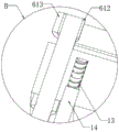
a second driving motor 611 is fixedly arranged on one side of the front face of the crushing box 1, a transmission shaft of the second driving motor 611 is fixedly connected with one end of one of the two-way screw rods 61, belt pulleys 612 are fixedly arranged on the surfaces of the two-way screw rods 61, a linkage belt 613 is connected between the two belt pulleys 612 in a transmission manner and is connected with the two belt pulleys 612 in a transmission manner through the linkage belt 613, so that one of the two-way screw rods 61 can drive the other two-way screw rod 61 to rotate at the same speed when rotating;
the inner walls of the two front sides of the two first sliding chutes 63 are fixedly provided with return springs 13, one ends of the four return springs 13 are fixedly provided with baffles 14, the four baffles 14 are respectively and fixedly connected with the four movable plates 2, and the four movable plates 2 can respectively drive the four baffles 14 to move while sliding, so that the inner part of the crushing box 1 is sealed;
a switch panel 15 is fixedly arranged at the top of the front face of the crushing box 1, a first driving motor switch, a second driving motor switch and a blower switch are respectively arranged on the surface of the switch panel 15, and the two first driving motors 16, the second driving motor 611 and the blower 20 are respectively and electrically connected with a power supply through the first driving motor switch, the second driving motor switch and the blower switch;
specifically, as shown in fig. 1, fig. 2, fig. 3, fig. 4 and fig. 5, the second driving motor switch on the surface of the switch panel 15 is first turned on, the second driving motor 611 is started to drive one of the two-way screws 61 to rotate, because the linkage belt 613 is in transmission connection with the two belt pulleys 612, the two-way screws 61 rotate at the same speed, the two-way screws 61 rotate to enable each two opposite movable plates 2 to respectively move relatively along the inner walls of the two first sliding grooves 63, the two movable plates 2 move to drive the two crushing shafts 3 to move relatively, and then the worker can conveniently adjust the distance between the two roller bodies 4 in the crusher, so that the crusher is suitable for feeds with different crushing degrees.
Example 2:
the flow control assembly 7 comprises an extension plate 71, an electric push rod 72, two second sliding grooves 73, a flow control plate 74 and a material through groove 75, the extension plate 71 is fixedly arranged at the top of one side of the crushing box 1, the electric push rod 72 is fixedly arranged at one side of the top end of the extension plate 71, the two second sliding grooves 73 are respectively formed in the inner walls of the tops of the two sides of the crushing box 1, the flow control plate 74 is connected between the two second sliding grooves 73 in a sliding manner, the flow control plate 74 is fixedly connected with the push rod of the electric push rod 72, and the material through groove 75 is formed in the inner wall of the middle part of the flow control plate 74;
a switch panel 15 is fixedly arranged at the top of the front surface of the crushing box 1, an electric push rod switch is arranged on the surface of the switch panel 15, and the electric push rod 72 is electrically connected with a power supply through the electric push rod switch;
specifically, as shown in fig. 1 and 3, the electric push rod switch on the surface of the switch panel 15 is first turned on, the push rod of the electric push rod 72 is extended to slide the flow control plate 74 between the two second chutes 73, and the flow control plate 74 gradually reduces the flow gap between the feed chute 75 and the feed hopper 9 during the sliding process, so as to adjust the feed discharge rate of the feed according to the working efficiency of the pulverizer.
The working principle is as follows: when specifically using, the utility model relates to a feed ingredient rubbing crusher, at first will open the electric putter switch on flush mounting plate 15 surface of switch, electric putter 72's push rod extension makes accuse and flows board 74 and slide between two second spouts 73, the gliding in-process of accuse board 74 makes the circulation gap between logical silo 75 and feeder hopper 9 reduce gradually, and then can be according to the unloading speed of this rubbing crusher's work efficiency adjustment fodder, then pour feed ingredient into the inside of feeder hopper 9, the in-process of fodder whereabouts falls into the top of two roll bodies 4 after two filter screens 12 filter, then open the first driving motor switch on flush mounting plate 15 surface of switch, two first driving motor 16 start-up drive two crushing roller 3 reverse rotations, two crushing roller 3 rotate and drive two rotation of crushing roller 4, a plurality of blade 5 smashes the fodder after filtering simultaneously, when fodder smashes the completion when the fodder is smashed, open the air-blower switch on flush mounting plate 15 surface of switch, air-blower 20 operation makes the dust, impurity filters the inside of going into feed bin 10 through the dust screen, the sealed lid that 18 inner wall of discharge opening in proper order and dust exhaust hole 17 inner wall 19 make this impurity pour this fodder respectively outside with the sealed lid.
Although embodiments of the present invention have been shown and described, it will be appreciated by those skilled in the art that various changes, modifications, substitutions and alterations can be made in these embodiments without departing from the principles and spirit of the invention, the scope of which is defined in the appended claims and their equivalents.
Claims (7)
1. The utility model provides a feed ingredient rubbing crusher, is including smashing case (1), its characterized in that, the equal sliding connection of inner wall of crushing case (1) both sides has two fly leaves (2), and per two is relative all rotate through the bearing between fly leaf (2) and be connected with crushing roller (3), two the equal fixed roll body (4) that are equipped with in surface of crushing roller (3), two the equal fixed blade (5) that are equipped with a plurality of equidistance setting in surface of roll body (4), with two of one side be equipped with adjusting part (6) between fly leaf (2), the top of smashing case (1) is equipped with accuse and flows subassembly (7), the top of smashing case (1) articulates there is apron (8), the fixed feeder hopper (9) that is equipped with in inner wall at apron (8) top middle part, two of one side of fly leaf (2) is all fixed be equipped with first same side driving motor (16), two the transmission shaft of first driving motor (16) respectively with the one end fixed connection of two crushing roller (3).
2. A feedstuff pulverizer as claimed in claim 1, wherein: adjusting part (6) include two-way lead screw (61), four screw-nut (62) and two first spout (63), two-way lead screw (61) all rotate respectively through the bearing and connect the inner wall in crushing case (1) front both sides, two the equal threaded connection in both sides of two-way lead screw (61) has screw-nut (62), four screw-nut (62) is fixed the inner wall that sets up in four fly leaf (2) respectively, two inner wall, two in crushing case (1) both sides bottom are seted up respectively in first spout (63) respectively with two with one side fly leaf (2) sliding connection.
3. A feedstuff pulverizer as claimed in claim 2, wherein: smash the fixed second driving motor (611) that is equipped with in one side of case (1) front, the transmission shaft of second driving motor (611) and the one end fixed connection of one of them two-way lead screw (61), two the surface of two-way lead screw (61) all is fixed and is equipped with belt pulley (612), two the transmission is connected with linkage belt (613) between belt pulley (612).
4. A feedstuff pulverizer as claimed in claim 3, wherein: the flow control assembly (7) comprises an extension plate (71), an electric push rod (72), two second sliding grooves (73), a flow control plate (74) and a material passing groove (75), the extension plate (71) is fixedly arranged at the top of one side of the crushing box (1), the electric push rod (72) is fixedly arranged at one side of the top end of the extension plate (71), the two second sliding grooves (73) are respectively arranged on the inner walls of the tops of the two sides of the crushing box (1), the flow control plate (74) is connected between the two second sliding grooves (73) in a sliding mode, the flow control plate (74) is fixedly connected with the push rod of the electric push rod (72), and the material passing groove (75) is formed in the inner wall of the middle of the flow control plate (74).
5. A feedstuff pulverizer as claimed in claim 4, wherein: the dust collecting device is characterized in that a dust collecting bin (10) is fixedly arranged in the middle of the other side of the crushing box (1), an air blower (20) is fixedly arranged on the inner wall of one side of the dust collecting bin (10), a material passing hole (11) is formed between the dust collecting bin (10) and the crushing box (1), a filter screen (12) is fixedly arranged on the inner wall of the material passing hole (11) and the inner part of the feed hopper (9), a dust screen is fixedly arranged at the end of the air blowing end of the air blower (20), a dust discharging hole (17) is formed in the bottom end of the inner wall of the dust collecting bin (10), a discharging hole (18) is formed in the bottom end of one side of the crushing box (1), and a sealing cover (19) is in threaded connection with the inner wall of the discharging hole (18) and the inner wall of the dust discharging hole (17).
6. A feedstuff pulverizer as claimed in claim 2, wherein: two the inner wall of the positive both sides of first spout (63) all fixedly is equipped with reset spring (13), four the one end of reset spring (13) all fixedly is equipped with baffle (14), four baffle (14) respectively with four fly leaf (2) fixed connection.
7. A feedstuff pulverizer as claimed in claim 5, wherein: smash the positive top of case (1) and fix and be equipped with flush mounting plate of switch (15), the surface of flush mounting plate of switch (15) is equipped with first driving motor switch, second driving motor switch, electric putter switch and air-blower switch respectively, two first driving motor (16), second driving motor (611), electric putter (72) and air-blower (20) are respectively through first driving motor switch, second driving motor switch, electric putter switch and air-blower switch and power electric connection.
Priority Applications (1)
| Application Number | Priority Date | Filing Date | Title |
|---|---|---|---|
| CN202222752996.4U CN218531212U (en) | 2022-10-19 | 2022-10-19 | Feed ingredient rubbing crusher |
Applications Claiming Priority (1)
| Application Number | Priority Date | Filing Date | Title |
|---|---|---|---|
| CN202222752996.4U CN218531212U (en) | 2022-10-19 | 2022-10-19 | Feed ingredient rubbing crusher |
Publications (1)
| Publication Number | Publication Date |
|---|---|
| CN218531212U true CN218531212U (en) | 2023-02-28 |
Family
ID=85279853
Family Applications (1)
| Application Number | Title | Priority Date | Filing Date |
|---|---|---|---|
| CN202222752996.4U Active CN218531212U (en) | 2022-10-19 | 2022-10-19 | Feed ingredient rubbing crusher |
Country Status (1)
| Country | Link |
|---|---|
| CN (1) | CN218531212U (en) |
Cited By (1)
| Publication number | Priority date | Publication date | Assignee | Title |
|---|---|---|---|---|
| CN117181783A (en) * | 2023-10-26 | 2023-12-08 | 甘肃省科学院生物研究所 | Gardens discarded object is smashed and is loosened material device with adjustable blade interval |
-
2022
- 2022-10-19 CN CN202222752996.4U patent/CN218531212U/en active Active
Cited By (1)
| Publication number | Priority date | Publication date | Assignee | Title |
|---|---|---|---|---|
| CN117181783A (en) * | 2023-10-26 | 2023-12-08 | 甘肃省科学院生物研究所 | Gardens discarded object is smashed and is loosened material device with adjustable blade interval |
Similar Documents
| Publication | Publication Date | Title |
|---|---|---|
| CN108097406A (en) | Vertical crushing plant | |
| CN105457715A (en) | Horizontal rotary drum grinder and grinding apparatus thereof | |
| CN211964514U (en) | Attapulgite powder grinding device | |
| CN218531212U (en) | Feed ingredient rubbing crusher | |
| CN212299673U (en) | Heavy calcium carbonate powder dispersion drying device | |
| CN115646586A (en) | Coal mining crushing system and crushing process | |
| CN209348741U (en) | A kind of hammer slice type multi-stage separation feed grinder | |
| CN215029496U (en) | Medicine pulverizer for animal husbandry | |
| CN214864025U (en) | Feed grinder | |
| CN212855919U (en) | Novel galactomannan smashes pelletization device | |
| CN112221596A (en) | Waste collecting device for machine-building | |
| CN216099898U (en) | High-efficient rubbing crusher of usefulness is handled to old and useless plastic bag | |
| CN214916727U (en) | Processing stevioside rubbing crusher | |
| CN218359463U (en) | Grain grinder | |
| CN220941112U (en) | Microparticle milling equipment | |
| CN219308917U (en) | Crushing and grinding device for solid chemical raw materials | |
| CN215541513U (en) | Blade type flour mill | |
| CN219356416U (en) | Raw material pretreatment equipment | |
| CN115254248B (en) | Grinding process capable of screening final powder in advance | |
| CN213611892U (en) | Mineral powder mill for mining | |
| CN219130311U (en) | Waste stirring and crushing device for lithium battery recovery | |
| CN214131824U (en) | Flour mill | |
| CN220835750U (en) | Grinder for pig feed processing | |
| CN220835985U (en) | Old metal quick crushing device | |
| CN214288710U (en) | Spinel type composite oxide MnCo2O4 crushing and grinding device |
Legal Events
| Date | Code | Title | Description |
|---|---|---|---|
| GR01 | Patent grant | ||
| GR01 | Patent grant |