CN218269823U - Rotary flash dryer - Google Patents
Rotary flash dryer Download PDFInfo
- Publication number
- CN218269823U CN218269823U CN202221658492.XU CN202221658492U CN218269823U CN 218269823 U CN218269823 U CN 218269823U CN 202221658492 U CN202221658492 U CN 202221658492U CN 218269823 U CN218269823 U CN 218269823U
- Authority
- CN
- China
- Prior art keywords
- drying cylinder
- air supply
- air
- drying
- thick bamboo
- Prior art date
- Legal status (The legal status is an assumption and is not a legal conclusion. Google has not performed a legal analysis and makes no representation as to the accuracy of the status listed.)
- Active
Links
Images


Landscapes
- Crushing And Pulverization Processes (AREA)
Abstract
The utility model discloses a rotary flash drying machine in drying equipment technical field, including a drying section of thick bamboo, the drying section of thick bamboo side is equipped with the surge drum, be connected through the discharging pipe between surge drum and the drying section of thick bamboo, the inside rubbing crusher that is equipped with of drying section of thick bamboo, the fixed inlet pipe that is equipped with of drying section of thick bamboo side, the matching is equipped with the screen cloth frame in the middle part of the drying section of thick bamboo, the screen cloth frame is located the inlet pipe upside, the inside fixed screen cloth that is equipped with of screen cloth frame, the drying section of thick bamboo is equipped with the slip chamber that matches with the screen cloth frame, and the screen cloth frame can be dismantled with the slip chamber and be connected, screen cloth frame upside matches and is equipped with the arc deflector, and arc deflector and drying section of thick bamboo fixed connection, the discharging pipe is located between screen cloth frame and the arc deflector, the fixed wind plate that is equipped with in drying section of thick bamboo bottom, wind plate downside matches and is equipped with air supply mechanism. The utility model discloses can prevent effectively that the material from not smashing the condition that just is taken out of the drying cylinder by the wind completely to can effectively smash the great material of jam, and can carry out even air supply, effectively improve drying efficiency.
Description
Technical Field
The utility model relates to a drying equipment technical field especially relates to spin flash dryer.
Background
In material production, can often use the desiccator, the desiccator is the drying equipment that reduces material moisture, and the drying equipment on the present market is various, and spin flash desiccator is just one of them, compares in traditional drying equipment, and spin flash desiccator is the novel continuous type drying equipment of collecting drying, smashing, screening in an organic whole, and the product quality that especially is applicable to filter cake form, paste form, the stoving of thin mud form material, and the product quality that its dried out is very big relation with dry temperature, wind speed, amount of wind, crushing speed.
Current spin flash dryer, in the use, the condition that the material has not yet been smashed completely just is carried out the drying cylinder by the wind, and has the inhomogeneous condition of blowing.
As in the Chinese patent: CN211177883U discloses a spin flash dryer, further specifically discloses: including base, cutting device and wind device, cutting device includes motor, flabellum and blade, and the wind device includes wind gap, fan and discharge gate, and the last fixed surface of base is connected with the drying cabinet, and the power chamber has been seted up to the inside of base, inner diapire fixedly connected with motor in power chamber, the output shaft fixedly connected with rotation axis of motor, the rotation axis extends to the inside of drying cabinet.
The utility model has the following disadvantages: the wind gap that its set up is located device lower extreme one side, only at one end air inlet, has the inhomogeneous condition of blowing, leads to material drying efficiency high inadequately, and the screen cloth of its setting, though can effectively filter, nevertheless lack and carry out shredding mechanism to filterable great material, cause the jam easily, and the screen cloth of its setting can't be carried out convenient tearing open and trade.
To this end, we propose a spin flash dryer to solve the above problems.
SUMMERY OF THE UTILITY MODEL
The utility model aims at solving the defects existing in the prior art and providing a spin flash dryer.
In order to achieve the above purpose, the utility model adopts the following technical scheme:
spin flash dryer, including the drying cylinder, the drying cylinder side is equipped with the surge drum, be connected through the discharging pipe between surge drum and the drying cylinder, the inside rubbing crusher that is equipped with of drying cylinder, the fixed inlet pipe that is equipped with in drying cylinder side, the matching of drying cylinder middle part is equipped with the screen cloth frame, the screen cloth frame is located the inlet pipe upside, the inside fixed screen cloth that is equipped with of screen cloth frame, the drying cylinder is equipped with the slip chamber that matches with the screen cloth frame, and the screen cloth frame can be dismantled with the slip chamber and be connected, the matching of screen cloth frame upside is equipped with the arc deflector, and arc deflector and drying cylinder fixed connection, the discharging pipe is located between screen cloth frame and the arc deflector, the fixed wind plate that is equipped with in drying cylinder bottom, the matching of wind plate downside is equipped with air supply mechanism.
Preferably, an air outlet is formed in the upper end of the collecting cylinder, a cloth bag corresponding to the air outlet is fixedly arranged at the upper end of the collecting cylinder, and a discharge port is vertically and fixedly formed in the lower end of the collecting cylinder.
Preferably, rubbing crusher constructs including the axis of rotation, the horizontal fixed bracing piece that is equipped with of screen frame downside, the axis of rotation upper end is rotated with the bracing piece and is connected, the axis of rotation lower extreme runs through wind dish and dry bobbin base portion, the fixed crushing motor that is equipped with in dry bobbin base portion, and crushing motor and the coaxial fixed connection of axis of rotation, the coaxial fixed crushing cutter that is equipped with in axis of rotation upper end, and go up the crushing cutter and be close to screen frame downside, the coaxial fixed crushing cutter that is equipped with down of axis of rotation lower extreme, and the crushing cutter is close to the wind dish upside down.
Preferably, the air plate is horizontally arranged, the diameter of the air plate is the same as the inner diameter of the drying cylinder, and a plurality of blowing pipes are uniformly arranged on the air plate.
Preferably, air supply mechanism includes the supply-air outlet, the supply-air outlet is the ring form, and the coaxial cover of supply-air outlet establishes in the axis of rotation, the supply-air outlet passes through connecting rod and dry section of thick bamboo lateral wall fixed connection, the fixed and intercommunication of supply-air outlet downside symmetry has two branch pipes, two the branch pipe other end all communicates with a blast pipe fixed connection, the blast pipe is the form of bending to run through dry section of thick bamboo, the fixed matching of blast pipe one end is equipped with the fan.
Preferably, the fixed feeder hopper that is equipped with of inlet pipe one end, the inside matching of inlet pipe is equipped with the spiral leaf, the fixed driving motor that is equipped with of inlet pipe one end, driving motor and the coaxial fixed connection of spiral leaf.
Compared with the prior art, the beneficial effects of the utility model are that:
the utility model discloses a discharging pipe position that sets up the drying cylinder sets up the screen frame, be provided with the filter screen in the screen frame, thereby realize filtering the material of not smashing completely, prevent effectively that the material from smashing completely and just being taken out the condition of drying cylinder by the wind, and the screen frame can carry out convenient dismantlement, convenient maintenance is changed, simultaneously through setting up rubbing crusher constructs, the realization is to the smashing of material, and rubbing crusher constructs and is provided with crushing cutter at the filter screen downside, can smash the great material that comes to blow on, prevent effectively that the filter screen from being stopped up by the material of collecting in a long-pending mode, simultaneously through setting up air supply mechanism, air supply mechanism is equipped with the annular supply-air outlet of circle, can realize effectual even air supply effect, effectively improve the drying efficiency of material.
Drawings
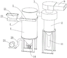
Fig. 1 is a schematic structural view of a spin flash dryer according to the present invention;
fig. 2 is a schematic view of the internal structure of a drying cylinder and a collecting cylinder in the spin flash dryer of the present invention;
fig. 3 is a schematic structural diagram of an air plate in the spin flash dryer provided by the present invention;
fig. 4 is a schematic structural diagram of a screen frame in the spin flash dryer provided by the present invention.
In the figure: the device comprises a drying cylinder 1, a collecting cylinder 2, a discharging pipe 3, a feeding pipe 4, a screen frame 5, a screen 6, an arc-shaped guide plate 7, an air disc 8, an air outlet 9, a cloth bag 10, a discharge port 11, a rotating shaft 12, a support rod 13, a crushing motor 14, an upper crushing cutter 15, a lower crushing cutter 16, a blowing pipe 17, an air supply outlet 18, branch pipes 19, an air supply pipe 20, a feed hopper 21, a spiral blade 22, a driving motor 23 and a fan 24.
Detailed Description
The technical solutions in the embodiments of the present invention will be described clearly and completely with reference to the accompanying drawings in the embodiments of the present invention, and it is obvious that the described embodiments are only some embodiments of the present invention, not all embodiments.
Referring to fig. 1-4, a spin flash dryer comprises a drying cylinder 1, a collecting cylinder 2 is arranged on the side of the drying cylinder 1, the drying cylinder 1 and the collecting cylinder 2 are both fixed with the existing ground through a support frame, the collecting cylinder 2 is connected with the drying cylinder 1 through a discharging pipe 3, an air outlet 9 is arranged at the upper end of the collecting cylinder 2, the air outlet 9 is used for discharging air, a cloth bag 10 corresponding to the air outlet 9 is fixedly arranged at the upper end of the collecting cylinder 2, the cloth bag 10 is used for filtering materials and preventing the materials from being discharged from the air outlet 9, a discharging port 11 is vertically and fixedly arranged at the lower end of the collecting cylinder 2, the discharging port 11 is used for discharging materials, the material can be discharged, a crushing mechanism is arranged in the drying cylinder 1, an air disk 8 is fixedly arranged at the bottom of the drying cylinder 1, the air disk 8 is horizontally arranged, the diameter of the air disk 8 is the same as the inner diameter of the drying cylinder 1, a plurality of blowing pipes 17 are uniformly arranged on the air disk 8, the plurality of blowing pipes 17 facilitate uniform air supply, the crushing mechanism comprises a rotating shaft 12, a support rod 13 is transversely and fixedly arranged at the lower side of the screen frame 5, the upper end of the rotating shaft 12 is rotatably connected with the support rod 13, the support rod 13 supports and limits the rotating shaft 12, the lower end of the rotating shaft 12 penetrates through the bottoms of the air disk 8 and the drying cylinder 1, bearings matched with the rotating shaft 12 are arranged at the bottoms of the air disk 8 and the drying cylinder 1, a crushing motor 14 is fixedly arranged at the bottom of the drying cylinder 1, and the crushing motor 14 is coaxially and fixedly connected with the rotating shaft 12, the crushing motor 14 is started to drive the rotating shaft 12 to rotate, the upper end of the rotating shaft 12 is coaxially and fixedly provided with an upper crushing cutter 15, the lower end of the rotating shaft 12 is coaxially and fixedly provided with a lower crushing cutter 16, the lower crushing cutters 16 are close to the upper side of the air disc 8, the lower crushing cutters 16 are provided with a plurality of groups, the lower crushing cutters 16 are used for crushing materials, and the rotating shaft 12 rotates to drive the upper crushing cutters 15 and the lower crushing cutters 16 to rotate;
the side edge of the drying cylinder 1 is fixedly provided with a feeding pipe 4, one end of the feeding pipe 4 is fixedly provided with a feeding hopper 21, the feeding hopper 21 is used for feeding materials, the inside of the feeding pipe 4 is provided with a spiral blade 22 in a matching way, one end of the feeding pipe 4 is fixedly provided with a driving motor 23, the driving motor 23 is coaxially and fixedly connected with the spiral blade 22, the driving motor 23 drives the spiral blade 22 to rotate, so as to realize the uniform-speed propulsion of the materials and further realize the uniform-speed feeding effect, the middle part of the drying cylinder 1 is provided with a screen frame 5 in a matching way, the screen frame 5 is positioned on the upper side of the feeding pipe 4, a screen 6 is fixedly arranged inside the screen frame 5, and the screen 6 is used for preventing the materials from being brought out of the drying cylinder 1 by wind without being completely crushed, the drying cylinder 1 is provided with a sliding cavity matched with the screen frame 5, the screen frame 5 is detachably connected with the sliding cavity, the screen frame 5 can be conveniently detached and conveniently maintained and replaced, the upper side of the screen frame 5 is provided with an arc-shaped guide plate 7 in a matched mode, the arc-shaped guide plate 7 is fixedly connected with the drying cylinder 1, the upper crushing cutter 15 is close to the lower side of the screen frame 5, the upper crushing cutter 15 can crush larger materials blown up, the filter screen 6 is effectively prevented from being blocked by the accumulated materials, the discharge pipe 3 is located between the screen frame 5 and the arc-shaped guide plate 7, and the arc-shaped guide plate 7 plays a role in effective guiding;
8 downside matchings of wind dish are equipped with air supply mechanism, air supply mechanism includes supply-air outlet 18, supply-air outlet 18 level sets up at 8 lower extremes of wind dish, supply-air outlet 18 is the ring form, and the coaxial cover of supply-air outlet 18 is established on axis of rotation 12, supply-air outlet 18 can carry out the even air supply, supply-air outlet 18 passes through connecting rod and 1 lateral wall fixed connection of drying cylinder, the symmetry is fixed and the intercommunication has two branch pipes 19 of supply-air outlet 18 downside, two branch pipes 19 play the effect of even transport, the 19 other ends of two branch pipes all with a supply-air duct 20 fixed connection and intercommunication, supply-air duct 20 is the form of bending, and run through drying cylinder 1, the fixed matching of supply-air duct 20 one end is equipped with fan 24, supply-air duct 20 can be equipped with the heating wire, make fan 24 carry out hot-blast transportation, supply-air duct 20 can deliver to supply-air outlet 18 departments with wind.
The utility model discloses in, the device's theory of operation as follows:
during drying processing, feeding materials into the feed hopper 21, driving the spiral blade 22 to rotate by the driving motor 23, enabling the spiral blade 22 to push the materials at a constant speed, and enabling the materials to enter the drying cylinder 1; the grinding motor 14 is started to drive the rotating shaft 12 to rotate, the rotating shaft 12 rotates to drive the upper grinding cutter 15 and the lower grinding cutter 16 to rotate, the lower grinding cutter 16 grinds materials, the fan 24 starts to supply air at the moment, the air supply pipe 20 supplies the air to the air supply opening 18, and uniform air supply is achieved through a plurality of injection pipes 17 on the air disc 8; the crushed lighter materials are dried and discharged into the collecting cylinder 2 through the screen 6, the cloth bag 10 prevents the materials from being discharged from the air outlet 9, and finally the materials are discharged from the discharge port 11; meanwhile, the upper crushing cutter 15 crushes the larger materials blown up, so that the filter screen 6 is effectively prevented from being blocked by the accumulated materials; when maintaining, screen frame 5 can carry out convenient dismantlement, convenient maintenance is changed.
The above, only be the embodiment of the preferred of the present invention, but the protection scope of the present invention is not limited thereto, and any person skilled in the art is in the technical scope of the present invention, according to the technical solution of the present invention and the utility model, which are designed to be replaced or changed equally, all should be covered within the protection scope of the present invention.
Claims (6)
1. Rotary flash evaporation desiccator, including drying cylinder (1), its characterized in that, drying cylinder (1) side is equipped with surge drum (2), be connected through discharging pipe (3) between surge drum (2) and drying cylinder (1), drying cylinder (1) inside rubbing crusher constructs that is equipped with, drying cylinder (1) side is fixed to be equipped with inlet pipe (4), drying cylinder (1) middle part matches and is equipped with screen frame (5), screen frame (5) are located inlet pipe (4) upside, screen frame (5) inside fixed screen cloth (6) that is equipped with, drying cylinder (1) are equipped with the sliding chamber that matches with screen frame (5), and screen frame (5) can dismantle with the sliding chamber and be connected, screen frame (5) upside matching is equipped with arc deflector (7), and arc deflector (7) and drying cylinder (1) fixed connection, discharging pipe (3) are located between screen frame (5) and arc deflector (7), drying cylinder (1) bottom is fixed to be equipped with wind dish (8), wind dish (8) downside matching is equipped with air supply mechanism.
2. A spin flash dryer according to claim 1, wherein an air outlet (9) is provided at the upper end of the collecting cylinder (2), a cloth bag (10) corresponding to the air outlet (9) is fixedly provided at the upper end of the collecting cylinder (2), and a discharge hole (11) is vertically and fixedly provided at the lower end of the collecting cylinder (2).
3. The spin flash dryer of claim 1, wherein the crushing mechanism comprises a rotating shaft (12), a support rod (13) is transversely and fixedly arranged on the lower side of the screen frame (5), the upper end of the rotating shaft (12) is rotatably connected with the support rod (13), the lower end of the rotating shaft (12) penetrates through the bottoms of the air disc (8) and the drying cylinder (1), a crushing motor (14) is fixedly arranged on the bottom of the drying cylinder (1), the crushing motor (14) is fixedly connected with the rotating shaft (12) in a coaxial manner, an upper crushing cutter (15) is fixedly arranged on the upper end of the rotating shaft (12), the upper crushing cutter (15) is close to the lower side of the screen frame (5), a lower crushing cutter (16) is fixedly arranged on the lower end of the rotating shaft (12) in a coaxial manner, and the lower crushing cutter (16) is close to the upper side of the air disc (8).
4. A spin flash dryer according to claim 1, characterized in that the air disk (8) is arranged horizontally, the diameter of the air disk (8) is the same as the inner diameter of the drying cylinder (1), and a plurality of blowing pipes (17) are uniformly arranged on the air disk (8).
5. The spin flash dryer according to claim 3, wherein the air supply mechanism comprises an air supply opening (18), the air supply opening (18) is annular, the air supply opening (18) is coaxially sleeved on the rotating shaft (12), the air supply opening (18) is fixedly connected with the side wall of the drying cylinder (1) through a connecting rod, two branch pipes (19) are symmetrically fixed on the lower side of the air supply opening (18) and communicated with the lower side of the air supply opening, the other ends of the branch pipes (19) are fixedly connected and communicated with an air supply pipe (20), the air supply pipe (20) is bent and penetrates through the drying cylinder (1), and a fan (24) is fixedly matched with one end of the air supply pipe (20).
6. A spin flash dryer according to claim 1, wherein a feed hopper (21) is fixed to one end of the feed pipe (4), a spiral blade (22) is arranged inside the feed pipe (4) in a matching manner, a driving motor (23) is fixed to one end of the feed pipe (4), and the driving motor (23) is coaxially and fixedly connected with the spiral blade (22).
Priority Applications (1)
| Application Number | Priority Date | Filing Date | Title |
|---|---|---|---|
| CN202221658492.XU CN218269823U (en) | 2022-06-29 | 2022-06-29 | Rotary flash dryer |
Applications Claiming Priority (1)
| Application Number | Priority Date | Filing Date | Title |
|---|---|---|---|
| CN202221658492.XU CN218269823U (en) | 2022-06-29 | 2022-06-29 | Rotary flash dryer |
Publications (1)
| Publication Number | Publication Date |
|---|---|
| CN218269823U true CN218269823U (en) | 2023-01-10 |
Family
ID=84758735
Family Applications (1)
| Application Number | Title | Priority Date | Filing Date |
|---|---|---|---|
| CN202221658492.XU Active CN218269823U (en) | 2022-06-29 | 2022-06-29 | Rotary flash dryer |
Country Status (1)
| Country | Link |
|---|---|
| CN (1) | CN218269823U (en) |
Cited By (1)
| Publication number | Priority date | Publication date | Assignee | Title |
|---|---|---|---|---|
| CN117367063A (en) * | 2023-12-07 | 2024-01-09 | 常州润凯干燥科技有限公司 | High-efficient rotary-type flash drying equipment |
-
2022
- 2022-06-29 CN CN202221658492.XU patent/CN218269823U/en active Active
Cited By (2)
| Publication number | Priority date | Publication date | Assignee | Title |
|---|---|---|---|---|
| CN117367063A (en) * | 2023-12-07 | 2024-01-09 | 常州润凯干燥科技有限公司 | High-efficient rotary-type flash drying equipment |
| CN117367063B (en) * | 2023-12-07 | 2024-03-12 | 常州润凯干燥科技有限公司 | High-efficient rotary-type flash drying equipment |
Similar Documents
| Publication | Publication Date | Title |
|---|---|---|
| CN209952937U (en) | Dry all-in-one of grinding is smashed to chinese-medicinal material | |
| CN107442235A (en) | A kind of material automatic fine pulverizer with drying function | |
| CN204742573U (en) | Feed disintegrator | |
| CN218269823U (en) | Rotary flash dryer | |
| CN112718154A (en) | Wheat bran reducing mechanism with stoving function | |
| CN109201272A (en) | A kind of feed processing disintegrating apparatus and its application method | |
| CN111589538A (en) | A multistage crushing apparatus for producing pig feed | |
| CN104209167A (en) | Pulverizer | |
| CN109417917A (en) | A kind of crusher for straw | |
| CN210675402U (en) | Fodder reducing mechanism | |
| CN208912293U (en) | A kind of feed processing raw material grinding device | |
| CN208449564U (en) | A kind of equipment that smashed rice is dried and dehydrated | |
| CN207076514U (en) | A kind of green fodder beating machine | |
| CN216058360U (en) | Straw rubbing crusher with sundry cleaning function | |
| CN213792103U (en) | Superfine pulverizer is used in architectural coatings production | |
| CN211668111U (en) | Crushing and drying device for production of high polymer materials | |
| CN210474177U (en) | Pulverizer for processing aquatic feed | |
| CN211436340U (en) | Crushing and mixing device for multiple dry plant tissues | |
| CN113477376A (en) | Food processing is with producing line waste material cleaning device | |
| CN208730069U (en) | Raw material suitable for cable reel production crushes drying integral machine | |
| CN219663859U (en) | Pulverizer with drying effect | |
| CN219836618U (en) | Drying device is smashed to lees fish fodder | |
| CN218048191U (en) | Industrial waste water treatment is with residue clearance reducing mechanism | |
| CN206560878U (en) | A kind of film waste pulverizer | |
| CN214371307U (en) | Feed drying device |
Legal Events
| Date | Code | Title | Description |
|---|---|---|---|
| GR01 | Patent grant | ||
| GR01 | Patent grant |