CN218269303U - Indoor unit of air conditioner - Google Patents
Indoor unit of air conditioner Download PDFInfo
- Publication number
- CN218269303U CN218269303U CN202221954694.9U CN202221954694U CN218269303U CN 218269303 U CN218269303 U CN 218269303U CN 202221954694 U CN202221954694 U CN 202221954694U CN 218269303 U CN218269303 U CN 218269303U
- Authority
- CN
- China
- Prior art keywords
- fan
- air
- flow guide
- inner cavity
- indoor unit
- Prior art date
- Legal status (The legal status is an assumption and is not a legal conclusion. Google has not performed a legal analysis and makes no representation as to the accuracy of the status listed.)
- Active
Links
Images


Landscapes
- Air-Conditioning Room Units, And Self-Contained Units In General (AREA)
Abstract
The utility model discloses an air-conditioning indoor unit, which comprises a shell, a fan, a heat exchanger and a flow guide piece, wherein a mounting inner cavity is formed in the shell, and an air inlet and an air outlet are formed on the shell; the fan is positioned in the mounting inner cavity and comprises a fan shell, fan blades dispersedly formed on the periphery of the fan shell and a wheel disc positioned at the input end of the fan shell; the heat exchanger is positioned in the mounting inner cavity and correspondingly mounted on the output side of the fan blades; the flow guide piece is connected in the installation inner cavity and positioned on the inner side of the air inlet, a connection inner cavity with an upward opening is formed in the flow guide piece, and the wheel disc part extends into the connection inner cavity; the flow guide piece is provided with a connecting inner cavity with an upward opening, and the wheel disc part extends into the connecting inner cavity; under the effect of connecting the inner chamber, the air current backward flow phenomenon that gets into between the heat exchanger disappears, reduces the inner loop, is favorable to reducing energy loss, improves the air output, and work efficiency is high, the noise reduction.
Description
Technical Field
The utility model belongs to the technical field of the air conditioner, specifically speaking relates to an indoor unit of air conditioner.
Background
Air conditioners are household appliances commonly used in daily life of people, and are classified into wall-mounted air conditioners and cabinet air conditioners. Among them, the air conditioner generally includes an indoor unit installed at an indoor side and an outdoor unit installed at an outdoor side.
In the indoor unit of the air conditioner, air is axially sucked in through a centrifugal fan blade, radially thrown out, subjected to heat exchange with a refrigerant in a heat exchanger and then blown into a room. Referring to fig. 9 and 10, in the conventional air conditioning indoor unit, because a large gap exists between the fan and the flow guide ring, air radially thrown out by the fan is not directly sucked into the air inlet of the fan again from the gap between the fan and the flow guide ring through the heat exchanger, which causes flow loss and noise generation.
Disclosure of Invention
An object of the utility model is to provide an indoor unit of air conditioner to solve the air current from fan output that exists among the prior art under the effect of heat exchanger resistance, there is the backward flow in the guide ring top, have some air current can inhale again through the clearance between fan and the guide ring, form the inner loop, cause flow loss and noise scheduling problem.
In order to realize the purpose of the utility model, the utility model adopts the following technical scheme to realize:
the utility model provides an indoor unit of air conditioner, it includes:
the air conditioner comprises a shell, a fan and a fan, wherein a mounting inner cavity is formed in the shell, and an air inlet and an air outlet are formed in the shell;
the fan is positioned in the installation inner cavity and comprises a fan shell, fan blades dispersedly formed on the periphery of the fan shell and a wheel disc positioned at the input end of the fan shell;
the heat exchanger is positioned in the installation inner cavity and correspondingly installed on the output side of the fan blades;
the flow guide piece is connected in the installation inner cavity and located on the inner side of the air inlet, a connection inner cavity with an upward opening is formed in the flow guide piece, and the wheel disc part extends into the connection inner cavity.
In some embodiments of the present application, the wheel disc is an annular structure, which gradually expands along a flowing direction of the airflow, the inner wall of the wheel disc is formed with a flow guiding surface for guiding the airflow to each of the fan blades, a horizontal connecting portion is formed above the wheel disc, and each of the fan blades is uniformly dispersed on the connecting portion.
In some embodiments of the present application, the flow guide member is an annular structure, a section of the flow guide member is an arc, and an installation gap H between an outer upper end surface of the flow guide member and the horizontal connecting portion is between 5 mm and 10mm.
In some embodiments of the present application, a gap H between the upper end surface of the outer side of the flow guide and the horizontal connecting portion is 6mm.
In some embodiments of the present application, the fan has a maximum outer diameter D ranging from 200mm to 450mm.
In some embodiments of the present application, a ratio of a radius R of a cross-sectional arc of the flow guide to a maximum outer diameter D of the fan is 0.06 to 0.10.
In some embodiments of the present application, the air conditioning indoor unit is characterized in that,
the ratio of the radius R of the section circular arc of the flow guide piece to the maximum outer diameter D of the fan is 0.08.
In some embodiments of the present application, a minimum distance L between the flow guide surface of the wheel disc and the connection cavity of the flow guide is 6 to 10mm.
In some embodiments of the present application, the water receiving tray is located below the heat exchanger, a water receiving tank with an upward opening is formed in the water receiving tray, and the water receiving tank is enclosed by a support portion and a first side wall and a second side wall which are vertically formed on the support portion; the heat exchanger bottom is located in the water receiving tank, first lateral wall includes inside wall and lateral wall, the top of lateral wall is formed with to the rectification inclined plane of inside wall direction slope.
In some embodiments of the present application, the fan is a centrifugal fan, two air outlets are formed in the housing, an air deflector is formed in each air outlet, the heat exchanger is a U-shaped heat exchanger, and an air flow is input from an input end of the fan, passes through the fan blades and the heat exchanger, and is output from the two air outlets respectively.
Compared with the prior art, the utility model discloses an advantage is with positive effect:
the utility model relates to a water conservancy diversion spare is formed with the connection inner chamber that the opening is up, the rim plate part extends to in the connection inner chamber.
The tangent plane of water conservancy diversion spare is opening arc structure up, and its one end that is located the rim plate dorsal part also is formed with the fender structure that separates that upwards extends, and under this effect that separates the fender structure, the air current backward flow phenomenon that gets into between the heat exchanger disappears, reduces the inner loop, is favorable to reducing energy loss, improves the air output, and work efficiency is high, in addition, the noise reduction, and user experience is better.
Other features and advantages of the present invention will become more apparent from the following detailed description of the invention when read in conjunction with the accompanying drawings.
Drawings
In order to more clearly illustrate the technical solutions in the embodiments of the present invention, the drawings needed to be used in the embodiments will be briefly described below, and it is obvious that the drawings in the following description are some embodiments of the present invention, and it is obvious for those skilled in the art to obtain other drawings without creative efforts.
Fig. 1 is a schematic view of a cutaway structure of an embodiment of an indoor unit of an air conditioner provided by the present invention;
FIG. 2 is a schematic view of the positions of the housing, the water pan and the diversion member;
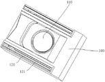
FIG. 3 is a schematic view of the external structure of the indoor unit of the air conditioner;
fig. 4 is a sectional plan view of an embodiment of an indoor unit of an air conditioner according to the present invention;
FIG. 5 is a schematic view showing the specific size and position of the flow guide member;
FIG. 6 is a schematic diagram of a heat exchanger configuration;
fig. 7 is a schematic plan view of an indoor unit of an air conditioner;
FIG. 8 is a schematic diagram of the specific size and position of the water pan;
FIG. 9 is a schematic view of a water pan and a flow guide member in the prior art;
FIG. 10 is a schematic view showing a state of air flow in the related art;
in the figure, the position of the first and second end faces,
100. a housing;
110. an air inlet;
120. an air outlet;
121. an air deflector;
130. an air outlet channel;
200. a fan;
210. a fan housing;
220. a fan blade;
230. a wheel disc;
300. a flow guide member;
301. a fixing plate;
310. the connecting inner cavity;
400. a heat exchanger;
500. a water pan;
501. a water receiving tank;
510. a support portion;
520. a first side wall;
521. a rectification slope;
530. a second side wall.
Detailed Description
The technical solutions in the embodiments of the present application will be clearly and completely described below with reference to the drawings in the embodiments of the present application, and it is obvious that the described embodiments are only a part of the embodiments of the present application, and not all of the embodiments. All other embodiments, which can be derived by a person skilled in the art from the embodiments given herein without making any creative effort, shall fall within the protection scope of the present application.
In the description of the present application, it is to be understood that the terms "center", "upper", "lower", "front", "rear", "left", "right", "vertical", "horizontal", "top", "bottom", "inner", "outer", and the like indicate orientations or positional relationships based on those shown in the drawings, merely for convenience of description and simplicity of description, and do not indicate or imply that the devices or elements referred to must have a particular orientation, be constructed in a particular orientation, and be operated, and thus, are not to be construed as limiting the present application.
The terms "first", "second" and "first" are used for descriptive purposes only and are not to be construed as indicating or implying relative importance or implicitly indicating the number of technical features indicated. Thus, a feature defined as "first" or "second" may explicitly or implicitly include one or more of that feature. In the description of the present application, the meaning of "a plurality" is two or more unless otherwise specified.
In the description of the present application, it should be noted that, unless otherwise explicitly stated or limited, the terms "mounted," "connected," and "connected" are to be construed broadly, and may be, for example, a fixed connection, a detachable connection, or an integral connection; may be mechanically coupled, may be directly coupled, or may be indirectly coupled through an intermediary. The specific meaning of the above terms in the present application can be understood in a specific case by those of ordinary skill in the art.
In the present disclosure, unless expressly stated or limited otherwise, the first feature "on" or "under" the second feature may comprise direct contact between the first and second features, or may comprise contact between the first and second features not directly. Also, the first feature being "on," "above" and "over" the second feature includes the first feature being directly on and obliquely above the second feature, or merely indicating that the first feature is at a higher level than the second feature. A first feature being "under," "below," and "beneath" a second feature includes the first feature being directly under and obliquely below the second feature, or simply meaning that the first feature is at a lesser elevation than the second feature.
The following disclosure provides many different embodiments or examples for implementing different features of the invention. In order to simplify the disclosure of the present invention, the components and arrangements of specific examples are described below. Of course, they are merely examples and are not intended to limit the present invention. Furthermore, the present invention may repeat reference numerals and/or reference letters in the various examples, which have been repeated for purposes of simplicity and clarity and do not in themselves dictate a relationship between the various embodiments and/or arrangements discussed.
The air conditioner performs a refrigeration cycle of the air conditioner by using a compressor, a condenser, an expansion valve, and an evaporator. The refrigeration cycle includes a series of processes involving compression, condensation, expansion, and evaporation to cool or heat an indoor space.
The low-temperature and low-pressure refrigerant enters the compressor, the compressor compresses the refrigerant gas in a high-temperature and high-pressure state, and the compressed refrigerant gas is discharged. The discharged refrigerant gas flows into the condenser. The condenser condenses the compressed refrigerant into a liquid phase, and heat is released to the surrounding environment through the condensation process.
The expansion valve expands the high-temperature and high-pressure liquid-phase refrigerant condensed in the condenser into a low-pressure liquid-phase refrigerant. The evaporator evaporates the refrigerant expanded in the expansion valve and returns the refrigerant gas in a low-temperature and low-pressure state to the compressor. The evaporator can achieve a cooling effect by heat-exchanging with a material to be cooled using latent heat of evaporation of a refrigerant. The air conditioner can adjust the temperature of the indoor space throughout the cycle.
The outdoor unit of the air conditioner refers to a portion of a refrigeration cycle including a compressor and an outdoor heat exchanger, the indoor unit of the air conditioner includes an indoor heat exchanger, and an expansion valve may be provided in the indoor unit or the outdoor unit.
The indoor heat exchanger and the outdoor heat exchanger serve as a condenser or an evaporator. When the indoor heat exchanger is used as a condenser, the air conditioner is used as a heater in a heating mode, and when the indoor heat exchanger is used as an evaporator, the air conditioner is used as a cooler in a cooling mode.
As shown in fig. 1 to 8, the present application provides an air conditioning indoor unit, which includes a casing 100 of the air conditioning indoor unit, a fan 200 installed in the casing 100, a heat exchanger 400, a water pan 500, and a deflector 300.
Referring to fig. 3, a mounting cavity is formed in the housing 100, and the fan 200, the heat exchanger 400, the water pan 500 and the baffle 300 are located in the mounting cavity, and an air inlet 110 and an air outlet 120 are formed in the housing 100.
Indoor airflow is input into the housing 100 from the air inlet 110, guided by the fan 200 and then conveyed to the heat exchanger 400, and after heat exchange is performed by the heat exchanger 400, air with a proper temperature is output from the air outlet 120.
An air deflector 121 for controlling the air outlet direction is arranged in the air outlet 120, and the air deflector 121 is rotatably installed in the air outlet.
Specifically, the fan 200 is a centrifugal fan 200, and includes a fan housing 210, fan blades 220 dispersedly formed on the outer periphery of the fan housing 210, and a wheel disc 230 located on the fan housing 210, wherein a gap is formed between adjacent fan blades 220 for airflow to pass through.
The fan 200 is externally connected with a driving motor, and under the driving of the driving motor, the fan 200 operates, and airflow is axially sucked by the fan 200, then works through a pressure surface of the fan blade 220, and is radially accelerated and radially thrown out.
The fan housing 210 has an input end, the wheel disc 230 is fixed to the input end of the fan housing 210, and the airflow is input from the air inlet 110 of the outer casing 100, passes through the gap between the fan blades 220, and is delivered to the heat exchanger 400.
In some embodiments of the present disclosure, in order to improve the air supply effect, two air outlets 120 are correspondingly formed on the housing 100.
Referring to fig. 6, the heat exchanger 400 is correspondingly installed at the output side of the fan blade 220, in order to improve the heat exchange effect and improve the operation stability, the heat exchanger 400 is designed as a U-shaped heat exchanger 400, two heat exchange end surfaces of the U-shaped heat exchanger 400 are respectively located at the inner sides of the two air outlets 120, and the air after heat exchange by the heat exchanger 400 is directly output from the corresponding air outlets 120.
Referring to fig. 1, 2 and 4, the air guide 300 is located between the intake vent 110 and the wheel disc 230 of the fan 200, is located inside the intake vent 110, and has an annular structure as a whole, a connection cavity 310 with an upward opening is formed in the air guide 300, and a portion below the wheel disc 230 extends into the connection cavity 310.
The end of the conventional flow guide 300 located at the inner side of the wheel disc 230 is bent upward, but the end located at the back side of the wheel disc 230 is of a horizontal structure, the airflow moves with acceleration through the fan 200, and after being axially sucked by the fan 200, the airflow is axially acted through the pressure surface of the fan 200 and radially thrown out with acceleration, and because the heat exchanger 400 has a certain resistance, a part of the airflow is sucked into the fan 200 again through the gap between the wheel disc 230 and the flow guide 300 to form internal circulation, which causes flow loss.
To avoid this problem, the baffle 300 according to the present application is formed with a connecting cavity 310 opened upward, and the disk 230 is partially extended into the connecting cavity 310.
Specifically, the section of the flow guiding element 300 is an arc structure with an upward opening, and an upward extending blocking structure is also formed at one end of the flow guiding element located at the back side of the wheel disc 230.
The wheel 230 is gradually expanded along the flowing direction of the airflow, a flow guide surface for guiding the airflow to the fan blades 220 is formed on the inner wall of the wheel 230, a horizontal connecting part is formed above the wheel 230, and the fan blades 220 are uniformly dispersed on the horizontal connecting part
Referring to fig. 5, in the indoor unit assembling structure, in order to avoid collision between the wheel disc 230 on the fan 200 and the air guide 300 during high-speed operation, an installation gap H between the upper end surface of the outer side of the air guide 300 and the horizontal connecting portion is between 5 mm and 10mm, and the distance is too large, so that airflow is easily transmitted back to the inner side of the fan 200 from the installation gap, flow loss is formed, and the gap is too small, and the airflow easily collides with the air guide 300 during the movement of the fan 200.
Therefore, it is preferable that the gap H between the outer upper end surface of the baffle 300 and the horizontal connection portion is 6mm.
Generally, the maximum outer diameter D of the fan 200 is 200mm to 450mm in consideration of the actual installation and the size of the indoor unit of the air conditioner.
In order to reduce the flow loss as much as possible on the basis of meeting the installation and operation conditions, researches prove that when the ratio of the radius R of the section arc of the flow guide piece 300 to the maximum outer diameter D of the fan 200 is within the range of 0.06 to 0.10, the airflow output is obviously improved, and preferably, the ratio of the radius R of the section arc of the flow guide piece 300 to the maximum outer diameter D of the fan 200 is selected to be 0.08.
Similarly, in order to meet installation and operation conditions, it is required to ensure that the minimum distance L between the flow guide surface of the wheel disc 230 and the connecting cavity 310 of the flow guide 300 is 6 to 10mm, the minimum distance is too small, so that collision is easy to occur in the operation process, the distance is too large, and vortex is easy to generate, and preferably, the minimum distance L between the flow guide surface of the wheel disc 230 and the connecting cavity 310 of the flow guide 300 is selected to be 7mm.
Referring to fig. 1, 2, 7, and 8, in some embodiments of the present application, since the heat exchanger 400 forms condensed water due to temperature difference during operation, in order to prevent the condensed water from condensing inside the casing 100 of the indoor unit of an air conditioner and even dripping indoors, which affects user experience, a water pan 500 for collecting the condensed water is disposed below the heat exchanger 400.
The water pan 500 is fixed in the housing 100, and the water pan 500 is connected to the flow guide 300 through the fixing plate.
A water receiving tank 501 with an upward opening direction is formed in the water receiving tray 500, the lower portion of the heat exchanger 400 is installed in the water receiving tank 501, and the size of the water receiving tank 501 is larger than that of the heat exchanger 400, so that all condensed water dropping from the heat exchanger 400 can be collected.
Specifically, the water receiving tank 501 is surrounded by a support portion 510 and a first sidewall 520 and a second sidewall 530 vertically formed on the support portion 510.
Since the heat exchanger 400 is in the form of a U-shaped heat exchanger 400 and is vertically disposed, most of the air flows through the gaps between the fins of the heat exchanger 400 at a certain angle and wind speed, and then flows through the air outlet 120.
The first sidewall 520 is located outside the water pan 500, and includes an inner sidewall and an outer sidewall, an air outlet channel 130 is formed between the outer sidewall and the sidewall of the installation cavity, and the air outlet channel 130 is communicated with the air outlet 120.
The airflow is output from the air outlet 120 through the air outlet channel 130, flows into the air outlet channel 130, and forms an airflow separation phenomenon under the action of the first sidewall 520, thereby generating a vortex and causing flow loss.
In order to reduce the phenomenon of air flow separation, a rectification slope 521 inclined toward the inner side wall is formed above the outer side wall.
Along the flowing direction of the air flow, the rectification slope 521 extends along the direction far away from the inner side wall, so as to guide the air flow into the air outlet channel 130, which is beneficial to avoiding the phenomenon of air flow separation.
The wall thickness of the first sidewall 520 is defined as a, the width of the air outlet channel 130 is defined as c, and experiments prove that the air outlet volume is obviously improved when the ratio of the wall thickness a of the first sidewall 520 to the width c of the air outlet channel 130 is within the range of 0.19 to 0.27.
Within the range of 0.19 to 0.27, the flow rate is increased and then decreased along with the increase of the ratio, and preferably, the ratio of the wall thickness a of the first side wall 520 to the width c of the air outlet channel 130 is 0.25.
In the indoor unit assembling structure, in order to ensure sufficient water capacity, strength and heat preservation of the water pan 500, the wall thickness a of the first side wall 520 needs to be ensured to be at least 10mm, and the thickness h of the supporting part 510 needs to be not less than 20mm.
The inclination angle b of the rectification inclined plane 521 is 40-60 degrees, and in the angle range, along with the increase of the ratio, the corresponding air outlet flow rate is increased firstly and then reduced.
Preferably, the angle b of inclination of the rectification slope 521 is 55 degrees.
The ratio of the wall thickness a of the first side wall 520 to the width c of the air outlet channel 130 is selected to be 0.25, the range of the inclination angle of the variable rectification inclined plane 521 is selected to be 48-54 degrees, 2 degrees is used as jumping for simulation, and the air outlet lifting percentages are respectively: 1.02%, 1.18%, 1.19%, 1.11%.
That is, when the inclination angle of the rectification slope 521 is 52 degrees, the air volume is increased by about 1.2%, and a considerable improvement effect is achieved.
In addition, after the rectification inclined plane 521 is added, the vortex area in the air outlet channel 130 is obviously reduced, and the air flow organization is smooth, which is also the reason for increasing the air volume.
In the foregoing description of embodiments, the particular features, structures, materials, or characteristics may be combined in any suitable manner in any one or more embodiments or examples.
The above embodiments of the present invention are only examples, but the scope of the present invention is not limited thereto, and any changes or substitutions that can be easily conceived by those skilled in the art within the technical scope of the present invention are also intended to be covered by the scope of the present invention.
Claims (10)
1. An indoor unit of an air conditioner, comprising:
the air conditioner comprises a shell, a fan and a fan, wherein a mounting inner cavity is formed in the shell, and an air inlet and an air outlet are formed in the shell;
the fan is positioned in the installation inner cavity and comprises a fan shell, fan blades dispersedly formed on the periphery of the fan shell and a wheel disc positioned at the input end of the fan shell;
the heat exchanger is positioned in the installation inner cavity and correspondingly installed on the output side of the fan blades;
the flow guide piece is connected in the installation inner cavity and located on the inner side of the air inlet, a connection inner cavity with an upward opening is formed in the flow guide piece, and the wheel disc part extends into the connection inner cavity.
2. An indoor unit of an air conditioner according to claim 1,
the wheel disc is of an annular structure and gradually expands along the flowing direction of the air flow, a flow guide surface used for guiding the air flow to the fan blades is formed on the inner wall of the wheel disc, a horizontal connecting part is formed above the wheel disc, and the fan blades are uniformly dispersed on the connecting part.
3. An indoor unit of an air conditioner according to claim 2,
the flow guide piece is of an annular structure, the section of the flow guide piece is arc-shaped, and the mounting gap H between the upper end face of the outer side of the flow guide piece and the horizontal connecting part is 5-10mm.
4. An indoor unit of an air conditioner according to claim 3,
the clearance H between the upper end surface of the outer side of the flow guide piece and the horizontal connecting part is 6mm.
5. An indoor unit of an air conditioner according to claim 1,
the size of the maximum outer diameter D of the fan is 200mm to 450mm.
6. An indoor unit of an air conditioner according to claim 5,
the ratio of the radius R of the section arc of the flow guide piece to the maximum outer diameter D of the fan is 0.06-0.10.
7. An indoor unit of an air conditioner according to claim 6,
the ratio of the radius R of the section circular arc of the flow guide piece to the maximum outer diameter D of the fan is 0.08.
8. An indoor unit of an air conditioner according to claim 1,
the minimum distance L between the flow guide surface of the wheel disc and the connecting inner cavity of the flow guide piece is 6-10mm.
9. An indoor unit of an air conditioner according to claim 1,
the water receiving tray is positioned below the heat exchanger, a water receiving groove with an upward opening direction is formed in the water receiving tray, and the water receiving groove is surrounded by a supporting part and a first side wall and a second side wall which are vertically formed on the supporting part; the heat exchanger bottom is located in the water receiving tank, first lateral wall includes inside wall and lateral wall, the top of lateral wall is formed with to the rectification inclined plane of inside wall direction slope.
10. An indoor unit of an air conditioner according to claim 1,
the fan is a centrifugal fan, two air outlets are formed in the shell, air deflectors are formed in each air outlet, the heat exchanger is a U-shaped heat exchanger, air flow is input from the input end of the fan, and is output from the two air outlets after passing through the fan blades and the heat exchanger.
Priority Applications (1)
| Application Number | Priority Date | Filing Date | Title |
|---|---|---|---|
| CN202221954694.9U CN218269303U (en) | 2022-07-27 | 2022-07-27 | Indoor unit of air conditioner |
Applications Claiming Priority (1)
| Application Number | Priority Date | Filing Date | Title |
|---|---|---|---|
| CN202221954694.9U CN218269303U (en) | 2022-07-27 | 2022-07-27 | Indoor unit of air conditioner |
Publications (1)
| Publication Number | Publication Date |
|---|---|
| CN218269303U true CN218269303U (en) | 2023-01-10 |
Family
ID=84763028
Family Applications (1)
| Application Number | Title | Priority Date | Filing Date |
|---|---|---|---|
| CN202221954694.9U Active CN218269303U (en) | 2022-07-27 | 2022-07-27 | Indoor unit of air conditioner |
Country Status (1)
| Country | Link |
|---|---|
| CN (1) | CN218269303U (en) |
-
2022
- 2022-07-27 CN CN202221954694.9U patent/CN218269303U/en active Active
Similar Documents
| Publication | Publication Date | Title |
|---|---|---|
| CN213362678U (en) | Indoor unit of air conditioner | |
| CN218269303U (en) | Indoor unit of air conditioner | |
| CN218328395U (en) | Indoor unit of air conditioner | |
| CN216346604U (en) | Indoor unit of air conditioner | |
| CN206160309U (en) | Kitchen air conditioner | |
| CN217540916U (en) | Outdoor unit of multi-connected unit | |
| CN220541221U (en) | Air duct machine | |
| CN219367782U (en) | Cabinet air conditioner indoor unit and cabinet air conditioner | |
| CN216814367U (en) | Indoor unit of air conditioner | |
| CN212657795U (en) | Vertical cabinet type air conditioner | |
| CN220065844U (en) | Air conditioner | |
| CN220065786U (en) | Air conditioner | |
| CN212618813U (en) | Air conditioner | |
| CN219350380U (en) | Air conditioner | |
| CN220021312U (en) | Air conditioner | |
| CN215570831U (en) | Indoor air conditioner | |
| CN212390507U (en) | Air conditioner | |
| CN220209067U (en) | Air conditioner | |
| CN215765968U (en) | A kind of refrigerator | |
| CN215523541U (en) | Indoor unit of air conditioner | |
| CN218154476U (en) | Indoor unit of air conditioner | |
| CN215597447U (en) | Indoor air conditioner | |
| CN100541025C (en) | Window air conditioner | |
| CN216897555U (en) | Air duct machine | |
| CN211876192U (en) | Outdoor unit of air conditioner |
Legal Events
| Date | Code | Title | Description |
|---|---|---|---|
| GR01 | Patent grant | ||
| GR01 | Patent grant |