CN213362678U - Indoor unit of air conditioner - Google Patents
Indoor unit of air conditioner Download PDFInfo
- Publication number
- CN213362678U CN213362678U CN202022270244.5U CN202022270244U CN213362678U CN 213362678 U CN213362678 U CN 213362678U CN 202022270244 U CN202022270244 U CN 202022270244U CN 213362678 U CN213362678 U CN 213362678U
- Authority
- CN
- China
- Prior art keywords
- heat exchanger
- peripheral side
- side plate
- air
- indoor unit
- Prior art date
- Legal status (The legal status is an assumption and is not a legal conclusion. Google has not performed a legal analysis and makes no representation as to the accuracy of the status listed.)
- Active
Links
Images


Landscapes
- Air Filters, Heat-Exchange Apparatuses, And Housings Of Air-Conditioning Units (AREA)
Abstract
The utility model discloses an air conditioner indoor unit, a shell comprises a bottom panel and a peripheral side panel, and a plurality of air outlets are arranged on the bottom panel; the heat exchanger is arranged in the shell and extends along the circumferential direction of the shell, two end parts of the heat exchanger are connected through a connecting plate, and a first air flow channel is formed between the heat exchanger and the circumferential side plate; the fan is arranged in the space enclosed by the heat exchanger and forms a second airflow channel with the heat exchanger; the water pump is arranged in the first air flow channel; the flow blocking part is arranged in the first air flow channel, and a gap is formed between the flow blocking part and the heat exchanger; the connecting plate includes plane portion and water conservancy diversion portion, and the two corresponds with the tip of heat exchanger respectively and is connected, and along the air current direction, the fender stream bit is in the upper reaches of water pump, and the water conservancy diversion portion inclines towards the direction that is close to the fan gradually and is located the upper reaches of plane portion. This application realizes the air-out homogeneity through the structural improvement of the setting of fender class portion and connecting plate.
Description
Technical Field
The utility model relates to an air conditioner technical field especially relates to an air-out runner of air conditioner indoor unit improves structure.
Background
The air supply uniformity of the indoor unit of the air conditioner is always concerned by consumers, so that manufacturers of air conditioning equipment continuously propose technical improvement schemes for the air conditioner, and commercial four-direction/two-direction/one-direction/Console all use a backward centrifugal fan as an air supply fan, and have the advantages that the backward centrifugal fan can easily obtain larger air volume and lower noise under the conditions of lower rotating speed and no volute.
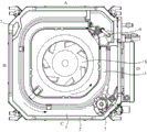
Taking a commercial indoor unit of an air conditioner with four-directional air outlet as an example, referring to fig. 1, the indoor unit comprises a casing, the casing is of an approximately square casing structure, the casing comprises a bottom panel 1 and four peripheral side panels 2 arranged on the bottom panel 1, and four air outlets, namely an air outlet a, an air outlet B, an air outlet C and an air outlet D, are symmetrically arranged around the bottom panel 1. Be equipped with heat exchanger 3 in the casing, heat exchanger 3 is around setting up along the circumferential direction of casing, and two tip of heat exchanger 3 pass through connecting plate 4 fixed connection. The fan 6 is arranged inside the heat exchanger 3, and airflow blown out from the fan 6 flows out from the air outlet after heat exchange of the heat exchanger 3, so that air conditioner adjustment is realized. As can be seen from fig. 1, the connection position of the two ends of the heat exchanger 3 is between the air outlet a and the air outlet D. A fresh air opening 7 and a water pump 5 are arranged in the shell, the fresh air opening 7 is located between the air outlet A and the air outlet B, and the water pump 5 is located between the air outlet C and the air outlet D. The water pump 5 is used for discharging condensed water generated by the heat exchanger 3 during operation in time, and is beneficial to improving heat exchange efficiency. Because fan 6 is circular motion and heat exchanger 3 is not regular shape around fan 6, the uneven problem of flow appears that so can't avoid, and this problem has been aggravated more to the separation of inside water pump 5, fresh air inlet 7 and heat exchanger connecting plate 4 to influence the air-out homogeneity of air outlet, influence the user and use experience.
Experiments show that the air outlet A is influenced by the fresh air inlet 7 and the heat exchanger connecting plate 4, and the air quantity of the air outlet A is slightly smaller than the air outlet B and the air outlet C. The internal flow channels of the air outlet B and the air outlet C are relatively wide, and the air quantity is almost equivalent. Air outlet D receives the shunt tubes of water pump 5, heat exchanger 3 and the influence of heat exchanger connecting plate 4, and the amount of wind is minimum in four air outlets, and the user can obviously perceive and be different from other air outlets. When the rotating speed of the fan is 800rpm, the difference between the air quantity of the air outlet B and the air outlet C is within 3 cubic meters per hour. The air quantity of the air outlet A, which is 10 cubic meters per hour different from that of the air outlet B and the air outlet C, accounts for 5%, and the air quantity of the air outlet D, which is 50 cubic meters per hour different from that of the air outlet B and the air outlet C, accounts for 26%. The uneven second problem of air outlet is air outlet condensation, because do not have enough amount of wind to blow away the moist hot-air on every side, lead to cold and hot air current to intersect, structural component condensation around the air outlet.
The above information disclosed in this background section is only for enhancement of understanding of the background of the application and therefore it may comprise prior art that does not constitute known to a person of ordinary skill in the art.
Disclosure of Invention
To the problem pointed out in the background art, the utility model provides an air conditioner, through the structural improvement of the setting of fender class portion and connecting plate, realize the air-out homogeneity.
In order to realize the purpose of the utility model, the utility model adopts the following technical scheme to realize:
in some embodiments of the present application, an indoor unit of an air conditioner is provided, including:
the shell comprises a bottom panel and a peripheral side plate arranged on the bottom panel, wherein a plurality of air outlets are formed in the bottom panel;
the heat exchanger is arranged in the shell and extends along the circumferential direction of the shell, two end parts of the heat exchanger are connected through a connecting plate, and a first air flow channel is formed between the heat exchanger and the circumferential side plate;
the fan is arranged in a space surrounded by the heat exchanger, and a second airflow channel is formed between the fan and the heat exchanger;
the water pump is arranged in the shell and positioned in the first air flow channel;
the flow blocking part is arranged in the shell and positioned in the first air flow channel, a gap for air flow to pass through is formed between the flow blocking part and the heat exchanger, and the flow blocking part is positioned at the upstream of the water pump along the air flow direction in the first air flow channel;
the connecting plate include plane portion and with the water conservancy diversion portion that plane portion connects, plane portion with the one end of heat exchanger is connected, water conservancy diversion portion with the other end of heat exchanger is connected, follows air current direction in the second airflow channel, water conservancy diversion portion is towards being close to gradually the direction slope of fan, just water conservancy diversion portion is located the upper reaches of plane portion.
In some embodiments of this application, week curb plate is including the first week curb plate, second week curb plate, third week curb plate and the fourth curb plate that connect gradually, be equipped with first air outlet, second air outlet, third air outlet and fourth air outlet on the bottom surface board correspondingly, the connecting plate is located first air outlet with between the fourth air outlet, the water pump is located the third air outlet with between the fourth air outlet, the fender class portion is located third air outlet side.
In some embodiments of this application, water conservancy diversion portion includes rake and transition portion, the transition portion is located plane portion with between the rake, the transition portion respectively with plane portion the circular arc transition between the rake, the one end of rake with the heat exchanger is connected, follows air flow direction in the second airflow channel, the rake is towards being close to gradually the direction slope of fan.
In some embodiments of this application, be equipped with first connecting portion on the first week curb plate, be equipped with the second connecting portion on the curb plate all around the fourth, the one end of heat exchanger with first connecting portion are connected, the other end of heat exchanger with the second connecting portion are connected, first connecting portion the second connecting portion the connecting plate first week curb plate and curb plate all around enclose into first space, follow the pipeline warp that the heat exchanger was drawn forth first space is drawn forth.
In some embodiments of the present application, a reinforcing bead is provided on the planar portion.
In some embodiments of the present application, the planar portion with the rake is close to be equipped with first kink on one side of heat exchanger respectively, first kink with the end connection of heat exchanger, the planar portion with the rake is close to be equipped with the second kink on one side of bottom panel respectively, the second kink with the bottom panel is connected.
In some embodiments of the present application, the flow blocking portion is disposed on the third peripheral side plate, and one side of the flow blocking portion, which is close to the heat exchanger, is an arc structure.
In some embodiments of the present application, the flow blocking portion is disposed near the water pump.
In some embodiments of the present application, a sloping plate is respectively disposed between the first peripheral side plate and the second peripheral side plate, between the second peripheral side plate and the third peripheral side plate, between the third peripheral side plate and the fourth peripheral side plate, and between the fourth peripheral side plate and the first peripheral side plate;
the heat exchanger is provided with a plurality of straight line sections and bending transition sections arranged between two adjacent straight line sections, the straight line sections are in one-to-one correspondence with the first peripheral side plate, the second peripheral side plate, the third peripheral side plate and the fourth peripheral side plate, the bending transition sections are in one-to-one correspondence with three inclined plates, and the connecting plate is in correspondence with the other inclined plate.
In some embodiments of the present application, a position where the water pump is disposed corresponds to the inclined plate disposed between the third peripheral side plate and the fourth peripheral side plate.
Compared with the prior art, the utility model discloses an advantage is with positive effect:
the utility model discloses an air conditioner indoor unit sets up in first air current channel and the upper reaches that is located the water pump and keeps off class portion, keeps off class portion and plays the effect of blockking to the air current, blocks the air current and flows through the water pump, keeps off class portion simultaneously with air current water conservancy diversion to low reaches air outlet to increase the air output of low reaches air outlet, realize that the air-out is even, reduce the wind loss. The connecting plate positioned in the second airflow channel is provided with an inclined flow guide part which plays a role in flow guide on one hand, so that more airflow can flow to a downstream air outlet, and the uniform air outlet is realized; on the other hand, when the air current flows through the connecting plate, the air current only contacts with the flow guide part and does not contact with the plane part, so that the wind resistance and the wind loss can be reduced.
Other features and advantages of the present invention will become more apparent from the following detailed description of the invention when read in conjunction with the accompanying drawings.
Drawings
In order to more clearly illustrate the embodiments of the present invention or the technical solutions in the prior art, the drawings needed to be used in the description of the embodiments or the prior art will be briefly described below, and it is obvious that the drawings in the following description are some embodiments of the present invention, and for those skilled in the art, other drawings can be obtained according to these drawings without inventive labor.
FIG. 1 is a schematic diagram of an indoor unit of an air conditioner in the prior art;
fig. 2 is a schematic structural diagram of an air conditioner indoor unit according to an embodiment;
FIG. 3 is a schematic structural diagram of a housing according to an embodiment;
fig. 4 is a schematic structural view of a connection plate according to an embodiment.
Reference numerals:
in fig. 1: 1-bottom panel, 2-peripheral side panel, 3-heat exchanger, 4-connecting plate, 5-water pump, 6-fan and 7-fresh air inlet;
in fig. 2 to 4:
10-shell, 11-bottom panel, 121-first peripheral side plate, 122-second peripheral side plate, 123-third peripheral side plate, 124-fourth peripheral side plate, 125-inclined plate, 13-first connecting part, 14-second connecting part, 151-first air outlet, 152-second air outlet, 153-third air outlet, 154-fourth air outlet;
20-heat exchanger, 21-straight section, 22-bending transition section;
30-a water pump;
40-connecting plate, 41-plane part, 411-reinforcing ribbing, 42-flow guiding part, 421-inclined part, 422-transition part, 43-first bending part and 44-second bending part;
50-a fan;
60-a flow blocking part;
71-a first gas flow channel, 72-a second gas flow channel;
80-gap.
Detailed Description
The technical solutions in the embodiments of the present application will be clearly and completely described below with reference to the drawings in the embodiments of the present application, and it is obvious that the described embodiments are only a part of the embodiments of the present application, and not all of the embodiments. All other embodiments, which can be derived by a person skilled in the art from the embodiments given herein without making any creative effort, shall fall within the protection scope of the present application.
In the description of the present application, it is to be understood that the terms "center", "upper", "lower", "front", "rear", "left", "right", "vertical", "horizontal", "top", "bottom", "inner", "outer", and the like indicate orientations or positional relationships based on those shown in the drawings, and are only for convenience in describing the present application and simplifying the description, but do not indicate or imply that the referred device or element must have a particular orientation, be constructed in a particular orientation, and be operated, and thus should not be construed as limiting the present application.
The terms "first", "second", "third" and "fourth" are used for descriptive purposes only and are not to be construed as indicating or implying relative importance or implicitly indicating the number of technical features indicated. Thus, a feature defined as "first" or "second" may explicitly or implicitly include one or more of that feature. In the description of the present application, "a plurality" means two or more unless otherwise specified.
In the description of the present application, it is to be noted that, unless otherwise explicitly specified or limited, the terms "mounted," "connected," and "connected" are to be construed broadly, e.g., as meaning either a fixed connection, a removable connection, or an integral connection; can be mechanically or electrically connected; they may be connected directly or indirectly through intervening media, or they may be interconnected between two elements. The specific meaning of the above terms in the present application can be understood in a specific case by those of ordinary skill in the art.
< basic operation principle of air conditioner >
The air conditioner performs a refrigeration cycle of the air conditioner by using a compressor, a condenser, an expansion valve, and an evaporator. The refrigeration cycle includes a series of processes involving compression, condensation, expansion, and evaporation.
The compressor compresses a refrigerant gas in a high-temperature and high-pressure state and discharges the compressed refrigerant gas. The discharged refrigerant gas flows into the condenser. The condenser condenses the compressed refrigerant into a liquid phase, and heat is released to the surrounding environment through the condensation process.
The expansion valve expands the liquid-phase refrigerant in a high-temperature and high-pressure state condensed in the condenser into a low-pressure liquid-phase refrigerant. The evaporator evaporates the refrigerant expanded in the expansion valve and returns the refrigerant gas in a low-temperature and low-pressure state to the compressor. The evaporator can achieve a cooling effect by heat-exchanging with a material to be cooled using latent heat of evaporation of a refrigerant. The air conditioner can adjust the temperature of the indoor space throughout the cycle.
The outdoor unit of the air conditioner refers to a portion of a refrigeration cycle including a compressor and an outdoor heat exchanger, the indoor unit of the air conditioner includes an indoor heat exchanger, and an expansion valve may be provided in the indoor unit or the outdoor unit.
The indoor heat exchanger and the outdoor heat exchanger serve as a condenser or an evaporator. The air conditioner is used as a heater in a heating mode when the indoor heat exchanger is used as a condenser, and as a cooler in a cooling mode when the indoor heat exchanger is used as an evaporator.
< indoor unit of air conditioner >
Referring to fig. 2 and 3, the indoor unit of the air conditioner in the present embodiment is a commercial indoor unit of an air conditioner with multiple air outlets, and is generally installed on a ceiling of a room. The indoor unit of the air conditioner comprises a shell 10, wherein the shell 10 comprises a bottom panel 11 and peripheral side panels arranged on the periphery of the bottom panel 11, and the bottom panel 11 and the peripheral side panels are of an integrated structure. The bottom panel 11 and the peripheral side panels enclose a space for installing system components such as the heat exchanger 20, the fan 50, the water pump 30, and the like. The bottom panel 11 is provided with a plurality of outlets (not shown) for blowing conditioned air into the room.
The heat exchanger 20 is provided inside the casing 10, and the heat exchanger 20 extends in the circumferential direction of the casing 10. Both ends of the heat exchanger 20 are connected by a connecting plate 40, and a first air flow passage 71 is formed between the heat exchanger 20 and the peripheral side plate.
The interior of the housing 10 is further provided with a fan 50, the fan 50 is disposed in the space enclosed by the heat exchanger 20, and a second airflow channel 72 is formed between the fan 50 and the heat exchanger 20.
The air blown by the fan 50 flows in the second airflow channel 72, flows through the heat exchanger 20 for heat exchange, flows into the first airflow channel 71, and flows out through the air outlet, so as to achieve the purpose of air conditioning.
The water pump 30 is further disposed inside the casing 10, the water pump 30 is used for timely discharging condensed water generated by the heat exchanger 20, and the water pump 30 is disposed in the first air flow passage 71.
The indoor unit of the air conditioner in this embodiment further includes a flow blocking portion 60 disposed in the casing 10 and located in the first air flow passage 71, a gap 80 is provided between the flow blocking portion 60 and the heat exchanger 20 for allowing the air flow to pass through, and the flow blocking portion 60 is located upstream of the water pump 30 along the direction of the air flow in the first air flow passage 71.
Referring to fig. 1, if the flow blocking portion 60 is not disposed in the first air flow channel 71, when the air flow passes through the water pump 30, the water pump 30 blocks the air flow, so that the air outlet amount at the air outlet located at the downstream of the water pump 30 is reduced, and the air outlet of the indoor unit is uneven. In addition, the water pump 30 is provided with complicated related pipeline arrangement, which can generate turbulent flow of air flow passing through the water pump, and increase wind resistance and wind loss.
Referring to fig. 2, in this embodiment, a flow blocking portion 60 is disposed at an upstream of the water pump 30, the flow blocking portion 60 blocks the airflow, and blocks the airflow from flowing through the water pump 30, and meanwhile, the flow blocking portion 60 guides the airflow to the gap 80 and flows to the downstream air outlet, so that the uniformity of air outlet and the reduction of wind loss are achieved.
The connection plate 40 in this embodiment serves to connect both ends of the heat exchanger 20 and also serves to conduct the flow. Specifically, referring to fig. 4, the connection plate 40 includes a planar portion 41 and a flow guide portion 42 connected to the planar portion 41, the planar portion 41 is connected to one end of the heat exchanger 20, and the flow guide portion 42 is connected to the other end of the heat exchanger 20. In the airflow direction in the second airflow passage 72, the flow guide portion 42 is gradually inclined toward the direction close to the fan 50, and the flow guide portion 42 is located upstream of the planar portion 41.
Referring to fig. 1, a connecting plate 4 in the prior art is a flat plate structure, and when the airflow of the second airflow channel flows through the connecting plate 4, the airflow contacts with the whole connecting plate 4 in a plane, so that the wind resistance and the wind loss are improved, the air output of a downstream air outlet is affected, and the air output of an indoor unit is uneven.
The connecting plate 40 in this embodiment has a flow guiding effect by providing the inclined flow guiding portion 42, so that more air flows can flow to the downstream air outlet, and uniform air outlet is achieved; on the other hand, when the air flows through the connecting plate 40, the air flows only contact with the flow guide portion 42 and not contact with the plane portion 41, so that the contact area is reduced, and the wind resistance and the wind loss can be reduced.
In some embodiments of the present application, the indoor unit is a four-outlet, and specifically, with reference to fig. 2 and 3, the peripheral side plates include a first peripheral side plate 121, a second peripheral side plate 122, a third peripheral side plate 123 and a fourth peripheral side plate 124, which are connected in sequence. The bottom panel 11 is correspondingly provided with a first outlet 151, a second outlet 152, a third outlet 153 and a fourth outlet 154. The first outlet 151 corresponds to the first peripheral plate 121, the second outlet 152 corresponds to the second peripheral plate 122, the third outlet 153 corresponds to the third peripheral plate 123, and the fourth outlet 154 corresponds to the fourth peripheral plate 124.
The connection plate 40 is located between the first air outlet 151 and the fourth air outlet 154, the water pump 30 is located between the third air outlet 153 and the fourth air outlet 154, and the flow blocking portion 60 is disposed at the third air outlet 153 side.
This embodiment keeps off a class portion 60 and connecting plate 40 through setting up, realizes the air-out homogeneity of four air outlets, improves the user and uses experience.
In some embodiments of the present disclosure, the inclined plate 125 is disposed between the first peripheral side plate 121 and the second peripheral side plate 122, between the second peripheral side plate 122 and the third peripheral side plate 123, between the third peripheral side plate 123 and the fourth peripheral side plate 124, and between the fourth peripheral side plate 124 and the first peripheral side plate 121.
The heat exchanger 20 has a plurality of straight line segments 21 and a bent transition section 22 disposed between two adjacent straight line segments 21, the plurality of straight line segments 21 correspond to the first peripheral side plate 121, the second peripheral side plate 122, the third peripheral side plate 123 and the fourth peripheral side plate 124 one by one, the plurality of bent transition sections 22 correspond to three tilted plates 125 one by one, and the connecting plate 40 corresponds to another tilted plate 125.
In this way, the bent shape of the heat exchanger 20 substantially corresponds to the bent shape of the peripheral side plate, and facilitates the flow of gas in the first gas flow passage 71.
In some embodiments of the present invention, the water pump 30 is disposed at a position corresponding to the inclined plate 125 disposed between the third peripheral side plate 123 and the fourth peripheral side plate 124, which is equivalent to providing a relatively wide installation space for the water pump 30, so as to facilitate installation of the water pump 30.
In some embodiments of the present application, referring to fig. 2 and 3, the first connecting portion 13 is disposed on the first peripheral side plate 121, and the second connecting portion 14 is disposed on the fourth peripheral side plate 124. One end of the heat exchanger 20 is connected to the first connection portion 13, and the other end of the heat exchanger 20 is connected to the second connection portion 14.
The first connection portion 13, the second connection portion 14, the connection plate 40, the first peripheral side plate 121, and the fourth peripheral side plate 122 enclose a first space (not labeled), and a pipeline led out from the heat exchanger 20 is led out through the first space.
The first space provides an independent installation space for the pipeline led out from the heat exchanger 20, so that the connection reliability of the pipeline is improved on one hand, and the pipeline can be prevented from blocking the airflow on the other hand.
In some embodiments of the present application, the sides of the planar portion 41 and the inclined portion 42 close to the heat exchanger 20 are respectively provided with a first bent portion 43, and the first bent portion 43 is connected with the end portion of the heat exchanger 20; the sides of the planar portion 41 and the inclined portion 42 close to the bottom panel 11 are respectively provided with a second bent portion 44, and the second bent portion 44 is connected to the bottom panel 11. The first bent portion 43 and the second bent portion 44 achieve reliable mounting of the connection plate 40.
Referring to fig. 4, the flow guide portion 42 includes a slope portion 421 and a transition portion 422, and the transition portion 422 is disposed between the plane portion 41 and the slope portion 421. The transition portion 422 is in arc transition with the flat portion 41 and the inclined portion 421, and the arc transition portion 422 facilitates gas flow. One end of the inclined portion 421 is connected to the heat exchanger 20. The inclined portion 421 is gradually inclined toward the direction approaching the fan 50 in the direction of the air flow in the second air flow passage 72.
The plane portion 41 is provided with a reinforcing bead 411 to improve the strength of the connecting plate 40.
In some embodiments of the present application, the flow blocking portion 60 is disposed on the third peripheral plate 123, and a side of the flow blocking portion 60 close to the heat exchanger 20 has an arc structure, so as to facilitate gas flow.
In this embodiment, the flow blocking portion 60 is disposed near the water pump 30 and upstream of the water pump 30 to achieve a drainage effect on the air flow at the water pump 30.
In the foregoing description of embodiments, the particular features, structures, materials, or characteristics may be combined in any suitable manner in any one or more embodiments or examples.
The above is only a specific embodiment of the present invention, but the protection scope of the present invention is not limited thereto, and any changes or substitutions that can be easily conceived by those skilled in the art within the technical scope of the present invention should be covered within the protection scope of the present invention. Therefore, the protection scope of the present invention shall be subject to the protection scope of the claims.
Claims (10)
1. An indoor unit of an air conditioner, comprising:
the shell comprises a bottom panel and a peripheral side plate arranged on the bottom panel, wherein a plurality of air outlets are formed in the bottom panel;
the heat exchanger is arranged in the shell and extends along the circumferential direction of the shell, two end parts of the heat exchanger are connected through a connecting plate, and a first air flow channel is formed between the heat exchanger and the circumferential side plate;
the fan is arranged in a space surrounded by the heat exchanger, and a second airflow channel is formed between the fan and the heat exchanger;
the water pump is arranged in the shell and positioned in the first air flow channel;
characterized in that, the air conditioner indoor unit still includes:
the flow blocking part is arranged in the shell and positioned in the first air flow channel, a gap for air flow to pass through is formed between the flow blocking part and the heat exchanger, and the flow blocking part is positioned at the upstream of the water pump along the air flow direction in the first air flow channel;
the connecting plate include plane portion and with the water conservancy diversion portion that plane portion connects, plane portion with the one end of heat exchanger is connected, water conservancy diversion portion with the other end of heat exchanger is connected, follows air current direction in the second airflow channel, water conservancy diversion portion is towards being close to gradually the direction slope of fan, just water conservancy diversion portion is located the upper reaches of plane portion.
2. An indoor unit of an air conditioner according to claim 1,
the peripheral side plates comprise a first peripheral side plate, a second peripheral side plate, a third peripheral side plate and a fourth peripheral side plate which are sequentially connected, a first air outlet, a second air outlet, a third air outlet and a fourth air outlet are correspondingly arranged on the bottom surface plate, the connecting plate is located between the first air outlet and the fourth air outlet, the water pump is located between the third air outlet and the fourth air outlet, and the flow blocking part is arranged on the third air outlet side.
3. An indoor unit of an air conditioner according to claim 2,
the water conservancy diversion portion includes rake and transition portion, the transition portion is located plane portion with between the rake, the transition portion respectively with plane portion circular arc transition between the rake, the one end of rake with the heat exchanger is connected, follows air current direction in the second airflow channel, the rake is towards being close to gradually the direction slope of fan.
4. An indoor unit of an air conditioner according to claim 3,
the heat exchanger comprises a first peripheral side plate, a second peripheral side plate, a heat exchanger, a first connecting portion, a second connecting portion, a connecting plate, a first space and a pipeline, wherein the first connecting portion is arranged on the first peripheral side plate, the second connecting portion is arranged on the fourth peripheral side plate, one end of the heat exchanger is connected with the first connecting portion, the other end of the heat exchanger is connected with the second connecting portion, the first connecting portion, the second connecting portion, the connecting plate, the first peripheral side plate and the fourth peripheral side plate are enclosed to form a first space, and.
5. An indoor unit of an air conditioner according to claim 3,
and the plane part is provided with a reinforcing rib.
6. An indoor unit of an air conditioner according to claim 3,
the heat exchanger comprises a heat exchanger, a plane part, an inclined part, a first bent part, a second bent part and a second bent part, wherein the plane part and the inclined part are close to one side of the heat exchanger and are respectively provided with the first bent part, the first bent part is connected with the end part of the heat exchanger, the plane part and the inclined part are close to one side of a bottom panel and are respectively provided with the second bent part, and the second bent part is connected with.
7. An indoor unit of an air conditioner according to claim 2,
the flow blocking part is arranged on the third peripheral side plate, and one side, close to the heat exchanger, of the flow blocking part is of an arc structure.
8. An indoor unit of an air conditioner according to claim 7,
the flow blocking part is arranged close to the water pump.
9. An indoor unit of an air conditioner according to any one of claims 2 to 8,
inclined plates are respectively arranged between the first peripheral side plate and the second peripheral side plate, between the second peripheral side plate and the third peripheral side plate, between the third peripheral side plate and the fourth peripheral side plate and between the fourth peripheral side plate and the first peripheral side plate;
the heat exchanger is provided with a plurality of straight line sections and bending transition sections arranged between two adjacent straight line sections, the straight line sections are in one-to-one correspondence with the first peripheral side plate, the second peripheral side plate, the third peripheral side plate and the fourth peripheral side plate, the bending transition sections are in one-to-one correspondence with three inclined plates, and the connecting plate is in correspondence with the other inclined plate.
10. An indoor unit of an air conditioner according to claim 9,
the water pump is arranged at a position corresponding to the inclined plate arranged between the third peripheral side plate and the fourth peripheral side plate.
Priority Applications (1)
| Application Number | Priority Date | Filing Date | Title |
|---|---|---|---|
| CN202022270244.5U CN213362678U (en) | 2020-10-13 | 2020-10-13 | Indoor unit of air conditioner |
Applications Claiming Priority (1)
| Application Number | Priority Date | Filing Date | Title |
|---|---|---|---|
| CN202022270244.5U CN213362678U (en) | 2020-10-13 | 2020-10-13 | Indoor unit of air conditioner |
Publications (1)
| Publication Number | Publication Date |
|---|---|
| CN213362678U true CN213362678U (en) | 2021-06-04 |
Family
ID=76127731
Family Applications (1)
| Application Number | Title | Priority Date | Filing Date |
|---|---|---|---|
| CN202022270244.5U Active CN213362678U (en) | 2020-10-13 | 2020-10-13 | Indoor unit of air conditioner |
Country Status (1)
| Country | Link |
|---|---|
| CN (1) | CN213362678U (en) |
Cited By (2)
| Publication number | Priority date | Publication date | Assignee | Title |
|---|---|---|---|---|
| CN115031423A (en) * | 2022-06-10 | 2022-09-09 | 浙江青风环境股份有限公司 | Water chilling unit with vortex disc type micro-channel heat exchanger |
| WO2023050758A1 (en) * | 2021-09-30 | 2023-04-06 | 广东美的暖通设备有限公司 | Heat exchanger sealing plate for air conditioner, indoor unit and air conditioner |
-
2020
- 2020-10-13 CN CN202022270244.5U patent/CN213362678U/en active Active
Cited By (2)
| Publication number | Priority date | Publication date | Assignee | Title |
|---|---|---|---|---|
| WO2023050758A1 (en) * | 2021-09-30 | 2023-04-06 | 广东美的暖通设备有限公司 | Heat exchanger sealing plate for air conditioner, indoor unit and air conditioner |
| CN115031423A (en) * | 2022-06-10 | 2022-09-09 | 浙江青风环境股份有限公司 | Water chilling unit with vortex disc type micro-channel heat exchanger |
Similar Documents
| Publication | Publication Date | Title |
|---|---|---|
| CN213395597U (en) | Air conditioner | |
| CN213362678U (en) | Indoor unit of air conditioner | |
| CN114992799A (en) | Air conditioner outdoor unit and control method of air conditioner | |
| CN214949402U (en) | Indoor machine of air conditioner | |
| CN213019934U (en) | Indoor unit of air conditioner | |
| CN215808848U (en) | Indoor machine of air conditioner | |
| CN215062438U (en) | Indoor machine of air conditioner | |
| CN115435396A (en) | Air conditioner indoor unit and air conditioner | |
| CN215001915U (en) | Indoor machine of air conditioner | |
| CN215597487U (en) | Vertical air conditioner indoor unit and air conditioner | |
| CN211177346U (en) | Air deflector assembly and air conditioner with same | |
| CN213272854U (en) | Indoor air conditioner | |
| CN213300265U (en) | Top-mounted air conditioner indoor unit | |
| CN214148148U (en) | Indoor unit of air conditioner | |
| CN113310112A (en) | Indoor machine of air conditioner | |
| CN208901510U (en) | Air conditioner indoor unit and air conditioning system | |
| CN112212408A (en) | Indoor unit of air conditioner | |
| CN215675457U (en) | Indoor unit of air conditioner | |
| CN215112914U (en) | Indoor unit of air conditioner | |
| CN217928992U (en) | Indoor unit of air conditioner | |
| CN221403235U (en) | Indoor unit of air conditioner | |
| CN217109776U (en) | Indoor unit of air conditioner | |
| CN217109774U (en) | Indoor unit of air conditioner | |
| CN217876134U (en) | Indoor unit of air conditioner | |
| CN221403222U (en) | Indoor unit of air conditioner |
Legal Events
| Date | Code | Title | Description |
|---|---|---|---|
| GR01 | Patent grant | ||
| GR01 | Patent grant |