CN218148482U - Simple foundation pile structure, system thereof and trestle - Google Patents
Simple foundation pile structure, system thereof and trestle Download PDFInfo
- Publication number
- CN218148482U CN218148482U CN202221996528.5U CN202221996528U CN218148482U CN 218148482 U CN218148482 U CN 218148482U CN 202221996528 U CN202221996528 U CN 202221996528U CN 218148482 U CN218148482 U CN 218148482U
- Authority
- CN
- China
- Prior art keywords
- pile
- foundation
- hole
- foundation pile
- riverbed
- Prior art date
- Legal status (The legal status is an assumption and is not a legal conclusion. Google has not performed a legal analysis and makes no representation as to the accuracy of the status listed.)
- Active
Links
Images


Abstract
The utility model provides a simple foundation pile structure, a system and a trestle thereof, which has the technical proposal that the simple foundation pile structure comprises a foundation pile which is used for digging a pile foundation hole arranged on a riverbed and is inserted in a pile foundation hole; an anchoring layer is poured around the position between the inner side wall of the pile foundation hole and the outer side wall of the foundation pile, and a simple foundation pile system comprises a river bed and the simple foundation pile structure; the scheme can realize that the foundation pile is firmly connected with the riverbed and can be recycled, and the influence on the passage of the channel is avoided.
Description
Technical Field
The utility model relates to a foundation pile structure field especially relates to a simple and easy foundation pile structure and system and landing stage thereof.
Background
With the continuous development of the basic construction of China, bridges across rivers, lakes, seas and reservoir areas are more and more, however, some of the water bridges are in mountainous areas, some of the water bridges are in downstream areas such as reservoirs and power stations, and are influenced by geological structures and long-term scouring, the river bed covering layer is extremely thin or only covered by large-particle pebbles, even is a fully bare rock surface, so that the construction of temporary trestles, supports and platform steel pipe pile foundations for construction is difficult, and the construction period and the construction cost are seriously influenced.
The existing trestle steel pipe pile foundation construction method for dealing with the shallow covering layer and the bare rock surface mainly comprises a pile internal pile planting method and lattice stool piles, the stool pile type foundation pile is difficult to meet the requirements of larger water flow impact force and horizontal force of large machinery walking and turning on the trestle, the trestle and platform foundation stability and slippage resistance are poor, the trestle and platform overturning risk is high, the foundation pile constructed by the pile planting method has better connection strength with the riverbed, but the pipe pile above the riverbed has anchoring concrete, the underwater pipe pile is extremely difficult to dismantle and cannot be basically recovered, the recovery utilization rate is low, so that the existing trestle steel pipe pile foundation construction method which has a good connection effect and can dismantle the recovered foundation pile does not exist at present.
SUMMERY OF THE UTILITY MODEL
The utility model aims at providing a simple and easy foundation pile structure and system and landing stage thereof realizes that the foundation pile both has firmly been connected with the riverbed, and is recoverable recycling again, avoids influencing the channel current.
In order to achieve the above object, the present invention provides the following technical solutions:
a simple foundation pile structure comprises a pile foundation hole which is used for digging on a riverbed and a foundation pile which is inserted in the pile foundation hole; and an anchoring layer is poured around the part between the inner side wall of the pile foundation hole and the outer side wall of the foundation pile.
And further arranging, the bottom surface of the foundation pile abuts against the bottom surface of the pile foundation hole.
The foundation pile is of a circular tube structure, and the pile foundation hole is a round hole matched with the appearance of the foundation pile.
Further, the diameter ratio of the foundation pile to the pile foundation hole ranges from 1.
Further, the ratio of the thickness of the foundation pile to the diameter of the pile foundation hole is 2.
Further, the foundation pile is made of steel.
Further setting, the pouring height of the anchoring layer is equal to the depth of the pile foundation hole, and the anchoring layer is made of underwater concrete.
And further setting, wherein the depth of the pile foundation hole is not less than 4m.
The utility model also provides a simple and easy foundation pile system, including the riverbed, still include as above simple and easy foundation pile structure, dig on the riverbed and be equipped with the stake foundation hole, the foundation pile assigns in the pile foundation downthehole, and pass through the anchor layer with riverbed relatively fixed.
The utility model also provides a trestle, include the bridge, lay the bridge floor on the top surface of bridge, still include as above simple and easy foundation pile structure, the foundation pile interval is arranged in the bottom of bridge, and is connected with the bottom of bridge.
Compared with the prior art, the utility model discloses a scheme has following advantage:
1. the utility model relates to a simple and easy foundation pile structure in, anchor layer is pour between the outer wall of foundation pile and the lateral wall in pile foundation hole, anchor layer only carries out the anchor to the foundation pile in the outside of foundation pile, and the inside of foundation pile does not have the steel reinforcement cage, parts such as shaped steel consolidate the connection, anchor concrete has not been pour yet, form typical friction end pile bearing structure, the bending resistance is undertaken by the foundation pile body, anchor layer and the soil layer of pile end then bear the weight, foundation pile and anchor layer atress are clear and definite, full play major diameter foundation pile bending resistance is strong, characteristics such as anchor layer compressive strength height, relative pile planting method says, pile foundation hole depth in this foundation pile structure is more shallow thereupon, the degree of depth that the lower extreme of foundation pile is buried underground thereupon is more shallow, in the later stage, the part foundation pile homoenergetic recycle above the riverbed, can not produce adverse effect to the fairway, realize that the foundation pile both firmly is connected with the riverbed, but also recycle, avoid influencing the fairway current.
2. The utility model relates to an among the simple and easy foundation pile structure, the bottom surface in tight stake foundation hole is supported to the tip of foundation pile, and on the gravity of building sees through foundation pile roll over and delivers firm soil layer or rock, corresponding supporting role was played to the soil layer under the stake end, made this foundation pile structure have comparatively excellent pressure-bearing effect.
3. The utility model relates to an among the simple and easy foundation pile structure, the foundation pile specifically is the steel-pipe pile, utilizes the standardized characteristics in batches of steel-pipe pile on the market, makes the easy purchase of foundation pile in this foundation pile structure and cost relatively lower, in the operation construction, compares with the used foundation pile of planting the stake method, need not pour out the concrete pile through the casing site, improves construction convenience and efficiency of construction.
4. The utility model relates to an among the simple and easy foundation pile structure, the anchor layer pour the degree of depth that highly equals with pile foundation hole, and the anchor layer has filled the pile foundation hole, has strengthened the connection effect in foundation pile and pile foundation hole, avoids the anchor layer to spill over outside the pile foundation hole simultaneously, makes the anchor layer not concreties with the foundation pile in the position more than the riverbed, has reduced the degree of difficulty of dismantling the partial foundation pile who retrieves to be located the riverbed more than.
5. The utility model relates to an among the simple and easy foundation pile system, this foundation pile structure can arrange on the brook more than, still can arrange in places such as valley, shoal, uses in the geology of shallow overburden and naked rock face, both with riverbed firm connection, but also recycle avoids influencing the channel current, has excellent comprehensive properties.
6. The utility model relates to an among the landing stage, the substructure of landing stage adopts simple and easy foundation pile structure, and bridge floor and bridge on the landing stage pass through the foundation pile and firmly connect on the riverbed, and when the landing stage was demolishd in the later stage or adjusted the landing stage structure, also can demolish the recovery with the part foundation pile that is located above the riverbed, improve the rate of recovery of resources, avoid influencing the channel current.
Additional aspects and advantages of the invention will be set forth in part in the description which follows and, in part, will be obvious from the description, or may be learned by practice of the invention.
Drawings
The above and/or additional aspects and advantages of the present invention will become apparent and readily appreciated from the following description of the embodiments, taken in conjunction with the accompanying drawings of which:
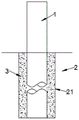
fig. 1 is a sectional elevation view of a simple foundation pile structure according to an embodiment of the present invention;
fig. 2 is a plan view of a simple foundation pile structure according to an embodiment of the present invention;
fig. 3 is a vertical sectional view of a temporary trestle pile supporting structure according to an embodiment of the present invention;
fig. 4 is a top view of a temporary trestle pile supporting structure in an embodiment of the present invention;
fig. 5 is a partial enlarged view of a in fig. 4 according to the present invention;
fig. 6 is a schematic diagram illustrating the operation of a drilling machine in the construction process of the simple foundation pile according to an embodiment of the present invention;
fig. 7 is a schematic moving diagram of a drilling machine for a simple foundation pile construction process according to an embodiment of the present invention;
fig. 8 is a process flow diagram of a construction process of a simple foundation pile according to an embodiment of the present invention;
reference numerals: 1. foundation piles; 2. a riverbed; 3. an anchoring layer; 4. a temporary support; 5. auxiliary piles; 6. a conduit; 7. anchoring the material; 8. a barge; 9. passing through a ship plate; 10. a drilling machine; 11. river banks;
21. pile foundation holes; 22. a temporary pile hole; 41. a support beam; 42. a cross beam;
61. a hopper; 81. a weight box; 82. positioning the pile; 83. and (4) an anchor chain.
Detailed Description
Reference will now be made in detail to the embodiments of the present invention, examples of which are illustrated in the accompanying drawings, wherein like reference numerals refer to the same or similar elements or elements having the same or similar functions throughout. The embodiments described below by referring to the drawings are exemplary only for explaining the present invention, and should not be construed as limiting the present invention.
As shown in fig. 1-2, the utility model provides a simple foundation pile structure, which comprises a pile foundation hole 21 for digging on a riverbed 2 and a foundation pile 1 inserted in the pile foundation hole 21; and an anchoring layer 3 is poured around the inner side wall of the pile foundation hole 21 and the outer side wall of the foundation pile 1.
The anchoring layer 3 is poured between the outer wall of the foundation pile 1 and the side wall of the pile foundation hole 21, the anchoring layer 3 only anchors the foundation pile 1 outside the foundation pile 1, no reinforcing cage, profile steel and other parts are arranged inside the foundation pile 1 for reinforcement connection, and no anchoring concrete is poured, so that a typical friction end bearing pile structure is formed, bending resistance is born by the foundation pile 1 body, the anchoring layer 3 and the soil layer below the pile end bear heavy pressure, the foundation pile 1 and the anchoring layer 3 are stressed clearly, the characteristics of strong bending resistance of the large-diameter foundation pile 1, high compressive strength of the anchoring layer 3 and the like are fully exerted, compared with a pile planting method, the depth of the pile foundation hole 21 in the foundation pile structure is shallow, the depth of the lower end embedded part of the foundation pile 1 is shallow, and in the later stage, part of the foundation pile 1 above the river bed 2 can be recycled, no adverse effect is generated on the waterway, the foundation pile 1 is firmly connected with the river bed 2 and can be recycled, and the passage of the waterway is prevented from being influenced.
Wherein, the anchoring layer 3 is a concrete member with certain connection strength and bearing strength formed by concreting underwater concrete.
In a further improvement, the bottom surface of the foundation pile 1 abuts against the bottom surface of the pile foundation hole 21.
In practical application, the end of the foundation pile 1 abuts against the bottom surface of the pile foundation hole 21, the gravity of the building is transmitted to a firm soil layer or rock through the rolling of the foundation pile 1, and the soil layer under the pile end plays a corresponding supporting role, so that the foundation pile structure has a relatively excellent pressure-bearing effect.
In a further improvement of this embodiment, the foundation pile 1 is a circular pipe structure, and the pile foundation hole 21 is a circular hole matching the outer shape of the foundation pile 1.
The round pipe has the advantages of material saving, light dead weight, large surface area, low cost, strong operation operability, uniform stress and the like compared with a square pipe and a special pipe.
In some embodiments, the diameter ratio of the foundation pile 1 to the pile foundation hole 21 ranges from 1.
In some embodiments, the ratio of the thickness of the foundation pile 1 to the diameter of the pile foundation hole 21 is 2.
In a specific implementation, the foundation pile 1 is made of steel.
The foundation pile 1 is a steel pipe pile with a diameter of 820 x 10, the radius of the pile foundation hole 21 is 1.5m, and the anchoring layer 3 is C30 concrete.
The foundation pile 1 is specifically a steel pipe pile, and the characteristics of batch standardization of the steel pipe pile on the market are utilized, so that the foundation pile 1 in the foundation pile structure is easy to purchase and relatively low in cost, and in operation and construction, compared with the foundation pile 1 used in a pile planting method, a concrete pile does not need to be cast in situ through a pile casing, and the construction convenience and the construction efficiency are improved.
As a further improvement of this embodiment, the casting height of the anchoring layer 3 is equal to the depth of the pile foundation hole 21, and the material of the anchoring layer 3 is underwater concrete.
The pouring height of the anchoring layer 3 is equal to the depth of the pile foundation hole 21, the anchoring layer 3 fills and levels the pile foundation hole 21, the connection effect of the foundation pile 1 and the pile foundation hole 21 is enhanced, meanwhile, the anchoring layer 3 is prevented from overflowing to the outside of the pile foundation hole 21, the anchoring layer 3 is not fixed with the foundation pile 1 at the position above the riverbed 2, and the difficulty of disassembling and recovering the part of the foundation pile 1 above the riverbed 2 is reduced.
Preferably, the depth of the pile foundation hole 21 is not less than 4m.
This technical scheme still provides a simple and easy foundation pile system, including the riverbed 2, still include as above simple and easy foundation pile structure, dig on the riverbed 2 and be equipped with stake foundation hole 21, foundation pile 1 assigns in stake foundation hole 21, and passes through anchoring layer 3 with riverbed 2 relatively fixed.
In the use effect, the foundation pile structure can be arranged on a creek, a river valley, a shoal and other places, is applied to the geology of a shallow covering layer and a bare rock surface, is firmly connected with the riverbed 2, can be recycled, avoids influencing the passage of a navigation channel, and has excellent comprehensive performance.
This technical scheme still provides a trestle, including the bridge, lay the bridge floor on the top surface of bridge, still include as above simple and easy foundation pile structure, foundation pile 1 interval is arranged in the bottom of bridge, and is connected with the bottom of bridge.
In the in-service use, the substructure of landing stage adopts simple and easy foundation pile structure, and bridge floor and bridge on the landing stage pass through 1 firm connections of foundation pile on the riverbed 2, and when the landing stage was demolishd in the later stage or adjustment landing stage structure, also can demolish the recovery with the part foundation pile 1 that is located above the riverbed 2, improve the resource recovery rate, avoid influencing the channel current.
As shown in fig. 3-5, the present technical solution further provides a temporary trestle pile supporting structure, including a foundation pile 1 for vertically placing in a pile foundation hole 21, a temporary pile hole 22 for digging on a river bed 2, an anchoring material 7 filled in the temporary pile hole 22, and an auxiliary pile 5 for positioning the foundation pile 1 in the pile foundation hole 21; the auxiliary piles 5 are embedded in the anchoring materials 7 and fixed with the foundation piles 1.
In practical application, only need dig on riverbed 2 and establish interim stake hole 22, with auxiliary pile 5 cube in interim stake hole 22, backfill afterwards anchor material 7 such as grit, until anchor material 7 fills up interim stake hole 22, auxiliary pile 5 is through anchor material 7 temporary anchoring on riverbed 2, then foundation pile 1 and auxiliary pile 5 reciprocal anchorage of putting immediately on pile foundation hole 21, accomplish foundation pile 1 and fix a position in interim stake hole 22, provide high-quality construction basis for follow-up concreting under water, realize simplifying the temporary support structure of stack bridge pile, reduce the operation engineering volume and demolish the degree of difficulty, thereby improve the efficiency of construction.
Referring to fig. 3, the further improvement further comprises a conduit 6 for pouring the anchoring layer 3 extending between the side wall of the pile foundation hole 21 and the outer wall of the foundation pile 1.
Through setting up pipe 6, utilize pipe 6 with concrete water conservancy diversion under water to between the lateral wall in temporary pile hole 22 and the outer wall spare of foundation pile 1, make the concrete under water fill temporary pile hole 22 to become anchoring layer 3 at the downthehole consolidation of stake, avoid anchoring layer 3 to pour the position more than riverbed 2, realize accurate pouring.
In actual pouring, the distance between the lower port of the guide pipe 6 and the upper port of the pile foundation hole 21 is at least two meters, and after underwater concrete is poured, the depth of the lower port of the guide pipe 6 embedded into the underwater concrete is guaranteed to be not less than 2m, and the pouring quality of the underwater concrete is guaranteed.
And after the underwater concrete is poured, removing the guide pipe 6, fixing the foundation pile 1 in the pile foundation hole 21 after the underwater concrete is solidified into the anchoring layer 3, wherein the depth of the underwater concrete around the foundation pile 1 needs to be measured by using a measuring rope before the high end is removed, and the depth of the lower port of the guide pipe 6 embedded in the underwater concrete is confirmed to be more than two meters.
Referring to fig. 4, a further modification, further includes a temporary support 4; the auxiliary piles 5 and the foundation piles 1 are connected with each other by temporary supports 4, and the guide pipes 6 are erected on the temporary supports 4.
The auxiliary piles 5 and the foundation piles 1 are connected in a mode of building the temporary supports 4, so that walkways for workers to walk are formed between the auxiliary piles 5 and the foundation piles 1, and the workers can conveniently exchange construction operation between the auxiliary piles 5 and the foundation piles 1.
In addition, the auxiliary piles 5 and the foundation piles 1 can be respectively sleeved with a pile casing, and the two pile casings are connected in a positioning mode through cross braces.
In some embodiments, the foundation piles 1 are provided with an even number, and every two foundation piles 1 are symmetrically arranged by taking the auxiliary pile 5 as a center; the number of the temporary supports 4 is several, and every two symmetrically arranged foundation piles 1 are connected with the auxiliary piles 5 through the corresponding one of the temporary supports 4.
Auxiliary pile 5 arranges on central point between two foundation piles 1 puts, and two foundation piles 1 fix a position respectively in the stake foundation hole 21 that corresponds through common a temporary stand 4, reduce steel materials and construction work volume, make things convenient for the worker to walk about making a round trip at two foundation piles 1 simultaneously, facilitate for the construction.
In a specific implementation, the temporary supports 4 extend along a straight line and are respectively connected to two corresponding foundation piles 1.
As a further improvement of the embodiment, a plurality of the temporary supports 4 are all at the same level and are connected in an intersecting manner.
A plurality of temporary support 4 erects on same level, and crossing connection, and different temporary support 4 interconnect forms the pavement that switches on each other, and the workman can follow auxiliary pile 5 department, walks to arbitrary foundation pile 1 department, provides construction convenience for watering in succession and builds a pile foundation hole 21.
Referring to fig. 5, the temporary support 4 has a specific structure that the temporary support 4 includes two support beams 41 arranged at intervals, and a pipe fixing frame spanned between the two support beams 41; the auxiliary piles 5 and the foundation piles 1 are located between the two support beams 41 and are connected with the support beams 41 on the two sides; the guide pipe 6 is connected with the pipeline fixing frame.
The temporary support 4 further includes a cross brace located between the two support beams 41 for a worker to step on and walk, the cross brace is arranged along the length intervals of the support beams 41 and is connected with the support beams 41 on both sides, and the cross brace is arranged between the auxiliary pile 5 and the foundation pile 1.
The specific structure of the pipeline fixing frame is that the pipeline fixing frame comprises two cross beams 42 which are arranged at intervals; the ends of the two cross beams 42 are respectively connected with the corresponding support beams 41, and the conduit 6 is located between the two cross beams 42 and connected with the cross beams 42 at two sides.
The two beams 42 are arranged on the two support beams 41 in a staggered manner, the beams 42 on both sides are arranged on the opposite sides of the guide pipe 6 and connected with the guide pipe 6, and the beams 42 on both sides clamp the guide pipe 6 to fix the guide pipe 6 on the temporary support 4.
This technical scheme can provide a landing stage stake crowd, include riverbed 2, dig the stake foundation hole 21 of establishing on riverbed 2, still include as above the interim bearing structure of landing stage stake, dig on the riverbed 2 and be equipped with interim stake hole 22, foundation pile 1 is fixed in the stake foundation hole 21.
Pile foundation holes 21 and temporary pile holes 22 are dug at intervals on the riverbed 2, auxiliary piles 5 are fixed in the temporary pile holes 22 through anchoring materials 7, foundation piles 1 and auxiliary piles 5 are fixed to each other and fixed in the pile foundation holes 21, the auxiliary piles 5 and the plurality of foundation piles 1 jointly form a trestle pile group, and support is provided for subsequent construction of a trestle.
Before pile foundation hole 21 is at installation foundation pile 1, need adopt to dig soon to having crept into to design standard height pile foundation hole 21 and dig by the secondary, the sediment that drills in clearance backward flow to pile foundation hole 21, guarantee foundation pile 1 can insert to predetermineeing the degree of depth, and in concrete operation, after the sediment was bored in the clearance, the pile foundation inserted pile foundation hole 21, and the terminal surface of the lower extreme of foundation pile 1 supports tightly on the bottom in pile foundation hole 21.
In a specific implementation, an anchoring layer 3 is cast around between the side wall of the pile foundation hole 21 and the outer wall of the foundation pile 1.
Through pouring the concrete under water in pile foundation hole 21, the concrete under water fills between the outer wall of foundation pile 1 and the lateral wall in pile foundation hole 21, and after the concrete under water concreted into anchoring layer 3, anchoring layer 3 fixed foundation pile 1 in pile foundation hole 21, alright demolish temporary stand 4 and pull out auxiliary pile 5.
As shown in fig. 8, the utility model provides a construction process of simple foundation pile, including following construction steps:
arranging temporary pile holes 22 and pile foundation holes 21 for digging on the river bed 2;
inserting an auxiliary pile 5 into the temporary pile hole 22, and backfilling the anchoring material 7 into the temporary pile hole 22;
the foundation pile 1 is inserted into the pile foundation hole 21 and fixed with the auxiliary pile 5;
and pouring the anchoring layer 3 in the pile foundation hole 21, wherein the anchoring layer 3 is filled between the side wall of the pile foundation hole 21 and the outer wall of the foundation pile 1 in a surrounding manner, and the foundation pile 1 is fixed in the pile foundation hole 21.
Fig. 8 is combined with fig. 3-7, and the implementation manner is that only the temporary pile hole 22 needs to be dug on the riverbed 2, the auxiliary pile 5 is cubed in the temporary pile hole 22, then the anchoring material 7 such as gravel is backfilled until the temporary pile hole 22 is filled with the anchoring material 7, the auxiliary pile 5 is temporarily anchored on the riverbed 2 through the anchoring material 7, then the foundation pile 1 vertically placed on the pile foundation hole 21 and the auxiliary pile 5 are mutually fixed, so that the foundation pile 1 is positioned in the temporary pile hole 22, a high-quality construction foundation is provided for the subsequent pouring of underwater concrete, and the trestle pile is quickly formed only through three main processes of drilling, pile erecting, concrete pouring and the like.
When burying many foundation piles 1 underground, many foundation piles 1 simultaneously or in proper order with supplementary stake 5 fixed, toward pouring anchor layer 3 in the pile foundation hole 21 that corresponds, form the foundation pile crowd of compriseing many foundation piles 1.
In the implementation operation, after the anchoring layer 3 is poured in the pile foundation hole 21, the method further comprises the following construction steps:
and after the anchoring layer 3 reaches a preset strength value, the foundation pile 1 is released from being fixed with the auxiliary pile 5, and the auxiliary pile 5 is pulled out.
In some embodiments, before inserting said foundation pile 1 into pile foundation hole 21, the following construction steps are also included:
and (4) carrying out secondary excavation on the pile foundation hole 21 drilled to the designed elevation, and cleaning drilling slag flowing back to the pile foundation hole 21.
Digging a pile foundation hole 21 through the secondary, removing foreign matters such as drilling slag and the like, preventing the foundation pile 1 from being supported by the foreign matters, ensuring that the foundation pile 1 can be inserted to a preset depth, enabling the end surface of the lower end of the foundation pile 1 to be tightly supported on the bottom of the pile foundation hole 21, transmitting the gravity of a building to a firm soil layer or rock through rolling of a pile body, supporting the soil layer below the pile end correspondingly, and improving the pile forming quality and the bearing strength of the foundation pile 1 by the construction process.
Referring to fig. 3, in some embodiments, before the pouring of the anchoring layer 3 in the pile foundation hole 21, the following steps are further included:
a conduit 6 for casting the anchoring layer 3 is arranged, the lower port of the conduit 6 extending between the inner wall of the pile foundation hole 21 and the outer wall of the foundation pile 1.
Through arranging the guide pipe 6, the accurate pouring of fixed point is fixed a position, with the underwater concrete water conservancy diversion to between the lateral wall of stake foundation hole 21 and the outer wall of foundation pile 1, avoid underwater concrete to fall on the riverbed 2 of stake foundation hole 21 periphery, prevent that underwater concrete from consolidating with foundation pile 1 on riverbed 2, improve the quality of pouring the shaping simultaneously.
In practical application, after the arrangement of the conduit 6 for casting the anchoring layer 3, the following construction steps are also included:
underwater concrete which can be fixed to the anchoring layer 3 is loaded into the hopper 61, and the hopper 61 is hung over the upper end of the guide pipe 6.
Through adopting hopper 61 and the cooperation of pipe 6, the concrete falls into pipe 6 from hopper 61 under the effect of gravity under, along pipe 6 in falling to pile foundation hole 21, only reaches the transport effect through the dead weight of concrete under water, need not to adopt construction appliances such as pumps to assist, has reduced the work load of settling appurtenance, has reduced the required energy resource consumption of construction.
In practical operation, the pouring of the anchoring layer 3 in the pile foundation hole 21 includes the following construction steps:
when the underwater concrete in the hopper 61 completely fills the pile foundation hole 21 through the guide pipe 6, the guide pipe 6 is pulled out from the pile foundation hole 21, and the underwater concrete is waited to be consolidated into the anchoring layer 3.
The guide pipe 6 is pulled out after the underwater concrete is poured, so that the guide pipe 6 is prevented from being anchored in the pile foundation hole 21 after the underwater concrete is solidified, and meanwhile, the forming quality of the underwater concrete solidified into the anchoring layer 3 is prevented from being influenced.
In a further improvement, when the guide pipe 6 is pulled out from the pile foundation hole 21, the following construction steps are further included:
and measuring the depth of the underwater concrete around the foundation pile 1 by using a measuring rope, and confirming the depth of the lower port of the guide pipe 6 embedded into the underwater concrete.
In actual construction, the lower port of the guide pipe 6 is buried into underwater concrete to a depth of more than two meters, and then the high-quality anchoring layer 3 can be poured.
In some embodiments, when the number of the pile foundation holes 21 is even, every two foundation piles 1 are symmetrically arranged centering on the auxiliary pile 5 and are both fixed to the auxiliary pile 5.
The plurality of foundation piles 1 are symmetrically arranged on the two opposite sides of the auxiliary pile 5, so that the number of the auxiliary piles 5 can be reduced, and a foundation pile group consisting of the plurality of foundation piles 1 can be constructed by one auxiliary pile 5.
Referring to fig. 2, in a specific operation, when the auxiliary pile 5 is connected with the foundation pile 1, the following construction steps are further included:
and building temporary supports 4, wherein every two symmetrically arranged foundation piles 1 are connected with the auxiliary piles 5 through the corresponding temporary supports 4.
The auxiliary pile 5 is arranged on the central position between the two foundation piles 1, the two foundation piles 1 are respectively positioned in the corresponding pile foundation holes 21 through a common temporary support 4, the steel material consumption and the construction engineering amount are reduced, and meanwhile, the auxiliary pile facilitates the worker to walk back and forth at the two foundation piles 1, so that convenience is brought to construction.
Referring to fig. 7, in some embodiments, before the arrangement for excavating the temporary pile hole 22 and the pile foundation hole 21 provided on the river bed 2, the following construction steps are further included:
the drill 10 is transported to a predetermined construction site by the barge 8, and the drill 10 digs the temporary piling hole 22 and the piling hole 21.
In a specific operation, when the drilling machine 10 is transported to a preset construction position through the barge 8, the following construction steps are further included:
a drill 10 is attached to the barge 8 to be fixed to the barge 8.
In actual operation, 4 steel sections forming an angle of 45 degrees with the deck of the barge 8 are arranged, and ring steel members in the crawler of the drilling machine 10 are welded and fixed with the barge 8 through the steel sections.
In the construction work, when the drilling machine 10 is transported to a preset construction position by the barge 8, the construction method further comprises the following construction steps:
the barge 8 is positioned at a preset construction position by a chain 83 for connection with a ground anchor and a spud 82 for insertion on the river bed 2.
In practical application, the barge 8 is provided with the weight box 81, the barge 8 keeps the hull of the ship stable through the weight box 81, the excessive load on the side where the drilling machine 10 is placed is prevented, the construction stability of the drilling machine 10 is improved, and the hole digging quality is improved.
In the specific implementation, the pile foundation hole 21 and the temporary pile hole 22 are dug by adopting a rotary drilling construction process, when the soil layer of the riverbed 2 has good cohesiveness, a dry or clean water drilling process can be adopted, and mud is not needed for wall protection; when the soil layer of the river bed 2 is loose and easy to collapse, a static mud retaining wall drilling process is adopted, and retaining wall mud or stabilizing liquid is put into the holes for wall protection.
Referring to fig. 6, in some embodiments, before the drilling machine 10 is transported to a preset construction position by the barge 8, the following construction steps are further included:
the barge 8 is parked at the bank 11, a ship plate 9 is erected between the barge 8 and the bank 11, and a drilling machine 10 is moved to the barge 8 through the ship plate 9.
In the specific implementation, when the barge 8 stops on the shore, the construction method further comprises the following construction steps:
the barge 8 is positioned at the bank 11 by a chain 83 for connection with a ground anchor and a spud 82 for insertion on the river bed 2.
Wherein the water depth of the river bank 11 side is about 1.5m, and the requirement of 8 drafts of the barge is met; the barge 8 is provided with a spud 82 for driving on the river bed 2 and an anchor chain 83.
In addition, the weight box 81 and the drilling machine 10 can be moved to the barge 8 by the penetration plate, and the weight box 81 and the drilling machine 10 can be transported to the barge 8 by a hoisting method, which is not limited in this embodiment.
The weight box 81 is filled with slag, and the weight of the weight box 81 can be adjusted by adding or reducing the slag in the weight box 81, so that the weight box is suitable for drilling machines 10 with different tonnages.
In the implementation operation, the river bank 11 is hardened to form a hardened driving band, the steel plate is embedded in the hardened driving band, and the ship passing plate 9 is welded with the steel plate to realize the connection of the ship passing plate 9 and the river bank 11.
Compared with the prior art, the utility model discloses a scheme has following advantage:
the construction process of the simple foundation pile structure adopted by the technical scheme has the characteristics of simple process and simple operation, only comprises three main processes of drilling, pile erecting, concrete pouring and the like, can be pushed in parallel among the three processes, and has higher pile forming speed.
According to the technical scheme, the anchoring layer 3 (underwater concrete) and the riverbed 2 rock mass are connected into a whole, the characteristics of roughness, high strength, high bearing capacity and the like of the rock mass surface are fully utilized, the anchoring depth is not required to be as deep as that of a pile planting method in a pile, and the foundation pile 1 is not required to be added to form a stable structure system like a bench pile, so that the mechanical requirements of the trestle pile such as bending resistance, slippage resistance, overturning resistance, vertical bearing capacity and the like can be met.
The technical scheme not only shortens the pile length and improves the pile forming efficiency, but also recycles part of the foundation piles 1 above the riverbed 2, saves the steel pipe pile material and does not have adverse effect on the channel after being dismantled.
In the bare rock surface riverbed 2 and in the environment with fast water flow velocity, the trestle tubular pile is externally anchored with concrete only by drilling, erecting and water system tubular piles, the process is simple, the construction operation is simple and convenient, and the mechanical requirements of the trestle pile such as bending resistance, overturning resistance, vertical bearing capacity and the like can be met.
The foregoing is only a partial embodiment of the present invention, and it should be noted that, for those skilled in the art, a plurality of modifications and decorations can be made without departing from the principle of the present invention, and these modifications and decorations should also be regarded as the protection scope of the present invention.
Claims (10)
1. A simple foundation pile structure is characterized by comprising a pile foundation hole which is used for digging on a riverbed and a foundation pile which is inserted in a pile foundation hole; and an anchoring layer is poured around the part between the inner side wall of the pile foundation hole and the outer side wall of the foundation pile.
2. The simple foundation pile structure of claim 1, wherein the bottom surface of the foundation pile abuts against the bottom surface of the pile foundation hole.
3. The simple foundation pile structure of claim 1, wherein the foundation pile is a circular tube structure, and the pile foundation hole is a circular hole matching the outer shape of the foundation pile.
4. The simple foundation pile structure of claim 3, wherein the diameter ratio of the foundation pile to the pile foundation hole is in the range of 1.
5. The simple foundation pile structure of claim 3, wherein the ratio of the thickness of the foundation pile to the diameter of the pile foundation hole is 2.
6. The simple foundation pile structure according to claim 3, wherein the foundation pile is made of steel.
7. The simple foundation pile structure of claim 1, wherein the casting height of the anchoring layer is equal to the depth of the pile foundation hole, and the anchoring layer is made of underwater concrete.
8. The simple foundation pile structure of claim 1, wherein the depth of the pile foundation hole is not less than 4m.
9. A simple foundation pile system comprising a riverbed, characterized by further comprising the simple foundation pile structure according to any one of claims 1 to 8, wherein the riverbed is excavated with the pile foundation hole, and the foundation pile is inserted into the pile foundation hole and fixed relative to the riverbed through the anchoring layer.
10. A trestle comprising a bridge and a bridge deck laid on the top surface of the bridge, and further comprising the simple foundation pile structure as claimed in any one of claims 1 to 8, wherein the foundation piles are arranged at intervals on the bottom of the bridge and connected with the bottom of the bridge.
Priority Applications (1)
| Application Number | Priority Date | Filing Date | Title |
|---|---|---|---|
| CN202221996528.5U CN218148482U (en) | 2022-07-29 | 2022-07-29 | Simple foundation pile structure, system thereof and trestle |
Applications Claiming Priority (1)
| Application Number | Priority Date | Filing Date | Title |
|---|---|---|---|
| CN202221996528.5U CN218148482U (en) | 2022-07-29 | 2022-07-29 | Simple foundation pile structure, system thereof and trestle |
Publications (1)
| Publication Number | Publication Date |
|---|---|
| CN218148482U true CN218148482U (en) | 2022-12-27 |
Family
ID=84596977
Family Applications (1)
| Application Number | Title | Priority Date | Filing Date |
|---|---|---|---|
| CN202221996528.5U Active CN218148482U (en) | 2022-07-29 | 2022-07-29 | Simple foundation pile structure, system thereof and trestle |
Country Status (1)
| Country | Link |
|---|---|
| CN (1) | CN218148482U (en) |
-
2022
- 2022-07-29 CN CN202221996528.5U patent/CN218148482U/en active Active
Similar Documents
| Publication | Publication Date | Title |
|---|---|---|
| CN104612162B (en) | A kind of Deep Foundation Pit of Metro Stations excavation construction method | |
| CN101864773B (en) | Deep foundation pit support process | |
| CN102953341B (en) | A kind of high-order trestle work structure be arranged in deep water torrent intectate steep bare rock | |
| CN204491626U (en) | The foundation pit enclosure structure that Larsen steel sheet pile and prestressed anchor combine | |
| US20140026518A1 (en) | Construction method for root-type foundation anchorage and bored, root-type cast in-situ pile with anchor bolts | |
| CN109024651B (en) | Steel pipe concrete mixed pile foundation and construction method | |
| CN102979039B (en) | Elevated trestle bridge construction method on covering-free steep bare rock in deepwater and rapid stream | |
| CN100510281C (en) | Semi-inverse construction method of super large diameter, ultra-burial depth storage pond | |
| CN103321246A (en) | Underground diaphragm wall based foundation pit construction method | |
| CN107642041A (en) | The hollow clump of piles anchorage of super-large diameter | |
| CN106948340A (en) | A kind of construction method of the Manual excavated pile structure of high polymer grouting protection | |
| CN113174958A (en) | Construction method for foundation pit of adjacent road under poor ground condition | |
| CN203049443U (en) | High level trestle structure arranged on steep bare rock of deepwater torrent unsheathed layer | |
| CN111851588A (en) | Pipe jacking well structure and construction method thereof | |
| CN106758759B (en) | A kind of trestle pile foundation and its anchoring process for deep water drift net riverbed | |
| CN104164881A (en) | Piling wall overlapping cantilever foundation pit support construction method and structure | |
| CN107165173A (en) | A kind of foundation pit supporting system and its construction method | |
| CN114575355A (en) | Soil protection and descent construction method | |
| CN109610473A (en) | A kind of construction method of the large-scale pool structure foundation pit supporting system of municipal administration | |
| CN207484290U (en) | The hollow clump of piles anchorage of super-large diameter | |
| CN113431065A (en) | Rapid construction method and structure of occlusive pile and steel sleeve combined cofferdam | |
| CN110055973B (en) | Foundation pit enclosure structure under high-speed railway bridge with limited construction space and water stopping method | |
| CN105239573B (en) | The interplantation tube anchor rock construction method of shaped steel trestle | |
| CN111549789A (en) | Reinforcing structure for foundation pit support and construction method thereof | |
| CN106498957A (en) | Steel sheet pile cofferdam construction platform and integral construction method |
Legal Events
| Date | Code | Title | Description |
|---|---|---|---|
| GR01 | Patent grant | ||
| GR01 | Patent grant |