CN218026949U - Device is pour in piecemeal to integral sunshade of high-speed railway - Google Patents
Device is pour in piecemeal to integral sunshade of high-speed railway Download PDFInfo
- Publication number
- CN218026949U CN218026949U CN202222317601.8U CN202222317601U CN218026949U CN 218026949 U CN218026949 U CN 218026949U CN 202222317601 U CN202222317601 U CN 202222317601U CN 218026949 U CN218026949 U CN 218026949U
- Authority
- CN
- China
- Prior art keywords
- pipe
- spiral
- motor
- outer truss
- electric valve
- Prior art date
- Legal status (The legal status is an assumption and is not a legal conclusion. Google has not performed a legal analysis and makes no representation as to the accuracy of the status listed.)
- Active
Links
Images
Abstract
A block pouring device for an integral curtain board of a high-speed railway comprises an outer truss, a control box, a traveling motor, a stirring motor and a spiral guide pipe bolt, wherein the traveling motor drives rubber traveling wheels to move forwards, the stirring motor drives stirring blades to rotate, a discharging pipe is in bolt connection with the spiral guide pipe, and an electric valve is in bolt connection with a node position below the discharging pipe and above the spiral guide pipe. The railway integral type concrete covering plate has the advantages of simple structure, low cost, strong operation applicability, self-walking, safety and reliability, and is suitable for railway integral type concrete covering plate engineering.
Description
Technical Field
The utility model discloses concrete construction technical field relates to the integral sunshade concrete construction machines of railway box girder, concretely relates to device is pour to the integral sunshade piecemeal of high-speed railway.
Background
Adopt integral sunshade among the railway engineering bridge deck system at present, the vertical polylith of sunshade is pour, pours the feed inlet less, because of the sunshade highly reaches 2 meters, adopts the construction mode of half underground formula concreting, is about to put into the underground for 3 integral sunshade templates major parts, puts into the small hopper through the concrete tank car with the material, progressively carries out the construction after hoisting with fork truck, has that the construction is slow and the cloth is inhomogeneous, occupies tank car chronic scheduling problem.
In view of the above-mentioned defect, how to solve the integral formula of railway case roof beam and hide board concrete engineering construction cloth, ensure that the construction progress satisfies the demands, improve the cloth quality, need a novel structure and solve the interim storage and pour the blowing difficult problem of the integral formula of railway case roof beam and hide board concrete engineering construction concrete.
Disclosure of Invention
In order to overcome the not enough of above-mentioned prior art, the utility model aims at providing a device is pour to integral sunshade piecemeal of high-speed railway, it has simple structure, and is with low costs, easily operation, and the security is good, the good characteristics of commonality.
In order to achieve the above purpose, the technical scheme of the utility model is as follows:
the utility model provides a device is pour to integral sunshade piecemeal of high-speed railway, including outer truss 4, its characterized in that, outer truss 4 and control box 3, walk capable motor 2, agitator motor 6, 8 bolted connections of spiral pipe, walk capable motor 2 drive the rubber of outer truss 4 bottom and walk capable wheel 1, agitator motor 6 drive stirring leaf 5 fixed above outer truss 4 rotates, blowing pipe 9 is bolted below spiral pipe 8 of outer truss 4 middle part triangle structure below, spiral pipe 8 both ends set up spiral motor 10, blowing electric valve 11 is bolted on blowing pipe 9, electric valve 7 is bolted on spiral pipe 8 upper portion triangle structure.
The outer truss 4 is a square four-leg tank body, and the lower part of the tank body is triangular.
The spiral guide pipe 8 be circular steel pipe, spiral guide pipe 8 lower part sets up 3 blowing pipes 9, every blowing pipe 9 is equipped with a blowing electric valve 11, blowing electric valve 11 sets up in blowing pipe 9 top and spiral guide pipe 8 below department, is connected with the control box through the circuit, but centralized control switch.
The control box 3 is connected with the walking motor 2, the stirring motor 6, the electric valve 7, the spiral motor 10 and the discharging electric valve 11 through electric wires.
The utility model has the advantages that:
1) Through the combination of the material storage tank body capable of electrically walking and the electric stirring, the purposes of storing and transporting a plurality of blocks of integral shutter concrete to a pouring station for operation are achieved.
2) The concrete is transmitted to each discharge port through the spiral guide pipe, and the purpose of one-port and multi-port distribution is achieved.
3) The cooperation of electrically operated valve and spiral pipe can carry out even cloth simultaneously to three integral sunshade boards once, and the precision of efficiency of construction and cloth concrete volume has all obtained improving by a wide margin.
4) Simple structure, with low costs, convenient to use is swift, operates safe and reliable, can electric drive, practices thrift the cost, has reduced the potential safety hazard, is applicable to the integral formula of railway box girder apron concrete engineering construction.
Drawings
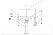
Fig. 1 is a front schematic view of the present invention;
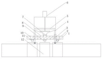
fig. 2 is a schematic side view.
Wherein, 1 is a rubber walking wheel, 2 is a walking motor, 3 is a control box, 4 is an outer truss, 5 is a stirring blade, 6 is a stirring motor, 7 is an electric valve, 8 is a spiral conduit, 9 is a discharging pipe, 10 is a spiral motor, 11 is a discharging electric valve, and 12 is an integral type shielding plate template.
Detailed Description
The present invention will be further described with reference to the accompanying drawings.
As shown in fig. 1 and 2, the block pouring device for the integral curtain board of the high-speed railway comprises an outer truss 4 and is characterized in that the outer truss 4 is bolted with a control box 3, a traveling motor 2, a stirring motor 6 and a spiral conduit 8, the traveling motor 2 drives a rubber traveling wheel 1 at the bottom of the outer truss 4, the stirring motor 6 fixed above the outer truss 4 drives a stirring blade 5 to rotate, a discharging pipe 9 is bolted below the spiral conduit 8 below a triangular structure in the middle of the outer truss 4, the spiral motors 10 are arranged at two ends of the spiral conduit 8, a discharging electric valve 11 is bolted on the discharging pipe 9, and an electric valve 7 is bolted on a triangular structure on the upper portion of the spiral conduit 8.
The outer truss 4 is a square four-leg tank body, and the lower part of the tank body is triangular.
The spiral guide pipe 8 is a circular steel pipe, 3 discharging pipes 9 are arranged on the lower portion of the spiral guide pipe 8, each discharging pipe 9 is provided with a discharging electric valve 11, and the discharging electric valves 11 are arranged above the discharging pipes 9 and below the spiral guide pipe 8 and connected with the control box through circuits, so that the switch can be controlled in a centralized mode.
The control box 3 is connected with the walking motor 2, the stirring motor 6, the electric valve 7, the spiral motor 10 and the discharging electric valve 11 through electric wires.
The utility model discloses a theory of operation is:
before the device is used, the device is assembled and debugged to be qualified, the device is washed by clear water, the device is powered on, the electric valves are switched on one by one, the device stirs She Jiaodong, a walking motor runs back and forth for a plurality of times, a concrete tanker transports concrete to a construction site, an operator controls the walking motor to drive a rubber walking wheel driving device to enter a material placing area through a control box operating device, the rubber walking wheel driving device is driven by the walking motor to enter the material placing area, the concrete is placed into a material placing pipe according to the concrete dosage of 3 integral curtain board templates, the stirring motor is started through the control box to drive stirring blades to stir the concrete, the walking motor drives the rubber walking wheel driving device to enter the upper part of the integral curtain board templates, 3 electric valves are started, a screw motor is started, the concrete is conveyed to 3 material placing pipes, the electric valves are opened to place the curtain board, the curtain board is placed, after all the 3 boards are poured, the device moves forward, the integral curtain board is hoisted out of the operation area, the next batch of the device is poured, the device is continuously operated, and the device is cleaned after all the plates are finished.
Claims (4)
1. The utility model provides a device is pour to integral sunshade piecemeal of high-speed railway, including outer truss (4), a serial communication port, outer truss (4) and control box (3), walk capable motor (2), agitator motor (6), spiral pipe (8) bolt, walk capable motor (2) rubber of drive outer truss (4) bottom and walk capable wheel (1), agitator motor (6) drive stirring leaf (5) that outer truss (4) top is fixed rotate, blowing pipe (9) bolt is in spiral pipe (8) below outer truss (4) middle part triangular structure, spiral pipe (8) both ends set up spiral motor (10), blowing electric valve (11) bolt is on blowing pipe (9), electric valve (7) bolt is on spiral pipe (8) upper portion triangular structure.
2. The high-speed railway integral curtain plate block pouring device as claimed in claim 1, wherein the outer truss (4) is a square four-leg tank body, and the lower part of the tank body is triangular.
3. The high-speed railway integral curtain plate block pouring device as claimed in claim 1, wherein the spiral guide pipe (8) is a round steel pipe, 3 discharging pipes (9) are arranged at the lower part of the spiral guide pipe (8), each discharging pipe (9) is provided with a discharging electric valve (11), and the discharging electric valves (11) are arranged above the discharging pipes (9) and below the spiral guide pipe (8).
4. The high-speed railway integral cover plate block pouring device according to claim 1, wherein the control box (3) is connected with the traveling motor (2), the stirring motor (6), the electric valve (7), the spiral motor (10) and the discharging electric valve (11) through electric wires.
Priority Applications (1)
| Application Number | Priority Date | Filing Date | Title |
|---|---|---|---|
| CN202222317601.8U CN218026949U (en) | 2022-09-01 | 2022-09-01 | Device is pour in piecemeal to integral sunshade of high-speed railway |
Applications Claiming Priority (1)
| Application Number | Priority Date | Filing Date | Title |
|---|---|---|---|
| CN202222317601.8U CN218026949U (en) | 2022-09-01 | 2022-09-01 | Device is pour in piecemeal to integral sunshade of high-speed railway |
Publications (1)
| Publication Number | Publication Date |
|---|---|
| CN218026949U true CN218026949U (en) | 2022-12-13 |
Family
ID=84351688
Family Applications (1)
| Application Number | Title | Priority Date | Filing Date |
|---|---|---|---|
| CN202222317601.8U Active CN218026949U (en) | 2022-09-01 | 2022-09-01 | Device is pour in piecemeal to integral sunshade of high-speed railway |
Country Status (1)
| Country | Link |
|---|---|
| CN (1) | CN218026949U (en) |
Cited By (1)
| Publication number | Priority date | Publication date | Assignee | Title |
|---|---|---|---|---|
| CN116652510A (en) * | 2023-08-02 | 2023-08-29 | 山西中盈万维耐磨材料有限公司 | Novel fusion welding device for casting processing |
-
2022
- 2022-09-01 CN CN202222317601.8U patent/CN218026949U/en active Active
Cited By (2)
| Publication number | Priority date | Publication date | Assignee | Title |
|---|---|---|---|---|
| CN116652510A (en) * | 2023-08-02 | 2023-08-29 | 山西中盈万维耐磨材料有限公司 | Novel fusion welding device for casting processing |
| CN116652510B (en) * | 2023-08-02 | 2023-10-10 | 山西中盈万维耐磨材料有限公司 | Novel fusion welding device for casting processing |
Similar Documents
| Publication | Publication Date | Title |
|---|---|---|
| CN102241067B (en) | Production line of light weight foam concrete building board | |
| CN218026949U (en) | Device is pour in piecemeal to integral sunshade of high-speed railway | |
| CN209718183U (en) | A kind of concrete slab of Construction of Civil Engineering pours device | |
| CN202498631U (en) | High speed stirring pulping bench vehicle | |
| WO2013067866A1 (en) | Method for pouring self-leveling concrete filler mortar for track slabs | |
| CN210282699U (en) | Self-propelled material distribution equipment | |
| WO2011150850A1 (en) | Mortar transfer device | |
| CN210621405U (en) | Concrete grouting device for road construction | |
| CN111976003A (en) | Concrete stirring process | |
| CN209854569U (en) | Automatic pouring device for bridge deck concrete | |
| CN110820481A (en) | Agitating unit is used in civil engineering construction | |
| CN206765073U (en) | A kind of mandatory stirring drag pump | |
| CN211368442U (en) | Crack filling and reinforcing structure of road and bridge | |
| CN114658479A (en) | Construction method of filling partition wall | |
| CN209478597U (en) | A kind of concrete feeding equipment | |
| CN208828876U (en) | Tank car charging automatic flushing device | |
| CN208343157U (en) | Slurry agitator is used in a kind of construction of building pile foundation | |
| CN211446413U (en) | Self-compaction concrete fills construction equipment | |
| CN207630273U (en) | A kind of high abrupt slope concrete transportation eliminates the secondary stirring device of isolation | |
| CN110815530A (en) | Full-automatic concrete pouring and conveying system | |
| CN215366654U (en) | Road repair mortar processing apparatus | |
| CN215472130U (en) | Prevent raising grey concrete conveyer | |
| CN205471247U (en) | Lifting machine for building engineering | |
| CN208473867U (en) | A kind of slurry can of slurry station storage slurry | |
| CN209837599U (en) | Concrete real-time pouring device for construction site |
Legal Events
| Date | Code | Title | Description |
|---|---|---|---|
| GR01 | Patent grant | ||
| GR01 | Patent grant |