CN217946713U - Take automatic sequencing charging equipment of pier nose clamp plate - Google Patents
Take automatic sequencing charging equipment of pier nose clamp plate Download PDFInfo
- Publication number
- CN217946713U CN217946713U CN202221753341.2U CN202221753341U CN217946713U CN 217946713 U CN217946713 U CN 217946713U CN 202221753341 U CN202221753341 U CN 202221753341U CN 217946713 U CN217946713 U CN 217946713U
- Authority
- CN
- China
- Prior art keywords
- frame
- jacking
- plate
- shaped plate
- equipment
- Prior art date
- Legal status (The legal status is an assumption and is not a legal conclusion. Google has not performed a legal analysis and makes no representation as to the accuracy of the status listed.)
- Active
Links
Images

Landscapes
- Bridges Or Land Bridges (AREA)
Abstract
The utility model relates to the technical field of feeding mechanisms, and discloses an automatic sequencing feeding device with a pier nose pressing plate; this take automatic sequencing charging equipment of pier nose clamp plate includes equipment frame, equipment frame's top is provided with first deflector, first "V" shaped plate, second "V" shaped plate and second deflector, first "V" shaped plate, second "V" shaped plate and second deflector arrange in proper order and be provided with the jacking space between two liang from a left side to the right side, jacking space inner chamber is provided with the jacking board, jacking board bottom is provided with the jacking cylinder, equipment frame right side is provided with the cooperation frame, the cooperation frame inner chamber is provided with two sets of bilateral symmetry's synchronizing wheel, the utility model discloses can realize becoming orderly from unordered arrangement to the cylindric part of the bolt form part of equidimension not, cylindric part and a bandeau clamp plate, it is stronger to the length compatibility of product, and sound is littleer.
Description
Technical Field
The utility model belongs to the technical field of feed mechanism, specifically be an automatic sequencing charging equipment of area pier nose clamp plate.
Background
The pressing plate with the pier head refers to a bolt-shaped part, a cylindrical part and a cylindrical part with a pressing plate, and when the pressing plate is produced or assembled, the pressing plate needs to be loaded and conveyed.
When the existing bolt-shaped parts, the existing cylindrical parts and the existing cylindrical parts with the pressure plates are fed and conveyed, the parts which are stacked out of order are arranged orderly by the principle of a vibration disc, but the existing equipment or mechanisms can only arrange some parts which are out of order, shorter and thinner, in order, such as some vibration discs and bolt feeding machines, and the equipment or mechanisms generally have higher noise and can only arrange some single parts; therefore, improvements are now needed in view of the current situation.
Disclosure of Invention
To the above situation, for overcoming prior art's defect, the utility model provides a take automatic sequencing charging equipment of pier nose clamp plate, the effectual current bolt form part of having solved, cylindric part and the cylindric part of a bandeau clamp plate are when carrying out the material loading and carry, generally arrange unordered part orderly stacking through the vibration dish principle, but current equipment or mechanism can only be some unordered shorter thinner part orderly arrangements, for example some vibration dishes, bolt material loading machine, the general noise of these equipment or mechanism is great, and can only arrange the problem of some single parts.
In order to achieve the above purpose, the utility model provides a following technical scheme: the utility model provides a take automatic sequencing charging equipment of pier nose clamp plate, includes the equipment frame, the top of equipment frame is provided with first deflector, first "V" shaped plate, second "V" shaped plate and second deflector, first "V" shaped plate, second "V" shaped plate and second deflector are ordered in proper order and are provided with the jacking space between two liang from a left side to the right side, jacking space inner chamber is provided with the jacking board, jacking board bottom is provided with the jacking cylinder, equipment frame right side is provided with the cooperation frame, cooperation frame inner chamber is provided with two sets of bilateral symmetry's synchronizing wheel, and the outer wall of two sets of synchronizing wheels is provided with the hold-in range, and two synchronizing wheel looks backs of rear side all are provided with driving motor, cooperation frame right side middle part is provided with the arrangement cylinder.
Preferably, the front and back sides of the first guide plate, the first V-shaped plate, the second V-shaped plate and the second guide plate are provided with side plates, and the bottoms of the two side plates are connected to the top of the equipment frame.
Preferably, the middle part of the equipment frame is provided with an installation cross rod, and the jacking cylinder is connected to the bottom midpoint of the installation cross rod.
Preferably, the front end and the rear end of the right side of the equipment frame are respectively provided with a first mounting frame, and the two first mounting frames are connected with the matching frame.
Preferably, the outer wall of the rear side of the matching frame is provided with a second mounting frame, and the two driving motors are connected to the outer walls of the left side and the right side of the second mounting frame.
Preferably, a baffle is arranged on the right side of the matched frame, and the tidying cylinder is located at the middle point of the right side of the baffle.
Preferably, the first guide plate is obliquely arranged, and the first V-shaped plate, the second V-shaped plate and the second guide plate are distributed in a stepped manner from low to high.
Compared with the prior art, the beneficial effects of the utility model are that:
1. the jacking cylinder ascends to drive the jacking plate to ascend, a part positioned at the top of the jacking plate ascends to fall into the top of the first V-shaped plate, then the jacking cylinder descends to drive the jacking plate to descend to the original position, at the moment, the part positioned at the top of the first V-shaped plate enters the top of the jacking plate along with the inclination angle, the jacking cylinder repeats the ascending and descending steps until the part is conveyed to the second guide plate, the part enters the synchronous belt along with the inclination angle, the synchronous wheel drives the connected synchronous belt to move forwards, the part at the top of the synchronous belt also moves forwards, at the moment, the arranging cylinder drives the matching frame to vibrate, the synchronous belt arranged in the matching frame also vibrates along with the synchronous belt, under the action of the vibration force and the gravity, the smaller end part of the part faces downwards, the arranging and arranging of the parts are arranged, and therefore the bolt-shaped parts, the cylindrical parts and the cylindrical parts with the head strap pressing plate in different sizes can be arranged orderly from disorder, the length of products is stronger, and the sound is smaller;
2. in the part transportation process, the parts are not required to be sorted up and down manually, so that the manual labor force is reduced, and when the parts are conveyed, a certain amount of parts are conveyed by the up-and-down movement of the jacking plate, so that the problem that the conveying of the synchronous belt is blocked due to excessive conveying of the parts can be avoided;
3. whole equipment simple structure, manufacturing cost is lower, and area is littleer, and it is more convenient to operate, is fit for the transportation of the cylindrical part of the bolt form part of equidimension not, cylindric part and a bandeau clamp plate and uses.
Drawings
The accompanying drawings are included to provide a further understanding of the invention, and are incorporated in and constitute a part of this specification, illustrate embodiments of the invention, and together with the description serve to explain the invention and not to limit the invention.
In the drawings:
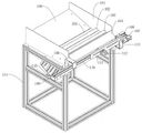
fig. 1 is a schematic structural view of an automatic sequencing and feeding device with a pier head pressing plate of the present invention;
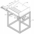
fig. 2 is a schematic structural view of the synchronous belt of the automatic sequencing feeding device with a pier nose pressing plate of the present invention;
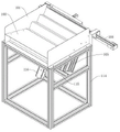
fig. 3 is a schematic structural view of the jacking plate of the automatic sequencing feeding device with the pier head pressing plate of the present invention;
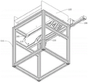
fig. 4 is a schematic view of the bottom structure of the automatic sequencing and feeding device with the pier nose pressing plate of the present invention;
fig. 5 is a flow chart of a method for using the automatic sequencing feeding device with a pier nose pressing plate of the present invention.
In the figure: 100. a first guide plate; 101. a side plate; 102. a first "V" -shaped plate; 103. a second "V" -shaped plate; 104. a second guide plate; 105. a jacking plate; 106. a first mounting bracket; 107. a drive motor; 108. a synchronous belt; 109. a synchronizing wheel; 110. a mating frame; 111. a baffle plate; 112. arranging an air cylinder; 113. a second mounting bracket; 114. an equipment frame; 115. installing a cross bar; 116. and (5) jacking the cylinder.
Detailed Description
The technical solutions in the embodiments of the present invention will be clearly and completely described below with reference to the drawings in the embodiments of the present invention, and it is obvious that the described embodiments are only some embodiments of the present invention, not all embodiments; based on the embodiments in the present invention, all other embodiments obtained by a person skilled in the art without creative work belong to the protection scope of the present invention.
First embodiment, given by fig. 1, fig. 2 and fig. 3, the utility model relates to an automatic sequencing feeding device with pier nose pressing plate, which comprises a device frame 114, the top of the device frame 114 is fixedly connected with a first guide plate 100, a first V-shaped plate 102, a second V-shaped plate 103 and a second guide plate 104, the first guide plate 100, the first V-shaped plate 102, the second V-shaped plate 103 and the second guide plate 104 are sequentially sequenced from left to right and jacking gaps are arranged between every two plates, the inner cavity of the jacking gap is slidably connected with a jacking plate 105, the height of the jacking plate must be larger than 3-4 times of the maximum diameter of a product, the jacking plate 105 can move up and down in the inner cavity of the jacking gap, thereby realizing the transmission of parts, the bottom of the jacking plate 105 is fixedly connected with a jacking cylinder 116, the jacking cylinder 116 can drive the jacking plate 105 to move up and down, the right side of the device frame 114 is provided with a matching frame 110, an inner cavity of the matching frame 110 is connected with two groups of bilaterally symmetrical synchronizing wheels 109 through a rotating shaft, the outer walls of the two groups of synchronizing wheels 109 are sleeved with synchronous belts 108, the length of the synchronous belts 108 is 2-3 times longer than that of a product, the synchronous belts 108 can be driven to translate through the synchronous wheels 109, so that the sorting and transmission of parts are realized, the back sides of the two synchronous wheels 109 at the rear side are fixedly connected with driving motors 107, the driving motors 107 can drive the two synchronous wheels 109 to rotate, so as to drive the synchronous belts 108 to translate, the middle part at the right side of the matching frame 110 is fixedly connected with a sorting cylinder 112, the sorting cylinder 112 can drive the matching frame 110 to vibrate, so that the smaller end parts of the parts are downward under the action of vibration force and gravitational pull, so as to perform the sorting of the parts, the parts are lifted through a lifting cylinder 116, so as to drive the lifting plate 105 to lift up, the parts at the top of the jacking plate 105 fall into the top of the first V-shaped plate 102 along with ascending, then the jacking cylinder 116 descends to drive the jacking plate 105 to descend to the original position, at the moment, the parts at the top of the first V-shaped plate 102 enter the top of the jacking plate 105 along with the inclination angle, the jacking cylinder 116 repeats the ascending and descending steps until the parts are conveyed to the second guide plate 104, the parts enter the synchronous belt 108 along with the inclination angle, the two driving motors 107 respectively drive the two synchronous wheels 109 to rotate, the synchronous wheels 109 drive the connected synchronous belt 108 to move forwards, the parts at the top of the synchronous belt 108 also move forwards along with the parts, at the moment, the arranging cylinder 112 drives the matching frame 110 to vibrate, the synchronous belt 108 installed inside the matching frame 110 also vibrates along with the parts, and the smaller end parts are arranged downwards under the action of the vibration force and the gravity force, so that the parts are arranged, thereby the parts can be arranged orderly from the length of bolt-shaped parts, the cylinder-shaped parts and the cylinder-shaped parts with different sizes and the head belt can be arranged disorderly, the compatibility of products is stronger, and the sound is smaller.
In the second embodiment, as shown in fig. 4, side plates 101 are arranged on the front and back sides of the first guide plate 100, the first V-shaped plate 102, the second V-shaped plate 103 and the second guide plate 104, the bottoms of the two side plates 101 are fixedly connected to the top of the equipment frame 114, and the two side plates 101 play a role in shielding to prevent parts from being separated from the equipment during transportation.
In the third embodiment, as shown in fig. 3, the middle of the equipment frame 114 is fixedly connected with a mounting cross bar 115, the jacking cylinder 116 is fixedly connected to the bottom midpoint of the mounting cross bar 115, and the mounting cross bar 115 is used for fixing the jacking cylinder 116.
In a fourth embodiment, as shown in fig. 2, the front end and the rear end of the right side of the equipment frame 114 are both fixedly connected with the first mounting brackets 106, both the first mounting brackets 106 are fixedly connected with the matching frame 110, and the first mounting brackets 106 are used for fixing the matching frame 110.
In the fifth embodiment, as shown in fig. 1, a second mounting frame 113 is fixedly connected to an outer wall of the rear side of the matching frame 110, the two driving motors 107 are connected to outer walls of left and right sides of the second mounting frame 113, and the second mounting frame 113 is used for fixedly mounting the two driving motors 107.
In the sixth embodiment, as shown in fig. 1, a baffle 111 is fixedly connected to the right side of the matching frame 110, the sorting cylinder 112 is located at the right midpoint of the baffle 111, and the baffle 111 is used to play a role of blocking when a part falls into the top of the timing belt 108 from the second guide plate 104, so as to prevent the part from falling out of the timing belt 108.
In the seventh embodiment, as shown in fig. 3, the first guide plate 100 is disposed obliquely, and the first V-shaped plate 102, the second V-shaped plate 103 and the second guide plate 104 are distributed in a stepwise manner from bottom to top, so that the transfer and transportation of the parts can be completed.
The working principle is as follows: the practical principle of the device comprises the following steps:
s1: part transportation: dumping parts needing to be loaded onto the first guide plate 100, wherein the top surface of the jacking plate 105 is flush with the top surfaces of the first guide plate 100, the first V-shaped plate 102 and the second V-shaped plate 103, the parts fall onto the top surface of the jacking plate 105 along the first guide plate 100, the jacking cylinder 116 rises to drive the jacking plate 105 to rise, the parts at the top of the jacking plate 105 fall onto the top of the first V-shaped plate 102 along with rising, then the jacking cylinder 116 descends to drive the jacking plate 105 to descend to the original position, at the moment, the parts at the top of the first V-shaped plate 102 enter the top of the jacking plate 105 along with the inclination angle, and the jacking cylinder 116 repeats the rising and descending steps until the parts are transported to the second guide plate 104 and enter the synchronous belt 108 along with the inclination angle;
s2: arranging parts: after the parts enter the top of the synchronous belt 108, the two driving motors 107 respectively drive the two synchronous wheels 109 to rotate, the synchronous wheels 109 drive the connected synchronous belt 108 to move forwards, the parts at the top of the synchronous belt 108 also move forwards, the arranging cylinder 112 drives the matching frame 110 to vibrate at the moment, the synchronous belt 108 arranged in the matching frame 110 also vibrates, and the smaller end part of the parts is downward under the action of the vibration force and the gravity, so that the arrangement and arrangement of the parts are carried out;
s3: blanking parts: along with the completion of parts arrangement, hold-in range 108 continuously forwards, and the part contacts two synchronizing wheel 109 of hold-in range 108's tip, rolls forward under the power drive of synchronizing wheel 109 pivoted, accomplishes the unloading.
Through the method, in the part transportation process, manual work is not needed to arrange parts in an up-and-down sequence, so that the manual labor force is reduced, when the parts are conveyed, a certain amount of parts are conveyed through the up-and-down movement of the jacking plate 105, the problem that the conveying of the synchronous belt 108 is blocked due to excessive conveying of the parts can be avoided, the whole equipment is simple in structure, lower in manufacturing cost, smaller in occupied area and more convenient to operate, and the synchronous belt conveying device is suitable for transportation and use of bolt-shaped parts, cylindrical parts and cylindrical parts with pressing plates.
It is noted that, herein, relational terms such as first and second, and the like may be used solely to distinguish one entity or action from another entity or action without necessarily requiring or implying any actual such relationship or order between such entities or actions. Also, the terms "comprises," "comprising," or any other variation thereof, are intended to cover a non-exclusive inclusion, such that a process, method, article, or apparatus that comprises a list of elements does not include only those elements but may include other elements not expressly listed or inherent to such process, method, article, or apparatus.
Although embodiments of the present invention have been shown and described, it will be appreciated by those skilled in the art that changes, modifications, substitutions and alterations can be made in these embodiments without departing from the principles and spirit of the invention, the scope of which is defined in the appended claims and their equivalents.
Claims (7)
1. The utility model provides a take automatic sequencing charging apparatus of pier nose clamp plate, includes equipment frame (114), its characterized in that: the top of equipment frame (114) is provided with first deflector (100), first "V" shaped plate (102), second "V" shaped plate (103) and second deflector (104), first deflector (100), first "V" shaped plate (102), second "V" shaped plate (103) and second deflector (104) are arranged in proper order and are provided with the jacking space between two liang from a left side to the right side, jacking space inner chamber is provided with jacking board (105), jacking board (105) bottom is provided with jacking cylinder (116), equipment frame (114) right side is provided with cooperation frame (110), cooperation frame (110) inner chamber is provided with two sets of bilateral symmetry's synchronizing wheel (109), and the outer wall of two sets of synchronizing wheel (109) is provided with hold-in range (108), and two synchronizing wheel (109) dorsal parts of rear side all are provided with driving motor (107), cooperation frame (110) right side middle part is provided with arrangement cylinder (112).
2. The automatic sequencing and feeding equipment with the pier head pressing plates according to claim 1, characterized in that: the front side and the rear side of the first guide plate (100), the first V-shaped plate (102), the second V-shaped plate (103) and the second guide plate (104) are provided with side plates (101), and the bottoms of the two side plates (101) are connected to the top of the equipment frame (114).
3. The automatic sequencing and feeding device with the pier head pressing plate according to claim 2, characterized in that: the middle part of the equipment frame (114) is provided with an installation cross rod (115), and the jacking cylinder (116) is connected to the bottom midpoint of the installation cross rod (115).
4. The automatic sequencing and feeding equipment with the pier head pressing plates according to claim 1, characterized in that: the front end and the rear end of the right side of the equipment frame (114) are respectively provided with a first mounting rack (106), and the two first mounting racks (106) are connected with the matching frame (110).
5. The automatic sequencing and feeding equipment with the pier head pressing plate according to claim 4, characterized in that: the outer wall of the rear side of the matching frame (110) is provided with a second mounting frame (113), and two driving motors (107) are connected to the outer wall of the left side and the right side of the second mounting frame (113).
6. The automatic sequencing and feeding device with the pier head pressing plate according to claim 5, wherein: the right side of the matching frame (110) is provided with a baffle (111), and the tidying cylinder (112) is located at the right midpoint of the baffle (111).
7. The automatic sequencing and feeding equipment with the pier head pressing plate according to claim 1, characterized in that: the first guide plate (100) is obliquely arranged, and the first V-shaped plate (102), the second V-shaped plate (103) and the second guide plate (104) are distributed in a stepped mode from low to high.
Priority Applications (1)
| Application Number | Priority Date | Filing Date | Title |
|---|---|---|---|
| CN202221753341.2U CN217946713U (en) | 2022-07-08 | 2022-07-08 | Take automatic sequencing charging equipment of pier nose clamp plate |
Applications Claiming Priority (1)
| Application Number | Priority Date | Filing Date | Title |
|---|---|---|---|
| CN202221753341.2U CN217946713U (en) | 2022-07-08 | 2022-07-08 | Take automatic sequencing charging equipment of pier nose clamp plate |
Publications (1)
| Publication Number | Publication Date |
|---|---|
| CN217946713U true CN217946713U (en) | 2022-12-02 |
Family
ID=84220081
Family Applications (1)
| Application Number | Title | Priority Date | Filing Date |
|---|---|---|---|
| CN202221753341.2U Active CN217946713U (en) | 2022-07-08 | 2022-07-08 | Take automatic sequencing charging equipment of pier nose clamp plate |
Country Status (1)
| Country | Link |
|---|---|
| CN (1) | CN217946713U (en) |
-
2022
- 2022-07-08 CN CN202221753341.2U patent/CN217946713U/en active Active
Similar Documents
| Publication | Publication Date | Title |
|---|---|---|
| CN217946713U (en) | Take automatic sequencing charging equipment of pier nose clamp plate | |
| CN208531462U (en) | A kind of Intelligent double-layer tray carriage | |
| CN114348596A (en) | Automatic welding, assembling and packaging machine | |
| CN210854328U (en) | Paper holder feeding device | |
| CN210854383U (en) | Tray conveying device | |
| CN108482955A (en) | A kind of Intelligent double-layer tray carriage | |
| CN105984603A (en) | Settling machine for multiple bar-shaped materials | |
| CN112390515A (en) | Automatic feed supplement system of glass softening furnace | |
| CN115196290A (en) | Automatic sequencing feeding device with pier head pressing plates and using method thereof | |
| CN213111380U (en) | Automatic change feeding mechanism for feedway | |
| CN113306785B (en) | Full-automatic feeding, weighing and packaging integrated machine for ribbon production | |
| CN216612881U (en) | Elbow automatic feeding machine | |
| CN214139139U (en) | Bucket type vertical lifting and feeding mechanism | |
| CN213111453U (en) | Automatic change stacking mechanism for feeder | |
| CN216360222U (en) | Elbow automatic feeding device | |
| CN210214006U (en) | Automatic material distributing mechanism | |
| CN112850029A (en) | Automatic elbow feeding device and feeding method | |
| CN212558351U (en) | High-efficiency low-cost automatic feeding system | |
| CN215709782U (en) | Flitch conveying mechanism of three-dimensional curing oven | |
| CN113666090B (en) | USB line box feeding mechanism and operation method thereof | |
| CN212558352U (en) | Feeding mechanism for automatic feeding machine | |
| CN220635252U (en) | Bamboo article sieving mechanism | |
| CN216968767U (en) | Discharge structure for metal piece pressing production | |
| CN219949759U (en) | Automatic feeding machine | |
| CN219382963U (en) | Cylinder ration reason material device |
Legal Events
| Date | Code | Title | Description |
|---|---|---|---|
| GR01 | Patent grant | ||
| GR01 | Patent grant |