CN217757783U - Carding device for spinning - Google Patents
Carding device for spinning Download PDFInfo
- Publication number
- CN217757783U CN217757783U CN202220796347.1U CN202220796347U CN217757783U CN 217757783 U CN217757783 U CN 217757783U CN 202220796347 U CN202220796347 U CN 202220796347U CN 217757783 U CN217757783 U CN 217757783U
- Authority
- CN
- China
- Prior art keywords
- spinning
- rack
- carding device
- collection box
- dust collection
- Prior art date
- Legal status (The legal status is an assumption and is not a legal conclusion. Google has not performed a legal analysis and makes no representation as to the accuracy of the status listed.)
- Active
Links
Images



Landscapes
- Preliminary Treatment Of Fibers (AREA)
Abstract
The utility model relates to a spinning field specifically is a carding device for spinning, including base and collecting box, the both sides of base all are provided with the support frame, and the top of support frame is provided with the axis of rotation, the rear end of axis of rotation is provided with the driving roller, and the externally mounted of driving roller has the rack, the externally mounted of rack has the conveyer belt, and the both sides of conveyer belt all install the fixed plate, the top of fixed plate is provided with the dead lever, and the externally mounted of dead lever has the destatic drum. This carding unit for spinning sets up the axis of rotation, makes the driving roller drive the rack and rotates to play the effect of carrying to the spinning, set up and remove the static cylinder, through removing the roll of static cylinder on the spinning, reach the purpose of removing static, make things convenient for the spinning to place, set up the broach, start the pneumatic cylinder, make the pneumatic cylinder go up and down to drive the broach and carry out the pre-carding to the surface of spinning downwards, the broach effect on rethread right side carries out thoroughly combing, thereby has realized combing to the spinning.
Description
Technical Field
The utility model relates to a spinning technical field specifically is a carding device is used in spinning.
Background
Spinning is a very ancient activity, since prehistoric times, which is understood by man to spin long yarns from shorter fibres and then to weave them into cloth, so-called spinning, which involves the cohesion of animal or vegetable fibres by twisting into a continuous infinitely extending yarn suitable for a weaving action, and therefore requires combing devices.
The carding device on the market at present is not convenient for go the static carding to the spinning, generally combs the hair to the spinning, and most accomplish by the manual work to the process of combing easily produces static, makes the spinning become more in disorder, and the quality reduces, and carding method inefficiency, to above-mentioned circumstances, carries out technical innovation on the basis of current carding device, for this we propose a carding device for spinning.
In view of the above problems, there is an urgent need for innovative design based on the original carding device.
SUMMERY OF THE UTILITY MODEL
Not enough to prior art, the utility model provides a carding device is used in spinning possesses and is convenient for go static carding characteristics to the spinning, has solved and has not been convenient for go the problem of static carding to the spinning.
In order to achieve the above object, the utility model provides a following technical scheme: the utility model provides a carding device for spinning, includes base and collecting box, the both sides of base all are provided with the support frame, and the top of support frame is provided with the axis of rotation, the rear end of axis of rotation is provided with the driving roller, and the externally mounted of driving roller has the rack, the externally mounted of rack has the conveyer belt, and the both sides of conveyer belt all install the fixed plate, the top of fixed plate is provided with the dead lever, and the externally mounted of dead lever has the static cylinder of going, the top of base is provided with the support, and the roof is installed on the top of support.
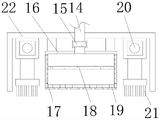
The inside of collecting box is provided with the air exhauster, and the bottom of air exhauster is provided with the connecting pipe, the externally mounted valve of connecting pipe, and the bottom of connecting pipe is provided with the suction box, the otter board is all installed to the both sides of suction box, and the internally mounted of otter board has the adsorption plate, the bottom of suction box is provided with the dust absorption head, and the both sides of suction box all are provided with the pneumatic cylinder, the bottom of pneumatic cylinder is provided with the broach, and the externally mounted of broach has the dust frame.
Furthermore, the support frame and the rotating shaft are perpendicular to each other, and the rotating shaft and the driving roller are rotatably connected.
Furthermore, the transmission roller is meshed with the rack, and the rack is tightly attached to the conveyor belt.
Furthermore, the fixed plate and the fixed rod are arranged vertically, and the fixed rod and the static removing roller are connected in a nested manner.
Furthermore, the collecting box is connected with the exhaust fan in a nested manner, and the exhaust fan is fixedly connected with the connecting pipe.
Furthermore, the second dust collection box and the screen plate are integrally arranged, and the dust collection box and the adsorption plate are connected in a nested manner.
Furthermore, the pneumatic cylinder coincides with the axis of broach mutually, and is fixed connection between pneumatic cylinder and the dust removal frame.
Compared with the prior art, the technical scheme of the application has the following beneficial effects:
1. this carding unit for spinning sets up the axis of rotation, makes the driving roller drive the rack and rotates to play the effect of carrying to the spinning, set up and remove the static cylinder, through removing the roll of static cylinder on the spinning, reach the purpose of removing static, make things convenient for the spinning to place, set up the broach, start the pneumatic cylinder, make the pneumatic cylinder go up and down to drive the broach and carry out the pre-carding to the surface of spinning downwards, the broach effect on rethread right side carries out thoroughly combing, thereby has realized combing to the spinning.
2. This carding unit is used in spinning sets up air exhauster and valve, makes the air exhauster take out the air of suction box inside from to make the suction box be in the negative pressure state, fly the wadding will carry out comprehensive absorption through dust absorption head and otter board and enter the suction box in, set up the connecting pipe, collect the flying wadding in the suction box, set up the adsorption plate, filter and block flying wadding, thereby realize being convenient for to the collection of flying wadding.
Drawings
Fig. 1 is a schematic view of the front cross-sectional structure of the present invention;
FIG. 2 is a front view of the dust-removing frame of the present invention;
FIG. 3 is a schematic front view of the present invention;
FIG. 4 is a schematic perspective view of the present invention;
fig. 5 is an enlarged view of a portion a in fig. 1 according to the present invention.
In the figure: 1. a base; 2. a support frame; 3. a rotating shaft; 4. a driving roller; 5. a rack; 6. a conveyor belt; 7. a fixing plate; 8. a fixing rod; 9. a destaticizing drum; 10. a support; 11. a top plate; 12. a collection box; 13. an exhaust fan; 14. a connecting pipe; 15. a valve; 16. a dust collection box; 17. a screen plate; 18. an adsorption plate; 19. a dust collection head; 20. a hydraulic cylinder; 21. comb teeth; 22. a dust removal frame.
Detailed Description
The technical solutions in the embodiments of the present invention will be described clearly and completely with reference to the accompanying drawings in the embodiments of the present invention, and it is obvious that the described embodiments are only some embodiments of the present invention, not all embodiments. Based on the embodiments in the present invention, all other embodiments obtained by a person skilled in the art without creative work belong to the protection scope of the present invention.
Referring to fig. 1-5, the carding device for spinning in this embodiment includes a base 1 and a collecting box 12, wherein two sides of the base 1 are respectively provided with a support frame 2, a rotation shaft 3 is arranged on the top end of the support frame 2, a driving roller 4 is arranged at the rear end of the rotation shaft 3, a rack 5 is arranged outside the driving roller 4, a conveyor belt 6 is arranged outside the rack 5, fixing plates 7 are arranged on two sides of the conveyor belt 6, a fixing rod 8 is arranged on the top end of the fixing plate 7, a static removing roller 9 is arranged outside the fixing rod 8, a support 10 is arranged on the top end of the base 1, and a top plate 11 is arranged on the top end of the support 10.
An exhaust fan 13 is arranged inside the collection box 12, a connecting pipe 14 is arranged at the bottom end of the exhaust fan 13, a valve 15 is arranged outside the connecting pipe 14, a dust collection box 16 is arranged at the bottom end of the connecting pipe 14, screen plates 17 are arranged on two sides of the dust collection box 16, an adsorption plate 18 is arranged inside the screen plates 17, a dust collection head 19 is arranged at the bottom end of the dust collection box 16, hydraulic cylinders 20 are arranged on two sides of the dust collection box 16, comb teeth 21 are arranged at the bottom end of the hydraulic cylinders 20, and a dust collection frame 22 is arranged outside the comb teeth 21.
Referring to fig. 1, 3 and 4, in the present embodiment, the supporting frame 2 and the rotating shaft 3 are perpendicular to each other, and the rotating shaft 3 is rotatably connected to the driving roller 4.
It should be noted that, the external motor on one side of the supporting frame 2 is started, so that the driving roller 4 is driven to rotate through the rotating shaft 3, and the driving roller 4 drives the rack 5 to rotate.
Referring to fig. 1, 3 and 4, in the present embodiment, the driving roller 4 is engaged with the rack 5, and the rack 5 is tightly attached to the conveyor belt 6.
It should be noted that the rack 5 rotates to drive the conveyor belt 6 to rotate, so as to convey the spun yarn.
Referring to fig. 1, 4 and 5, in the present embodiment, the fixing plate 7 and the fixing rod 8 are disposed perpendicular to each other, and the fixing rod 8 and the static removing roller 9 are connected in a nested manner.
The spun yarn passes through the static removing roller 9 on the left side, and the static removing roller 9 rolls on the spun yarn to achieve the purpose of static removing.
Referring to fig. 1, 2 and 3, in the present embodiment, the collecting box 12 is connected to the suction fan 13 in a nested manner, and the suction fan 13 is fixedly connected to the connecting pipe 14.
It should be noted that the suction fan 13 and the valve 15 are activated, so that the suction fan 13 draws air out of the interior of the suction box 16.
Referring to fig. 1, 2 and 3, in the present embodiment, the second dust box 16 and the net plate 17 are integrally disposed, and the dust box 16 and the adsorption plate 18 are connected in a nested manner.
It should be noted that the dust box 16 is under negative pressure, and the flying flocks will be sucked into the dust box 16 through the dust suction head 19 and the screen 17.
Referring to fig. 1 and 2, in the present embodiment, the central axes of the hydraulic cylinder 20 and the comb 21 are coincident, and the hydraulic cylinder 20 and the dust-removing frame 22 are fixedly connected.
It should be noted that, the comb teeth 21 are arranged, the hydraulic cylinder 20 is started, the hydraulic cylinder 20 drives the comb teeth 21 to move downwards to pre-comb the surface of the spun yarn, and then the right comb teeth 21 act to completely comb the yarn.
It can be understood that, this carding device for spinning, set up axis of rotation 3, make driving roller 4 drive rack 5 and rotate, thereby play the effect of carrying to the spinning, set up and remove electrostatic cylinder 9, through removing the roll of electrostatic cylinder 9 on the spinning, reach the purpose of removing static, it places to make things convenient for the spinning, set up broach 21, start hydraulic cylinder 20, make pneumatic cylinder 20 go up and down to drive broach 21 and carry out the pre-carding downwards to the surface of spinning, then the broach 21 effect that rethread right side carries out thorough combing, thereby realized combing the spinning, set up air exhauster 13 and valve 15, make air suction box 16 inside air pump-off of air exhauster 13, thereby make dust suction box 16 be in the negative pressure state, the flying cotton wool will carry out comprehensive absorption through dust absorption head 19 and otter board 17 and enter dust suction box 16, set up connecting pipe 14, collect the flying cotton wool in the dust suction box 16, set up adsorption plate 18, filter and block the flying cotton wool, thereby realize being convenient for the collection of flying cotton wool.
The working principle of the above embodiment is as follows:
when the carding device needs to be used, a user lays a spun yarn on the conveyor belt 6 in a flat manner, then starts an external motor on one side of the support frame 2, so that the drive roller 4 is driven to rotate through the rotating shaft 3, the drive roller 4 is meshed with the rack 5, the drive roller 4 drives the rack 5 to rotate, the rack 5 is driven to rotate to drive the conveyor belt 6 to rotate, and the spun yarn is conveyed;
then, the in-process of combing the spinning can produce the flying cotton fibre, then start air exhauster 13 and valve 15, make air exhauster 13 take out the inside air of suction box 16 and separate, thereby make suction box 16 be in the negative pressure state, the flying cotton fibre will carry out comprehensive absorption through dust absorption head 19 and otter board 17 into suction box 16 this moment, the flying cotton fibre in with suction box 16 is collected through connecting pipe 14, filter and block the flying cotton fibre through adsorption plate 18 simultaneously, thereby make flying cotton fibre and dust gathering inside suction box 16, thereby the realization is convenient for the collection to the flying cotton fibre.
It should be noted that, in this document, relational terms such as first and second, and the like are used solely to distinguish one entity or action from another entity or action without necessarily requiring or implying any actual such relationship or order between such entities or actions. Also, the terms "comprises," "comprising," or any other variation thereof, are intended to cover a non-exclusive inclusion, such that a process, method, article, or apparatus that comprises a list of elements does not include only those elements but may include other elements not expressly listed or inherent to such process, method, article, or apparatus. Without further limitation, an element defined by the phrases "comprising a component of' 8230; \8230;" does not exclude the presence of additional identical elements in the process, method, article, or apparatus that comprises the element.
Although embodiments of the present invention have been shown and described, it will be appreciated by those skilled in the art that changes, modifications, substitutions and alterations can be made in these embodiments without departing from the principles and spirit of the invention, the scope of which is defined in the appended claims and their equivalents.
Claims (7)
1. A carding device for spinning comprises a base (1) and a collecting box (12), and is characterized in that: the automatic cleaning device is characterized in that supporting frames (2) are arranged on two sides of the base (1), a rotating shaft (3) is arranged at the top end of each supporting frame (2), a transmission roller (4) is arranged at the rear end of each rotating shaft (3), a rack (5) is arranged outside each transmission roller (4), a conveyor belt (6) is arranged outside each rack (5), fixing plates (7) are arranged on two sides of each conveyor belt (6), a fixing rod (8) is arranged at the top end of each fixing plate (7), a static removing roller (9) is arranged outside each fixing rod (8), a support (10) is arranged at the top end of the base (1), and a top plate (11) is arranged at the top end of each support (10);
the inside of collecting box (12) is provided with air exhauster (13), and the bottom of air exhauster (13) is provided with connecting pipe (14), externally mounted valve (15) of connecting pipe (14), and the bottom of connecting pipe (14) is provided with dust collection box (16), otter board (17) are all installed to the both sides of dust collection box (16), and the internally mounted of otter board (17) has adsorption plate (18), the bottom of dust collection box (16) is provided with dust absorption head (19), and the both sides of dust collection box (16) all are provided with pneumatic cylinder (20), the bottom of pneumatic cylinder (20) is provided with broach (21), and the externally mounted of broach (21) has dust removal frame (22).
2. A carding device for spinning according to claim 1, characterized in that: the supporting frame (2) and the rotating shaft (3) are perpendicular to each other, and the rotating shaft (3) and the transmission roller (4) are rotatably connected.
3. A carding device for spinning according to claim 1, characterized in that: the transmission roller (4) is meshed with the rack (5), and the rack (5) is tightly attached to the conveyor belt (6).
4. A carding device for spinning according to claim 1, wherein: the fixing plate (7) and the fixing rod (8) are perpendicular to each other, and the fixing rod (8) and the static removing roller (9) are connected in a nested manner.
5. A carding device for spinning according to claim 1, wherein: the collection box (12) is connected with the exhaust fan (13) in a nested manner, and the exhaust fan (13) is fixedly connected with the connecting pipe (14).
6. A carding device for spinning according to claim 1, characterized in that: the dust collection box (16) and the screen plate (17) are integrally arranged, and the dust collection box (16) and the adsorption plate (18) are connected in a nested manner.
7. A carding device for spinning according to claim 1, characterized in that: the hydraulic cylinder (20) is coincided with the central axis of the comb teeth (21), and the hydraulic cylinder (20) is fixedly connected with the dust removal frame (22).
Priority Applications (1)
| Application Number | Priority Date | Filing Date | Title |
|---|---|---|---|
| CN202220796347.1U CN217757783U (en) | 2022-04-07 | 2022-04-07 | Carding device for spinning |
Applications Claiming Priority (1)
| Application Number | Priority Date | Filing Date | Title |
|---|---|---|---|
| CN202220796347.1U CN217757783U (en) | 2022-04-07 | 2022-04-07 | Carding device for spinning |
Publications (1)
| Publication Number | Publication Date |
|---|---|
| CN217757783U true CN217757783U (en) | 2022-11-08 |
Family
ID=83882052
Family Applications (1)
| Application Number | Title | Priority Date | Filing Date |
|---|---|---|---|
| CN202220796347.1U Active CN217757783U (en) | 2022-04-07 | 2022-04-07 | Carding device for spinning |
Country Status (1)
| Country | Link |
|---|---|
| CN (1) | CN217757783U (en) |
-
2022
- 2022-04-07 CN CN202220796347.1U patent/CN217757783U/en active Active
Similar Documents
| Publication | Publication Date | Title |
|---|---|---|
| CN110219158B (en) | Carding machine with dust removal function | |
| CN210368097U (en) | Carding device for spinning thread layer | |
| CN215785136U (en) | Surface cleaning device is processed in production of regeneration weaving cotton yarn | |
| CN107043964A (en) | A kind of efficient impurity elimination dedusting spinning carding machine | |
| CN110552098A (en) | Surface treatment system for production and processing of regenerated textile cotton yarns | |
| CN212247587U (en) | A unhairing wool-absorbing device for weaving printing and dyeing | |
| CN106894118A (en) | A kind of too many levels spinning dust removal machine | |
| CN214400847U (en) | Rotor spinning machine with dust removal effect | |
| CN217757783U (en) | Carding device for spinning | |
| CN219378088U (en) | Cotton textile carding device | |
| CN216711040U (en) | Conveying mechanism with hair removing function for textile processing fabric | |
| CN216074133U (en) | Cotton yarn weaving carding equipment | |
| CN214300526U (en) | High-efficiency roving frame lint cleaning device | |
| CN210506922U (en) | Textile fabric and wool cleaning equipment with dust collection function | |
| CN210712287U (en) | Cleaning device of raising machine | |
| CN220555729U (en) | Impurity removal carding machine device for cotton yarn processing | |
| CN218175241U (en) | Drawing device for spinning | |
| CN221778159U (en) | Cotton textile carding device | |
| CN214400854U (en) | Cleaning device for flying wadding on spinning frame | |
| CN221544851U (en) | Carding box with cotton pressing mechanism | |
| CN215713584U (en) | Spunlace is comb and parallel cotton fibers prior to spinning device for non-woven fabrics | |
| CN216324108U (en) | Clean mechanism of weaving equipment | |
| CN221460626U (en) | Dust remover of semi-worsted carding machine | |
| CN216738716U (en) | Frequency conversion weaving equipment | |
| CN211897523U (en) | Fluff removing device for scarf textile processing |
Legal Events
| Date | Code | Title | Description |
|---|---|---|---|
| GR01 | Patent grant | ||
| GR01 | Patent grant |