CN217752227U - Discharging dust collector for granulator - Google Patents
Discharging dust collector for granulator Download PDFInfo
- Publication number
- CN217752227U CN217752227U CN202222108702.4U CN202222108702U CN217752227U CN 217752227 U CN217752227 U CN 217752227U CN 202222108702 U CN202222108702 U CN 202222108702U CN 217752227 U CN217752227 U CN 217752227U
- Authority
- CN
- China
- Prior art keywords
- shell
- fixed mounting
- guide wheel
- granulator
- bin outlet
- Prior art date
- Legal status (The legal status is an assumption and is not a legal conclusion. Google has not performed a legal analysis and makes no representation as to the accuracy of the status listed.)
- Active
Links
Images



Classifications
-
- Y—GENERAL TAGGING OF NEW TECHNOLOGICAL DEVELOPMENTS; GENERAL TAGGING OF CROSS-SECTIONAL TECHNOLOGIES SPANNING OVER SEVERAL SECTIONS OF THE IPC; TECHNICAL SUBJECTS COVERED BY FORMER USPC CROSS-REFERENCE ART COLLECTIONS [XRACs] AND DIGESTS
- Y02—TECHNOLOGIES OR APPLICATIONS FOR MITIGATION OR ADAPTATION AGAINST CLIMATE CHANGE
- Y02W—CLIMATE CHANGE MITIGATION TECHNOLOGIES RELATED TO WASTEWATER TREATMENT OR WASTE MANAGEMENT
- Y02W30/00—Technologies for solid waste management
- Y02W30/50—Reuse, recycling or recovery technologies
- Y02W30/62—Plastics recycling; Rubber recycling
Landscapes
- Processing And Handling Of Plastics And Other Materials For Molding In General (AREA)
Abstract
The utility model belongs to the technical field of the granulator, and a row's material dust catcher is used to granulator is disclosed, which comprises an outer shell, the right-hand member fixed mounting of shell bottom has first bin outlet, the left end fixed mounting of shell bottom has the second bin outlet, the right side fixed mounting of shell has the dust catcher, the bottom on shell right side is provided with first collecting box, the top of shell and the bottom that is located the second bin outlet are provided with the second collecting box. The utility model discloses a be provided with guide wheel, pin and screening board etc. and reached the purpose of granule screening, when row's material is expected to needs, will start the dust catcher, the inside of dust catcher through the shell row the material to the granulator this moment, the granule will be through the top of guide wheel, great granule will pass through the suction of dust catcher, from falling into the top of screening board between the three pin, the filter screen of rethread screening board top left end sieves the granule once more, makes it reach the effect of granule screening.
Description
Technical Field
The utility model belongs to the technical field of the granulator, specifically a granulator is with arranging material dust catcher.
Background
The granulator is an auxiliary machine of a molding mechanical plastic granulator set which can manufacture materials into specific shapes, and mainly comprises a pay-off device, a straightening device, a preheating device, a cooling device, a traction device, a meter counter, a spark tester and a take-up device. The extruder set is used in different applications and has different auxiliary equipment for selection. Such as a cutter, a blow dryer, a printer, etc. The extruder is an exhaust type extruder and is used for re-mixing, heating and melting crushed plastic which is crushed, cleaned and dried by the extruder, and then extruding and pelletizing the plastic. Because the sources of waste plastic products are complex, the composition models of the mixture are various, and the volatile matters, the moisture and other components in the material are more, the exhaust type extruder is more suitable. The waste plastic is mixed and melted by an exhaust extruder, and the shape of the material is special, so that spiral forced feeding is adopted; a filter screen is added in front of the machine barrel, and the molten material is extruded by a perforated plate and then cut into particles. And (4) waste recycling, namely extruding strips, cooling and shaping through a water tank, and then cutting into granules for collection.
Granulator among the prior art arranges the material, use directly to arrange the material or stir out through the auger to the plastic granules after production is accomplished usually, when plastic granules is more, directly arrange the material and will unable discharge completely, lead to arranging material pipe blockage, need clear up it through the manual work, can't sieve plastic granules when arranging the material through the auger, because plastics are when the shaping is cut grain, the size that can't guarantee the granule is unanimous, need sieve plastic granules, the labour has been increased, and plastic granules is more to be difficult to the screening.
SUMMERY OF THE UTILITY MODEL
For solving the problem that proposes among the above-mentioned background art, the utility model provides a granulator is with arranging material dust catcher has the granule screening, is convenient for clear advantage.
In order to achieve the above object, the utility model provides a following technical scheme: the utility model provides a granulator is with arranging material dust catcher, includes the shell, the right-hand member fixed mounting of shell bottom has first bin outlet, the left end fixed mounting of shell bottom has the second bin outlet, the right side fixed mounting of shell has the dust catcher, the bottom on shell right side is provided with first collecting box, the top of shell and the bottom that is located the second bin outlet are provided with the second collecting box, the top fixed mounting of the inside left end of shell has the guide board, the left end equidistance movable mounting of the inside bottom of shell has the guide wheel, the right-hand member equidistance fixed mounting of the inside bottom of shell has three pin, the right-hand member fixed mounting at first bin outlet middle part has the screening board, the fixed welding in left side of shell has the butt joint, the front fixed mounting of guide wheel has the knob.
Among the above-mentioned technical scheme, it is preferred, there is the second stopper around the inside left end of shell respectively fixed mounting, the inboard activity joint of second stopper has the baffle, there is first stopper around the inside right-hand member of shell respectively fixed mounting, the inboard activity joint of first stopper has the filter plate.
Among the above-mentioned technical scheme, preferred, the inside bottom of shell is low right height on a left side, the shell is located the inside top of second bin outlet, the pin is located the inside top of first bin outlet.
Among the above-mentioned technical scheme, it is preferred, the lower extreme of guide board is the arc, the lower extreme of guide board is located the inside front and back of shell, the bottom of guide board is located the top of guide wheel.
Among the above-mentioned technical scheme, preferred, the guide wheel is the cross, the knob runs through in the front of shell, the guide wheel is located the inside top of second bin outlet.
Among the above-mentioned technical scheme, preferably, the left end at screening board top has seted up the circular port, the screening board is high on the left side low on the right side, the bottom of screening board right-hand member is located the top of first collecting box.
Among the above-mentioned technical scheme, preferred, first stopper is thirty degrees slopes, the lower extreme of filter plate is thirty degrees slopes, the left lower extreme of filter plate is located the right side of pin.
Compared with the prior art, the beneficial effects of the utility model are as follows:
1. the utility model discloses a be provided with the guide wheel, the pin has reached the mesh of granule screening with screening board etc, when row's material is arranged to needs, will start the dust catcher, the inside that the dust catcher passes through the shell at this moment arranges the material to the granulator, the inside granule of granulator will be inhaled the inside of shell, the granule will be through the top of guide wheel, sieve the granule through the guide wheel, the granule that accords with required size will fall into the inside of second collecting box through the second bin outlet, the granule that is not conform to size will remove at the inside looks right-hand member of shell through the rotatory guide of guide wheel, great granule will pass through the suction of dust catcher, from falling into the top of screening board between the three pin, the rethread screens the granule again of screening board top left end, make it reach the effect that the granule was sieved.
2. The utility model discloses a be provided with baffle, second stopper and first stopper etc. and reached the clear purpose of being convenient for, after long-time work, through carrying out the baffle to the inside left end of shell closed, upwards pulling out the filter plate, clear up the surface of filter plate for the dust catcher is more complete to the row of granulator material, and it is better to arrange the material effect, makes it reach the clear effect of being convenient for.
Drawings
FIG. 1 is a schematic view of the overall appearance of the structure of the present invention;
FIG. 2 is a schematic sectional view of the front side of the structure of the present invention;
FIG. 3 is a schematic view of the inside of the structure of the present invention;
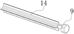
FIG. 4 is an external view of the structure guiding wheel of the present invention;
fig. 5 is a schematic diagram of the filter plate of the present invention.
In the figure: 1. a housing; 2. a first discharge port; 3. filtering the plate; 4. a vacuum cleaner; 5. a screening plate; 6. a first collection tank; 7. a second collection tank; 8. a second discharge opening; 9. a rotation knob; 10. a butt joint port; 11. a baffle plate; 12. a stop lever; 13. a guide plate; 14. a guide wheel; 15. a first stopper; 16. and a second limiting block.
Detailed Description
The technical solutions in the embodiments of the present invention will be described clearly and completely with reference to the accompanying drawings in the embodiments of the present invention, and it is obvious that the described embodiments are only some embodiments of the present invention, not all embodiments. Based on the embodiments in the present invention, all other embodiments obtained by a person skilled in the art without creative work belong to the protection scope of the present invention.
As shown in fig. 1 to 5, the utility model provides a discharging dust collector for granulator, including shell 1, the right-hand member fixed mounting of shell 1 bottom has first bin outlet 2, the left end fixed mounting of shell 1 bottom has second bin outlet 8, the right side fixed mounting of shell 1 has dust catcher 4, the bottom on shell 1 right side is provided with first collecting box 6, the top of shell 1 and the bottom that is located second bin outlet 8 are provided with second collecting box 7, the top fixed mounting of shell 1 inside left end has guide plate 13, the left end equidistance movable mounting of shell 1 inside bottom has guide wheel 14, the right-hand member equidistance fixed mounting of shell 1 inside bottom has three pin 12, the right-hand member fixed mounting in the middle part of first bin outlet 2 has sieve plate 5, the left side fixed welding of shell 1 has butt joint 10, the front fixed mounting of guide wheel 14 has knob 9;
through will be to interface 10 and granulator to the intercommunication, when needs are arranged the material to the granulator, pull out baffle 11 upwards, start dust catcher 4 and arrange the material to the granulator, the inside of sucking the inside plastic granules suction shell 1 of granulator through dust catcher 4, sieve plastic granules through guide wheel 14, the inside that the size that meets the requirements will fall into second collecting box 7 through second bin outlet 8 is collected, the plastic granules of size that does not conform to falls into the inside of first collecting box 6 through the right-hand member of the inside bottom of shell 1, the left side of dust catcher 4 communicates in the inside of shell 1.
As shown in fig. 2, 3 and 5, a second limiting block 16 is fixedly mounted at the front and back of the left end inside the shell 1, a baffle 11 is movably clamped at the inner side of the second limiting block 16, a first limiting block 15 is fixedly mounted at the front and back of the right end inside the shell 1, and a filter plate 3 is movably clamped at the inner side of the first limiting block 15;
the scheme is adopted: after discharging the granulator for a long time through the shell 1, more impurities will be attached to the surface of the filter plate 3, so that the working efficiency of the dust collector 4 is reduced, the surface of the filter plate 3 is cleaned up by pulling the filter plate 3 upwards at regular intervals, and the working efficiency of the dust collector 4 is increased.
As shown in fig. 1, 2 and 3, the bottom inside the outer shell 1 is lower left and higher right, the outer shell 1 is positioned at the top inside the second discharge port 8, and the stop rod 12 is positioned at the top inside the first discharge port 2;
the scheme is adopted: plastic granules inside the granulator are sucked into the shell 1 through the dust collector 4, the plastic granules are screened through the guide wheels 14, and the plastic granules are buffered and screened through the radian of the bottom of the shell 1, so that the plastic granules are better screened.
As shown in fig. 2, 3 and 4, the lower end of the guide plate 13 is arc-shaped, the lower end of the guide plate 13 is located at the front and back of the inside of the housing 1, and the bottom of the guide plate 13 is located at the top of the guide wheel 14;
adopt above-mentioned scheme: arrange the material through starting dust catcher 4 to the inside plastic granules of granulator, the suction of dust catcher 4 will be arranged the material through the bottom of guide board 13 to the inside granule of granulator, when plastics get into the inside of shell 1, at the guide through guide board 13 radians for the effect of screening plastic granules is better.
As shown in fig. 1, 2 and 4, the guiding wheel 14 is cross-shaped, the rotary knob 9 penetrates through the front surface of the housing 1, and the guiding wheel 14 is positioned at the top inside the second discharge opening 8;
adopt above-mentioned scheme: when arranging the material to the inside of granulator through starting dust catcher 4, the suction of dust catcher 4 will drive guide wheel 14 rotatory, guide plastic granules through guide wheel 14 is rotatory, through the plastic granules at guide wheel 14 top, the plastic granules that accords with the size falls into the inside of second collecting box 7 through the clearance between the guide wheel 14 and collects, the plastic granules at guide wheel 14 top more leads to guide wheel 14 to block up, clear up the plastics at guide wheel 14 top through rotatory knob 9.
As shown in fig. 2 and 3, a circular hole is formed at the left end of the top of the screening plate 5, the screening plate 5 is high at the left and low at the right, and the bottom of the right end of the screening plate 5 is positioned at the top of the first collecting box 6;
adopt above-mentioned scheme: guide the inside right-hand member of shell 1 to the bigger granule through the rotation of guide wheel 14, fall into the top of screening board 5 through the clearance between pin 12, carry out screening once more to the granule through the left end at screening board 5 top, bigger granule will fall into the inside of first collecting box 6 through the right-hand member at screening board 5 top and collect.
As shown in fig. 2 and 3, the first limit block 15 is inclined at thirty degrees, the lower end of the filter plate 3 is inclined at thirty degrees, and the lower end of the left side of the filter plate 3 is located on the right side of the stop lever 12;
the scheme is adopted: carry out long-term row material to the granulator through dust catcher 4, more impurity will be adhered to on the surface of filter plate 3, regularly upwards pulls out filter plate 3 and clears up the surface of filter plate 3 for the efficiency of dust catcher 4 work is higher.
The utility model discloses a theory of operation and use flow:
the discharge opening of the interfacing port 10 and the granulator is connected, when discharging is needed, firstly, the baffle 11 is pulled upwards, the dust collector 4 is started again, at the moment, the dust collector 4 discharges the granulator through the inside of the shell 1, particles inside the granulator can be sucked into the inside of the shell 1, the particles can pass through the top of the guide wheel 14, the particles are screened through the guide wheel 14, the particles meeting the requirements are guided to fall into the second collecting box 7 through the second discharge opening 8, when the guide wheel 14 is blocked and cannot rotate due to more plastic particles inside the shell 1, the plastic particles at the top of the guide wheel 14 are cleaned through the rotary knob 9 at the moment, the particles which do not meet the requirements are guided to move at the right end inside the shell 1 through the rotation of the guide wheel 14, meanwhile, the particles are buffered and screened through the slope in the middle of the shell 1, larger particles can pass through the suction force of the dust collector 4, the top of the screening plate 5 is screened from the left end of the three blocking rods 12, the left end of the screening plate 5 at the left end of the screening plate 5 can sieve again, the larger particles can fall into the left side of the second collecting box through the left side blocking plate 6, and the left side blocking plate 5, the blocking plate 5, and the blocking plate is discharged through the left blocking block plate discharging stopper 16, and the screen.
It should be noted that, in this document, relational terms such as first and second, and the like are used solely to distinguish one entity or action from another entity or action without necessarily requiring or implying any actual such relationship or order between such entities or actions. Also, the terms "comprises," "comprising," or any other variation thereof, are intended to cover a non-exclusive inclusion, such that a process, method, article, or apparatus that comprises a list of elements does not include only those elements but may include other elements not expressly listed or inherent to such process, method, article, or apparatus.
Although embodiments of the present invention have been shown and described, it will be appreciated by those skilled in the art that changes, modifications, substitutions and alterations can be made in these embodiments without departing from the principles and spirit of the invention, the scope of which is defined in the appended claims and their equivalents.
Claims (7)
1. The utility model provides a row's material dust catcher for granulator, includes shell (1), its characterized in that: the right-hand member fixed mounting of shell (1) bottom has first discharge gate (2), the left end fixed mounting of shell (1) bottom has second bin outlet (8), the right side fixed mounting of shell (1) has dust catcher (4), the bottom on shell (1) right side is provided with first collecting box (6), the top of shell (1) and the bottom that is located second bin outlet (8) are provided with second collecting box (7), the top fixed mounting of the inside left end of shell (1) has guide board (13), the left end equidistance movable mounting of the inside bottom of shell (1) has guide wheel (14), the right-hand member equidistance fixed mounting of the inside bottom of shell (1) has three pin (12), the right-hand member fixed mounting at first discharge gate (2) middle part has screening board (5), the left side fixed welding of shell (1) has butt joint (10), the positive fixed mounting of guide wheel (14) has rotatory button (9).
2. The discharge cleaner for the pelletizer as set forth in claim 1, wherein: there are second stopper (16) fixed mounting respectively around the inside left end of shell (1), the inboard activity joint of second stopper (16) has baffle (11), there is first stopper (15) fixed mounting respectively around the inside right-hand member of shell (1), the inboard activity joint of first stopper (15) has filter plate (3).
3. The discharge cleaner for the pelletizer as set forth in claim 1, wherein: the bottom of shell (1) inside is low right side height on a left side, shell (1) is located the inside top of second bin outlet (8), pin (12) are located the inside top of first bin outlet (2).
4. The discharge cleaner for the pelletizer as set forth in claim 1, wherein: the lower extreme of guide board (13) is the arc, the lower extreme of guide board (13) is located the inside front and back of shell (1), the bottom of guide board (13) is located the top of guide wheel (14).
5. The discharge cleaner for the pelletizer as set forth in claim 1, wherein: the guide wheel (14) is the cross, knob (9) run through in the front of shell (1), guide wheel (14) are located the inside top of second bin outlet (8).
6. The discharge cleaner for the pelletizer as set forth in claim 1, wherein: the screening plate is characterized in that a circular hole is formed in the left end of the top of the screening plate (5), the screening plate (5) is high in the left and low in the right, and the bottom of the right end of the screening plate (5) is located at the top of the first collecting box (6).
7. The discharge cleaner for the pelletizer as claimed in claim 2, wherein: the first limiting block (15) is inclined at thirty degrees, the lower end of the filter plate (3) is inclined at thirty degrees, and the lower end of the left side of the filter plate (3) is positioned on the right side of the stop lever (12).
Priority Applications (1)
| Application Number | Priority Date | Filing Date | Title |
|---|---|---|---|
| CN202222108702.4U CN217752227U (en) | 2022-08-11 | 2022-08-11 | Discharging dust collector for granulator |
Applications Claiming Priority (1)
| Application Number | Priority Date | Filing Date | Title |
|---|---|---|---|
| CN202222108702.4U CN217752227U (en) | 2022-08-11 | 2022-08-11 | Discharging dust collector for granulator |
Publications (1)
| Publication Number | Publication Date |
|---|---|
| CN217752227U true CN217752227U (en) | 2022-11-08 |
Family
ID=83879913
Family Applications (1)
| Application Number | Title | Priority Date | Filing Date |
|---|---|---|---|
| CN202222108702.4U Active CN217752227U (en) | 2022-08-11 | 2022-08-11 | Discharging dust collector for granulator |
Country Status (1)
| Country | Link |
|---|---|
| CN (1) | CN217752227U (en) |
-
2022
- 2022-08-11 CN CN202222108702.4U patent/CN217752227U/en active Active
Similar Documents
| Publication | Publication Date | Title |
|---|---|---|
| CN113334733A (en) | Plasticizing section pin exhaust extruder with adjustable vacuum section flow | |
| CN217752227U (en) | Discharging dust collector for granulator | |
| CN214819421U (en) | Ceramic powder compression molding device | |
| CN113829539A (en) | High-performance modified plastic processing system | |
| CN116833089B (en) | Raw material processing equipment and processing method for graphitized cathode production | |
| CN220550274U (en) | Waste silk recovery device in polyester staple fiber production process | |
| CN218256094U (en) | Underwater granulator | |
| CN214636790U (en) | Luggage drawing board production is with caster's garbage collection device | |
| CN116061338A (en) | Granulating device and process for plastic master batch processing | |
| CN213533337U (en) | Film blowing machine with screening and dust removing functions | |
| CN110978101B (en) | Production of fire-retardant plastics combined material is with pelleter that has separation function | |
| CN211488062U (en) | Crushing apparatus is broken up to fodder | |
| CN215791643U (en) | Plasticizing section pin exhaust extruder with adjustable vacuum section flow | |
| CN216230228U (en) | Granulator is used in plastic granules production | |
| CN219543725U (en) | Plastic granulator with screening function | |
| CN221029288U (en) | Impurity separator dross removal mechanism | |
| CN212331506U (en) | Prevent plastic grain device that splashes | |
| CN217514024U (en) | A granulator for production of ginger granule | |
| CN212576392U (en) | Apparatus for producing for industrial chemicals | |
| CN220482269U (en) | Plastic crusher | |
| CN219748870U (en) | Plastic granules extrusion device | |
| CN218171040U (en) | Leftover material collecting box for foam plastic production | |
| CN221832263U (en) | Biomass particle granulating device | |
| CN217834304U (en) | Granulating device for maleic anhydride grafted bonding resin | |
| CN216941748U (en) | Plastic extruder with chain type filter head |
Legal Events
| Date | Code | Title | Description |
|---|---|---|---|
| GR01 | Patent grant | ||
| GR01 | Patent grant |