CN217734572U - Special prefabricated wallboard of photovoltaic building integrated factory building - Google Patents
Special prefabricated wallboard of photovoltaic building integrated factory building Download PDFInfo
- Publication number
- CN217734572U CN217734572U CN202221913865.3U CN202221913865U CN217734572U CN 217734572 U CN217734572 U CN 217734572U CN 202221913865 U CN202221913865 U CN 202221913865U CN 217734572 U CN217734572 U CN 217734572U
- Authority
- CN
- China
- Prior art keywords
- photovoltaic
- wallboard
- building
- pinch
- blades
- Prior art date
- Legal status (The legal status is an assumption and is not a legal conclusion. Google has not performed a legal analysis and makes no representation as to the accuracy of the status listed.)
- Active
Links
Images


Classifications
-
- Y—GENERAL TAGGING OF NEW TECHNOLOGICAL DEVELOPMENTS; GENERAL TAGGING OF CROSS-SECTIONAL TECHNOLOGIES SPANNING OVER SEVERAL SECTIONS OF THE IPC; TECHNICAL SUBJECTS COVERED BY FORMER USPC CROSS-REFERENCE ART COLLECTIONS [XRACs] AND DIGESTS
- Y02—TECHNOLOGIES OR APPLICATIONS FOR MITIGATION OR ADAPTATION AGAINST CLIMATE CHANGE
- Y02B—CLIMATE CHANGE MITIGATION TECHNOLOGIES RELATED TO BUILDINGS, e.g. HOUSING, HOUSE APPLIANCES OR RELATED END-USER APPLICATIONS
- Y02B10/00—Integration of renewable energy sources in buildings
- Y02B10/10—Photovoltaic [PV]
-
- Y—GENERAL TAGGING OF NEW TECHNOLOGICAL DEVELOPMENTS; GENERAL TAGGING OF CROSS-SECTIONAL TECHNOLOGIES SPANNING OVER SEVERAL SECTIONS OF THE IPC; TECHNICAL SUBJECTS COVERED BY FORMER USPC CROSS-REFERENCE ART COLLECTIONS [XRACs] AND DIGESTS
- Y02—TECHNOLOGIES OR APPLICATIONS FOR MITIGATION OR ADAPTATION AGAINST CLIMATE CHANGE
- Y02E—REDUCTION OF GREENHOUSE GAS [GHG] EMISSIONS, RELATED TO ENERGY GENERATION, TRANSMISSION OR DISTRIBUTION
- Y02E10/00—Energy generation through renewable energy sources
- Y02E10/50—Photovoltaic [PV] energy
Landscapes
- Photovoltaic Devices (AREA)
Abstract
The application discloses special prefabricated wallboard of photovoltaic building integrated factory building, it include the wallboard and set up in the photovoltaic board of wallboard one side, one side of wallboard is provided with clamping component, clamping component includes first pinch-off blades and second pinch-off blades, first pinch-off blades and all offer on the second pinch-off blades and be used for holding the holding tank of photovoltaic board, the holding tank set up in first pinch-off blades and the one side that the second pinch-off blades are close to each other, first pinch-off blades can be along being close to or keeping away from the direction of second pinch-off blades slides, the photovoltaic board set up in first pinch-off blades with between the second pinch-off blades. This application has the effect of conveniently installing.
Description
Technical Field
The application relates to the technical field of new energy buildings, in particular to a prefabricated wallboard special for a photovoltaic building integrated workshop.
Background
Building-integrated photovoltaics is a technology that integrates solar power generation products into buildings. Photovoltaic building integration is different from the form in which the photovoltaic system is attached to the building. The building integrated photovoltaic can be divided into the combination of a photovoltaic square matrix and a building and the integration of the photovoltaic square matrix and the building, such as a photovoltaic tile roof, a photovoltaic curtain wall, a photovoltaic daylighting roof and the like. In both of these ways, the integration of photovoltaic arrays with buildings is a common form, particularly with building roofs.
With the rapid development of economy, the industrialization degree is gradually increased, and the power supply requirement in industrial production is gradually increased. In order to meet the power supply requirement of a factory building and reasonably utilize solar energy resources, the photovoltaic building integrated factory building is produced at present and comprises a plurality of photovoltaic panels arranged on the factory building and power distribution equipment connected with the photovoltaic panels.
To the correlation technique among the above-mentioned, the inventor thinks that the building integrated photovoltaic formula factory building among the prior art is building the in-process, need be with a plurality of photovoltaic boards fixed connection in the outside of building the factory building, when certain one or several photovoltaic boards are inconvenient after the production trouble to dismantle and change it, increased the cost of maintenance of factory building.
SUMMERY OF THE UTILITY MODEL
For the installation to the photovoltaic board in order to make things convenient for, this application provides a special prefabricated wallboard of photovoltaic building integrated factory building.
The application provides a pair of special prefabricated wallboard of photovoltaic building integrated factory building adopts following technical scheme:
the utility model provides a special prefabricated wallboard of building integrated photovoltaic formula factory building, include the wallboard and set up in the photovoltaic board of wallboard one side, one side of wallboard is provided with clamping component, clamping component includes first pinch-off blades and second pinch-off blades, first pinch-off blades and all offer on the second pinch-off blades and be used for holding the holding tank of photovoltaic board, the holding tank set up in first pinch-off blades and one side that the second pinch-off blades are close to each other, first pinch-off blades can be along being close to or keeping away from the direction of second pinch-off blades slides, the photovoltaic board set up in first pinch-off blades with between the second pinch-off blades.
Through adopting above-mentioned technical scheme, when installing the photovoltaic board in one side of wallboard, place the photovoltaic board between first pinch-off blades and second pinch-off blades, the holding tank between first pinch-off blades and second pinch-off blades is placed at the both ends that the photovoltaic board is relative, adjusts the position of first pinch-off blades on the wallboard for first pinch-off blades presss from both sides the photovoltaic board tightly with second pinch-off blades. Through mutually supporting of wallboard, photovoltaic board and clamping components, realized dismantling the connection to photovoltaic board and wallboard, have the effect of conveniently carrying out loading and unloading.
Optionally, a dovetail groove is formed in the wall plate, the dovetail groove is formed along the connecting line direction of the first clamping plate and the second clamping plate, a dovetail block is connected to one side, close to the wall plate, of the first clamping plate, and the dovetail block is slidably embedded in the dovetail groove.
Through adopting above-mentioned technical scheme, when adjusting the position of first clamp plate, the dovetail block slides in the dovetail, and the setting of dovetail block and dovetail provides spacing and direction for sliding of first clamp plate.
Optionally, a first spring is arranged in the dovetail groove along the length direction of the dovetail groove, one end of the first spring is connected with the dovetail block, and the other end of the first spring and the inner wall of the dovetail groove far away from the second clamping plate are provided.
Through adopting above-mentioned technical scheme, first spring supports first clamp plate and photovoltaic board tightly, has reduced the possibility of first clamp plate and photovoltaic board separation in the use, has improved the stability of structure.
Optionally, the photovoltaic board leans on the warp one side of wallboard is provided with the bradyseism pad, works as the photovoltaic board install in first clamp plate with when the second clamp plate between, the bradyseism pad with the wallboard butt.
Through adopting above-mentioned technical scheme, the impaired possibility of photovoltaic board when using has been reduced in setting up of bradyseism pad, helps prolonging the life of device.
Optionally, an alignment rod is arranged in the accommodating groove in the first clamping plate, the alignment rod is provided with a plurality of alignment grooves along the length direction of the first clamping plate, a plurality of alignment grooves corresponding to the alignment rod are formed in the edge of the photovoltaic panel, and the plurality of alignment grooves are in one-to-one correspondence with the plurality of alignment rods.
Through adopting above-mentioned technical scheme, at the in-process of installing photovoltaic board, will counterpoint pole and counterpoint groove one-to-one to insert the counterpoint pole and locate in the counterpoint groove. The positioning of photovoltaic board has been realized to setting up of counterpoint pole and counterpoint groove, has reduced the gliding possibility of photovoltaic board in the holding tank, has improved the structural stability of device.
Optionally, a mounting groove is formed in the photovoltaic panel, and the mounting groove is formed in one side, away from the shock absorption pad, of the photovoltaic panel.
Through adopting above-mentioned technical scheme, when installing photovoltaic board, operating personnel stretches into the mounting groove with the hand, realizes taking photovoltaic board, has made things convenient for the installation to photovoltaic board.
Optionally, be provided with spacing subassembly on the first pinch-off blades, spacing subassembly includes mounting panel, slide bar, draws piece and sucking disc, the mounting panel connect in on the first pinch-off blades, the slide bar runs through the mounting panel and rather than sliding fit, the slide bar is close to the one end of wallboard with the sucking disc is connected, the other end of slide bar with draw the piece to be connected.
Through adopting above-mentioned technical scheme, install the photovoltaic board back between first clamp plate and second clamp plate, will draw the piece to promote towards the direction that is close to the wallboard, adsorb in the surface of wallboard until the sucking disc, realized being connected first clamp plate and wallboard, further improved the structural stability of device.
Optionally, the sliding rod is sleeved with a second spring, one end of the second spring is abutted to the sucker, and the other end of the second spring is abutted to the mounting plate.
Through adopting above-mentioned technical scheme, the setting of second spring supports the sucking disc tightly with the wallboard, has reduced in the use that the sucking disc supports tightly with the wallboard, has further improved the stability of structure.
In summary, the present application includes at least one of the following beneficial technical effects:
1. the wallboard, the photovoltaic panel and the clamping assembly are matched with each other, so that the photovoltaic panel and the wallboard can be detachably connected, and the effect of convenient assembly and disassembly is achieved;
2. the alignment rod and the alignment groove are arranged to position the photovoltaic panel, so that the possibility of sliding of the photovoltaic panel in the accommodating groove is reduced, and the structural stability of the device is improved;
3. the setting of second spring supports the sucking disc tightly with the wallboard, has reduced in the use that the sucking disc supports tightly with the wallboard, has further improved the stability of structure.
Drawings
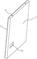
FIG. 1 is a schematic structural diagram of a prefabricated wall panel special for a building integrated photovoltaic plant according to an embodiment of the present application.
Fig. 2 is an enlarged view of a portion a in fig. 1.
Fig. 3 is a schematic structural diagram for embodying the aligning rod in the embodiment of the present application.
Fig. 4 is a schematic structural diagram for embodying a photovoltaic panel in an embodiment of the present application.
Description of reference numerals: 1. a wallboard; 101. a dovetail groove; 2. a photovoltaic panel; 21. a positioning groove; 22. mounting grooves; 3. a clamping assembly; 31. a first clamping plate; 32. a second clamping plate; 33. accommodating grooves; 34. a dovetail block; 35. an alignment rod; 36. a first spring; 4. a limiting component; 41. mounting a plate; 42. a slide bar; 43. pulling the block; 44. a suction cup; 45. a second spring; 5. a cushioning pad.
Detailed Description
The present application is described in further detail below with reference to figures 1-4. The embodiment of the application provides a special prefabricated wallboard of building integrated photovoltaic formula factory building, it has the effect of conveniently loading and unloading.
Referring to fig. 1, the special prefabricated wallboard of integrated factory building of photovoltaic building includes wallboard 1, photovoltaic board 2 and clamping components 3. Photovoltaic board 2 sets up in one side of wallboard 1, and photovoltaic board 2 is about 1 parallel arrangement of wallboard. The clamping assembly 3 comprises a first clamping plate 31 and a second clamping plate 32 which are arranged in parallel on the same side of the wall panel 1, the first clamping plate 31 is slidably connected to the wall panel 1, the second clamping plate 32 is fixedly connected to the wall panel 1, and the first clamping plate 31 can move in a direction close to or away from the second clamping plate 32. The photovoltaic panel 2 is disposed between the first clamping plate 31 and the second clamping plate 32, the accommodating groove 33 is formed in the first clamping plate 31 and the second clamping plate 32 along the length direction of the first clamping plate, and the accommodating groove 33 is disposed on one side of the first clamping plate 31 and the second clamping plate 32, which are close to each other. When the photovoltaic panel 2 is mounted between the first clamping plate 31 and the second clamping plate 32, opposite ends of the photovoltaic panel 2 are located in the receiving grooves 33.
Referring to fig. 1, when a plurality of photovoltaic panels 2 are installed, the photovoltaic panels 2 are placed between a first clamping plate 31 and a second clamping plate 32, and the position of the first clamping plate 31 is adjusted to clamp the photovoltaic panels 2, so that the photovoltaic panels 2 are installed. When the photovoltaic panel 2 is damaged, the photovoltaic panel 2 is taken out from between the first clamping plate 31 and the second clamping plate 32 and is repaired and replaced.
Referring to fig. 1 and 2, two dovetail grooves 101 are formed in parallel on the wall panel 1, and a length direction of the dovetail grooves 101 is perpendicular to a length direction of the first clamping plate 31. One side of the first clamping plate 31 close to the wall plate 1 is fixedly connected with two dovetail blocks 34, the two dovetail blocks 34 are arranged in one-to-one correspondence with the two dovetail grooves 101, and the dovetail blocks 34 are embedded in the dovetail grooves 101 in a sliding manner. The dovetail groove 101 is provided with a first spring 36 along the length direction thereof, one end of the first spring 36 is fixedly connected with the dovetail block 34, and the other end is connected with the inner wall of the dovetail groove 101 far away from the second clamping plate 32. The first clamping plate 31 is further provided with a limiting component 4 for connecting with the wall plate 1.
Referring to fig. 3 and 4, the accommodating groove 33 of the first clamping plate 31 is provided with a plurality of alignment rods 35, the alignment rods 35 are provided along the length direction of the first stiffening plate, and one end of the photovoltaic panel 2 is provided with alignment grooves 21 corresponding to the alignment rods 35 in number and position.
Referring to fig. 1 and 2, the limiting assembly 4 is provided with a plurality of groups along the length direction of the first clamping plate 31, and the limiting assembly 4 comprises a mounting plate 41, a sliding rod 42, a pulling block 43 and a suction cup 44. Sucking disc 44 with draw block 43 respectively fixed connection and the both ends of slide bar 42 length direction, mounting panel 41 fixed connection is on first clamp plate 31, slide bar 42 run through mounting panel 41 and rather than sliding fit, slide bar 42 set up the direction perpendicular with wallboard 1, sucking disc 44 sets up in the one end that slide bar 42 is close to wallboard 1. The slide rod 42 is sleeved with a second spring 45, one end of the second spring 45 abuts against the mounting plate 41, and the other end abuts against the suction cup 44.
Referring to fig. 1, 3 and 4, when the photovoltaic panel 2 is installed, one end of the photovoltaic panel 2, at which the alignment groove 21 is opened, is placed in the accommodating groove 33 of the first clamping plate 31, and the alignment rod 35 is inserted into the corresponding alignment groove 21. The first clamping plate 31 is pushed away from the second clamping plate 32, the dovetail block 34 slides in the dovetail groove 101, and the first spring 36 is shortened to accumulate elastic potential energy. One end of the photovoltaic panel 2, which is far away from the first clamping plate 31, is placed in the accommodating groove 33 of the second clamping plate 32, the photovoltaic panel 2 is loosened, the first spring 36 extends to release elastic potential energy, and the first clamping plate 31 and the photovoltaic panel 2 are abutted. The structural stability between the clamping component 3 and the photovoltaic panel 2 is increased by the arrangement of the first spring 36, the limit of the photovoltaic panel 2 is realized by the arrangement of the alignment rod 35 and the alignment groove 21, and the possibility that the photovoltaic panel 2 slides between the first clamping plate 31 and the second clamping plate 32 is reduced.
Referring to fig. 1 and 2, after the photovoltaic panel 2 is installed, the pulling block 43 is pulled away from the wall panel 1, the second spring 45 is compressed to shorten the accumulated elastic potential energy, the pulling block 43 is released, the second spring 45 releases the elastic potential energy to extend, the suction cup 44 is contacted with the wall panel 1 and is adsorbed on the wall panel 1 under the action of the second spring 45, the connection between the first clamping plate 31 and the wall panel 1 is realized, and the structural stability of the device is further improved.
Referring to fig. 1 and 4, photovoltaic board 2 has a shock pad 5 towards one side fixedly connected with of wallboard 1, and mounting groove 22 has been seted up to one side that photovoltaic board 2 deviates from wallboard 1. When installing photovoltaic board 2 in one side of wallboard 1 the shock pad 5 with the outer wall butt of wallboard 1, reduced the impaired possibility of photovoltaic board 2. The installation groove 22 is provided to facilitate the insertion of the operator's hand into the photovoltaic panel 2 during installation.
In the embodiment of the application, an implementation principle of the special prefabricated wallboard of photovoltaic building integrated factory building is as follows: when the photovoltaic panel 2 is installed, one end of the photovoltaic panel 2, at which the alignment groove 21 is opened, is placed in the accommodating groove 33 of the first clamping plate 31, and the alignment rod 35 is inserted into the corresponding alignment groove 21. The first clamping plate 31 is pushed away from the second clamping plate 32, the dovetail block 34 slides in the dovetail groove 101, and the first spring 36 is shortened to accumulate elastic potential energy. One end of the photovoltaic panel 2, which is far away from the first clamping plate 31, is placed in the accommodating groove 33 of the second clamping plate 32, the photovoltaic panel 2 is loosened, the first spring 36 extends to release elastic potential energy, and the first clamping plate 31 and the photovoltaic panel 2 are abutted.
After the photovoltaic panel 2 is installed, the pulling block 43 is pulled in the direction away from the wallboard 1, the second spring 45 is pressed to shorten the accumulated elastic potential energy, the pulling block 43 is loosened, the second spring 45 releases the elastic potential energy to extend, the suction cup 44 is contacted with and adsorbed on the wallboard 1 under the action of the second spring 45, the connection between the first clamping plate 31 and the wallboard 1 is realized, and the structural stability of the device is further improved.
The above embodiments are preferred embodiments of the present application, and the protection scope of the present application is not limited by the above embodiments, so: all equivalent changes made according to the structure, shape and principle of the present application shall be covered by the protection scope of the present application.
Claims (8)
1. The utility model provides a special prefabricated wallboard of photovoltaic building integrated formula factory building which characterized in that: including wallboard (1) and set up in photovoltaic board (2) of wallboard (1) one side, one side of wallboard (1) is provided with clamping component (3), clamping component includes first clamp plate (31) and second clamp plate (32), all offer on first clamp plate (31) and second clamp plate (32) and be used for holding tank (33) of photovoltaic board (2), holding tank (33) set up in first clamp plate (31) and one side that second clamp plate (32) are close to each other, first clamp plate (31) can be along being close to or keeping away from the direction of second clamp plate (32) slides, photovoltaic board (2) set up in first clamp plate (31) with between second clamp plate (32).
2. The special prefabricated wall panel for the integrated photovoltaic building factory building of claim 1, wherein the prefabricated wall panel comprises: the improved wall plate is characterized in that a dovetail groove (101) is formed in the wall plate (1), the dovetail groove (101) is formed in the edge of the connecting line direction of the first clamping plate (31) and the second clamping plate (32), the first clamping plate (31) is close to one side of the wall plate (1) and is connected with a dovetail block (34), and the dovetail block (34) is embedded in the dovetail groove (101) in a sliding mode.
3. The special prefabricated wall panel for the integrated photovoltaic building factory building of claim 2, wherein: a first spring (36) is arranged in the dovetail groove (101) along the length direction of the dovetail groove, one end of the first spring (36) is connected with the dovetail block (34), and the other end of the first spring (36) is connected with the inner wall, far away from the second clamping plate (32), of the dovetail groove (101).
4. The special prefabricated wall panel for the integrated photovoltaic building factory building of claim 1, wherein: photovoltaic board (2) are by the warp one side of wallboard (1) is provided with bradyseism pad (5), works as photovoltaic board (2) install in first clamp plate (31) with when second clamp plate (32) between, bradyseism pad (5) with wallboard (1) butt.
5. The special prefabricated wall panel for the integrated photovoltaic building factory building of claim 3, wherein: be provided with counterpoint pole (35) in holding tank (33) on first pinch-off blades (31), counterpoint pole (35) are along the length direction of first pinch-off blades (31) is provided with a plurality of, seted up on the edge of photovoltaic board (2) a plurality of with counterpoint groove (21) that counterpoint pole (35) correspond, a plurality of counterpoint groove (21) and a plurality of counterpoint pole (35) one-to-one sets up.
6. The special prefabricated wall panel for the integrated photovoltaic building factory building of claim 4, wherein the prefabricated wall panel comprises: mounting groove (22) have been seted up on photovoltaic board (2), mounting groove (22) set up in photovoltaic board (2) deviate from one side of bradyseism pad (5).
7. The special prefabricated wall panel for the integrated photovoltaic building factory building of claim 6, wherein: be provided with spacing subassembly (4) on first pinch-off blades (31), spacing subassembly (4) include mounting panel (41), slide bar (42), draw piece (43) and sucking disc (44), mounting panel (41) connect in on first pinch-off blades (31), slide bar (42) run through mounting panel (41) and rather than sliding fit, slide bar (42) are close to the one end of wallboard (1) with sucking disc (44) are connected, the other end of slide bar (42) with draw piece (43) to connect.
8. The special prefabricated wall panel for the integrated photovoltaic building factory building of claim 7, wherein: the cover is equipped with second spring (45) on slide bar (42), the one end of second spring (45) with sucking disc (44) butt, the other end with mounting panel (41) butt.
Priority Applications (1)
| Application Number | Priority Date | Filing Date | Title |
|---|---|---|---|
| CN202221913865.3U CN217734572U (en) | 2022-07-22 | 2022-07-22 | Special prefabricated wallboard of photovoltaic building integrated factory building |
Applications Claiming Priority (1)
| Application Number | Priority Date | Filing Date | Title |
|---|---|---|---|
| CN202221913865.3U CN217734572U (en) | 2022-07-22 | 2022-07-22 | Special prefabricated wallboard of photovoltaic building integrated factory building |
Publications (1)
| Publication Number | Publication Date |
|---|---|
| CN217734572U true CN217734572U (en) | 2022-11-04 |
Family
ID=83849794
Family Applications (1)
| Application Number | Title | Priority Date | Filing Date |
|---|---|---|---|
| CN202221913865.3U Active CN217734572U (en) | 2022-07-22 | 2022-07-22 | Special prefabricated wallboard of photovoltaic building integrated factory building |
Country Status (1)
| Country | Link |
|---|---|
| CN (1) | CN217734572U (en) |
-
2022
- 2022-07-22 CN CN202221913865.3U patent/CN217734572U/en active Active
Similar Documents
| Publication | Publication Date | Title |
|---|---|---|
| CN209941986U (en) | Curtain wall construction convenient to installation | |
| CN203942481U (en) | A kind of roof hook structure | |
| CN111477585A (en) | Full-size battery piece group automatic adsorption transfer device and working method thereof | |
| CN217734572U (en) | Special prefabricated wallboard of photovoltaic building integrated factory building | |
| CN209429420U (en) | A kind of color steel roofing photovoltaic power generation plate pedestal quick installation mechanism | |
| CN111438089A (en) | Automatic cleaning device for solar photovoltaic panel | |
| CN114826099A (en) | Polymer photovoltaic board and installation fixed knot construct thereof | |
| CN220291925U (en) | Building energy-saving roof | |
| CN112038276A (en) | Mechanism based on silicon chip inserted sheet cleaning machine inserted sheet stability reinforcing | |
| CN204349862U (en) | Fixture and there is its photovoltaic module erecting device | |
| CN220421690U (en) | Mounting rack for photovoltaic module | |
| CN220417131U (en) | Novel LED lamp | |
| CN210640844U (en) | Solar photovoltaic cell module | |
| CN218255260U (en) | Power distribution management device for cooperative robot | |
| CN217789630U (en) | Photovoltaic board convenient to clearance with additional strengthening | |
| CN211084260U (en) | Outer machine mounting structure of building air conditioner | |
| CN218633774U (en) | Photovoltaic module clip | |
| CN213825704U (en) | Automatic gluing machine for solar panel frame | |
| CN215674285U (en) | Low-smoke heat insulation plate | |
| CN219118584U (en) | Photovoltaic module backboard, photovoltaic roof piece and layer structure | |
| CN220254394U (en) | Photovoltaic solar power generation equipment convenient to dismantle | |
| CN220775728U (en) | Plug-in type photovoltaic photo-thermal assembly | |
| CN219316139U (en) | Quick detach formula photovoltaic curtain | |
| CN220707764U (en) | Trough type solar concentrator supporting sheet | |
| CN212063891U (en) | Solar assembly for construction site zero-carbon attendance sentry box |
Legal Events
| Date | Code | Title | Description |
|---|---|---|---|
| GR01 | Patent grant | ||
| GR01 | Patent grant |